Milled housings
A recessed body with a lid face, mounting holes and internal features. Identify the cavity envelope, connector openings and the surfaces that locate or seal the assembly.
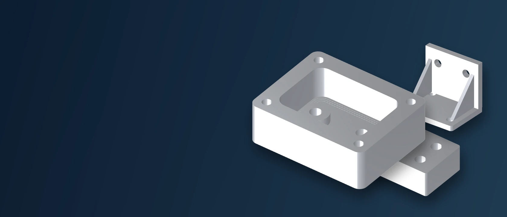
A recessed body with a lid face, mounting holes and internal features. Identify the cavity envelope, connector openings and the surfaces that locate or seal the assembly.
Brackets for sensors, instruments and mechanical assemblies. Define the mounting faces, locating holes and the relationship between upright and base features.
Machined bases with drilled, bored or threaded hole patterns. Separate clearance holes from locating holes and identify the datum faces used to inspect them.
Blocks with connected passages, ports and mounting features. Provide the port callouts, passage connections, sealing details and any required cleaning or test procedure.
Milled bases for thermal or electrical assemblies. Mark the contact area, fastening pattern and finished surface requirements; material and performance targets must be specified separately.
Inserts with sculpted faces, pockets or blending surfaces. Provide the complete 3D model and identify which surfaces control fit, appearance or the working profile.
Components with holes and features on several sides. Show how those features relate to shared datum faces, including any angular or position requirements.
Machined polymer parts that support, guide or separate other components. Specify the exact material and the conditions under which fit, clearance and dimensions will be checked.
No matching examples. Add a part line for your own drawing or reset the filters.
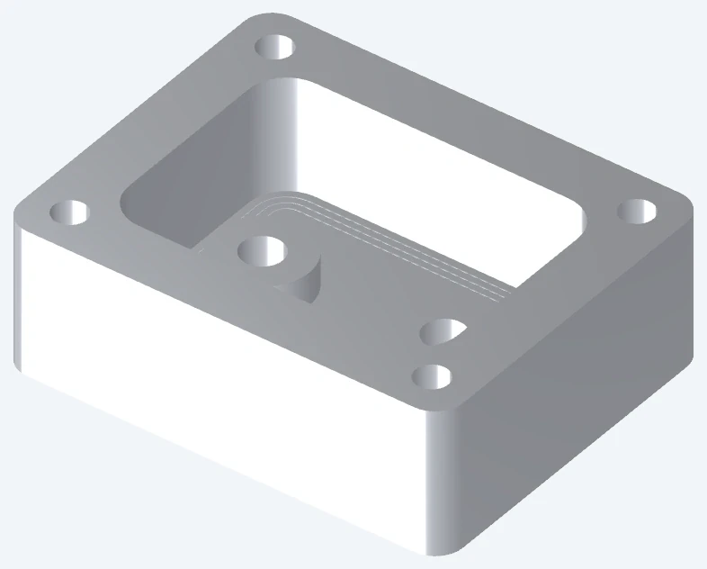
Specify the exact alloy and supply condition, not just “metal.” Include any final hardness, heat treatment or corrosion-related requirements in the drawing review.
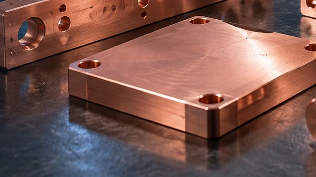
Use the specified grade and condition for contact parts, ported blocks or other specialized components. Describe the working environment and identify any material records needed.
Identify the surfaces that seat against another component. Add the required flatness, orientation, roughness and final finish to the released drawing. A cosmetic face and an assembly datum may need different treatment.
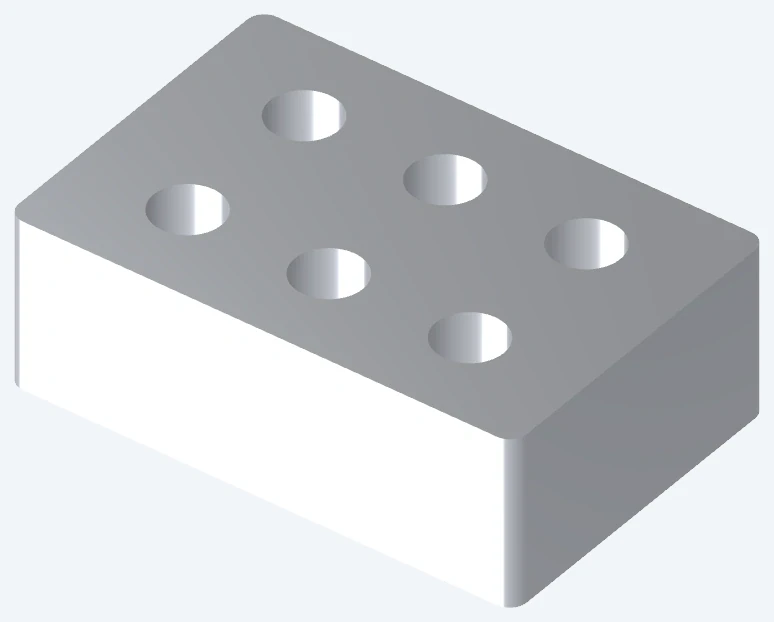
Separate locating bores from clearance and tapped holes. Reference the intended datums, show complete thread callouts and distinguish a hole-size tolerance from its location requirement.
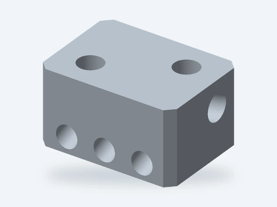
For a part machined from several directions, identify the shared references that connect its features. Include position, parallelism, perpendicularity or profile controls only where the design requires them.
| Feature | Include on the drawing | What to review before production |
|---|---|---|
| Internal corners | Required radius, mating geometry and any permitted relief. | A rotating milling cutter leaves a radius at an internal corner. Where a square mating feature must fit, discuss an approved relief or another process rather than changing the drawing silently. [1] |
| Deep or narrow pockets | Pocket depth, opening width, floor thickness and any inaccessible features. | Depth and access affect the tool and setup. Review the whole cavity rather than assuming every surface can be reached from the same direction. [2] |
| Thin walls and ribs | Finished wall thickness, critical faces and permitted distortion. | Thin features can deflect during cutting or clamping. Review support, machining sequence and the condition in which the part will be inspected. [3] |
| Tapped and precision holes | Hole type, diameter, depth, full thread designation and usable thread length. | Distinguish a drilled pilot depth from the usable thread depth. Call out a locating fit separately from a clearance hole. [4] |
| Undercuts and hidden surfaces | Section views, access direction and the permitted cutter relief. | Flag features that cannot be reached by a standard tool approach. An additional setup, different tool or alternative process requires review, not an automatic promise. [4] |
| Freeform surfaces | Current 3D model, working profile and surface requirements. | Mark which areas matter to fit or function, and agree how the resulting surface will be checked. Appearance alone is not a substitute for a defined profile requirement. [2] |
Send the finished geometry, not an assumed machining setup. A plate may be straightforward from one side, while side holes, underside pockets or a second datum face can change the workholding plan.
Where features must relate across faces, the process review considers access, clamping and the drawing’s datum scheme. Extra orientations are not evidence that a part automatically needs simultaneous five-axis machining.
Indexed or simultaneous multi-axis machining may be considered for angled or sculpted features. The appropriate route depends on the actual geometry and agreed inspection requirements. [4]
Define roughness on functional areas and distinguish tool marks from unacceptable damage. Show deburring and edge-break requirements without leaving a critical sharp edge open to interpretation.
Mark coated areas, masking and any coating specification. Confirm whether the stated dimensions apply before or after finishing, particularly on locating bores, threaded holes and mating faces.
Identify the supply and final material conditions, required hardness and any post-treatment machining or inspection. Review the order of operations before approving the first batch.
Identify cosmetic faces, clear viewing areas, polishing boundaries and protective packing. Do not apply metal finishing assumptions to a polymer part; use the specified material and approved process.
Finishing options are reviewed for the specified material and order. Agree the final drawing condition before accepting the quote. [5]
Request the checks that support the actual assembly: hole locations, fitted bores, datum-face relationships and surface requirements. Agree the inspection scope, sampling and reporting format before production, rather than assuming every dimension will receive the same record.
State whether acceptance follows machining, heat treatment, coating or a defined conditioning step. Include any installation or temperature condition that matters to the fit. A measurement taken in one state should not be presented as proof of another.
Specify the part number, revision, material records and batch identification you need. The first sample review should also cover protective packing for sealing faces, threads and visible surfaces.
Match the part number, material, revision and required quantities. Resolve unclear features before treating a quote as a production specification.
Define what will be checked and which records are needed. Any change to a corner radius, finish or material needs your approval.
Confirm the sample decision, final drawing and production quantity. Identify whether an approved change applies to one item or the complete parts list.
Reference the approved revision and finish. Flag changes to quantities, delivery schedules or acceptance requirements instead of relying on an old purchase order alone.
Ask for the quotation to distinguish material, setup, machining, finishing and inspection where useful. Deep features, difficult access and tightly controlled surfaces deserve an early drawing review. Send sample and production quantities separately so the comparison uses the same specification.
| Include | Details to provide |
|---|---|
| 3D model plus 2D drawing | Use the model for geometry and the drawing for critical dimensions, datums, material and finish requirements. State which file controls if a discrepancy is found. |
| Complete milling features | Include pocket depths, corner radii, minimum wall sections, full hole and thread callouts, and any critical relationships between faces. Mark units explicitly. |
| Matching part numbers | For a multi-part inquiry, match every model and drawing to one line in the list. A descriptive file name is useful, but it does not replace a revision on the drawing. |
| Requirements beyond geometry | Include quantity options, sample approval, inspection records, packaging, delivery destination and any relevant assembly notes. Agree the transfer method before sending confidential or restricted files. |
Choose a milled part above or add a line for your own drawing. Expand each line to add pocket, hole and datum requirements.
This list organizes your inquiry. It does not calculate prices, confirm availability or approve a manufacturing specification. Entries stay in this page unless you download them or submit them to a configured quote endpoint.
I’m Kevin. I have spent ten years in the CNC industry, following a business my father’s generation built through exhibitions and long-standing customers. We have several factories in China, and I want new customers to understand the work before they commit to an order.
Send us the drawings and explain what the components need to do in your assembly. Where our own factories are not the right match, I would rather explain that and discuss a suitable partner than make a promise the project cannot support.
Read the vetcnc storyWe can discuss production through our factories, coordination with a partner, or a direct introduction so you can work with that company yourself. Agree the manufacturing, inspection and communication responsibilities before ordering.
Discuss Your PartsThey are examples of part geometry, not catalog items with fixed dimensions or stock. Your drawing, material, quantity and acceptance requirements define the order. Adding an example to the inquiry list does not select a ready-made product.
This page helps you identify component types and organize a parts inquiry. The milling service page explains the process in more detail. You can request housing, bracket, plate and other component quotes here without opening individual product pages.
Send the complete model and drawing, including the relationship between the faces. The review will determine the required access and setup and whether indexed or simultaneous multi-axis machining is appropriate. Capability is confirmed for the actual component.
Send the required tolerances on the drawing, especially locating bores, hole patterns and mating faces. Feasibility depends on the complete geometry, material, process and inspection condition. We do not publish one blanket tolerance as a guarantee for every part.
Conventional milling leaves a radius where the rotating cutter forms an internal corner. Identify the mating requirement, then discuss a permitted corner relief or alternative process. A design change must be agreed rather than assumed.
Provide the exact grade and condition when known, along with any required material record. Where selection is still open, describe the environment, load and mating components so alternatives can be discussed. A gallery image does not identify or approve a material.
State the process, applicable specification, finish areas and any masking. Identify dimensions that must be accepted after finishing and show the required cosmetic or functional surfaces. Availability and process suitability are reviewed for each material and order.
Include the sample and production quantities in your inquiry, along with the checks needed before release. The order, price and schedule are agreed after drawing review. A sample request does not establish a universal minimum order or lead time.
Yes. Add each component as a separate line, with its own material, revision and quantity. Expand the line for pocket, hole, datum and finish requirements. Name the matching CAD and drawing files so the list can be checked without guessing.
List material records, dimensional inspection, sample approval, revision identification and packing needs before quotation. Agree which records will be supplied and which faces need individual protection. Do not infer a certification or test scope from the example images.
This is a drawing-based inquiry page, not a manufacturing specification. The references below support general process terminology. Materials, tolerances, finishing, testing and manufacturing responsibilities must be agreed for the actual order. No third-party capacity, precision or certification is represented as a vetcnc capability.