
Skip to guide
vetcncCNC MANUFACTURING
Illustrative machined housing, bracket and fixture block for a material and design discussion

CNC Machining
Materials & Design

Choose the material around what the part has to do

A material name is only the beginning of a CNC part specification. Start with what the part has to do: carry a load, slide against another component, hold a position, conduct heat or keep a surface visible. Then identify the conditions it will face and the dimensions that must still work after machining and finishing.

Keep fixed requirements separate from questions that are open to discussion. A mandatory material specification should stay fixed; a possible alternative should be identified as a proposal for your approval. The same distinction applies to a corner radius, wall thickness or coating.

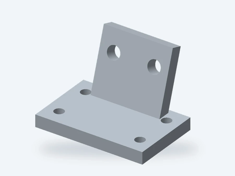
Illustrative mounting bracket

For a mounting bracket, discuss the mounting faces, loads and fastener positions before deciding which material or feature can change.

Which requirements matter to your part?

Select one or more topics. They will be added to your review brief as questions, not used to approve or automatically select a material.

The guide is a discussion aid. Your drawing, material specification and approved design remain the controlling documents.

Compare CNC materials without treating them as interchangeable

Material families and the information to confirm before CNC machining
Material familyWhat to establish before choosing a gradeExplore the material
Aluminum alloysRecord the alloy, temper and stock form. Identify cosmetic surfaces and any finish that must leave functional areas uncoated.Aluminum CNC machining →
Steel & stainless steelSeparate the material grade from the required heat-treatment or hardness condition. Identify corrosion exposure and the dimensions to check after processing.Steel CNC machining →Stainless steel →
Copper & brassState the electrical, thermal or mechanical requirement rather than asking only for a copper-colored part. Specify the contact surfaces, plating and material restrictions.Copper CNC machining →Brass →
Titanium & nickel alloysName the exact alloy and supply condition. Confirm the specification and required records before proposing a change of stock or processing route.Titanium CNC machining →Inconel →
POM & nylonCompare the actual grades, loads, sliding contact and measurement conditions. Nylon moisture absorption can change dimensions and mechanical behavior.[4]POM CNC machining →Nylon →
PEEK & acrylicDo not group plastics only by appearance. Specify the PEEK formulation or PMMA stock type, the required function, exposure and any visible surfaces.PEEK CNC machining →Acrylic →

Compare exact grades, not just families

Use the same operating conditions, stock condition and acceptance requirements when comparing candidates. A family name does not establish the properties of a particular alloy, polymer formulation or finished component.

Do not choose by machining time alone

Different materials introduce different cutting and surface-quality considerations.[2] A useful quote comparison also includes raw stock, processing, finishing, inspection and the cost of testing an alternative that has not yet been approved.

Put the grade, condition and stock form on the drawing

Grade and specification

State the alloy or polymer designation and the applicable material specification. Include the required revision where relevant. Similar names should not be taken as permission to substitute.

Condition and formulation

Record the temper, hardness or heat-treatment condition for metals. For plastics, name any reinforcement, filler, wear additive or manufacturer-specific grade.

Stock form and direction

Identify plate, bar, tube or another required form. Where your design depends on stock direction, identify the orientation on the drawing rather than leaving it to layout decisions.

Records and substitutions

List the certificates and lot records to retain. State whether alternatives may be proposed, who can approve them and how the approval must be documented.

A more useful material note“6061-T6 aluminum; applicable specification and stock form as stated on the drawing; alternatives require written approval.” Complete the specification before release. This is an example of the information to capture, not an approved drawing note.

Include temperature, moisture and load in the fit requirements

Moisture belongs in the nylon fit discussion

Polyamide absorbs moisture, and the resulting change can affect both dimensions and mechanical properties.[4] State whether a dimension is checked in an agreed as-machined state, after conditioning or in service. Include the mating component and operating environment.

A low-moisture material still needs a defined grade

POM has low moisture absorption and is used for sliding components; homopolymer and copolymer versions are distinct materials.[5] Record the exact grade rather than assuming all acetal stock is equivalent. Review temperature, load duration and contact conditions for the selected grade.

Ask for the data relevant to the actual use

For a warm, loaded or chemically exposed part, request the supplier data needed to evaluate that combination. A room-temperature property, a color or a sample that fits once does not by itself answer every service question. Keep material suitability and dimensional inspection as separate checks.

When changing from metal to plastic: reopen the wall design, fastener interfaces, fit and inspection conditions. Treat the change as a design review, not a direct purchase-order substitution.

Review corners, pockets, walls and threads before release

A pocket with a rounded internal corner and a circular cutterCutterInside radiusTop view · schematic only

Internal corners need room for a rotating cutter

A cylindrical cutter leaves a radius at an internal pocket corner. A smaller corner can require a smaller tool; engagement also changes as the cutter enters the corner.[1]

Mark the largest radius your assembly can accept. Any proposed relief or change to the mating part needs design approval.

Tool reach into a pocket with clearance around the holderDepthCheck holder clearanceSection view · cutting length and holder access are separate checks

Deep pockets need access for the holder as well as the tool

Depth alone does not describe tool access. Review the opening, nearby walls and the reach needed to get to the bottom. The tool and holder both need clearance.

Identify which depth and floor features are functional. Ask whether the opening or nonfunctional geometry can change before approving a revised shape.

A thin wall during clamping and after release shown schematicallyWhile clampedAfter releaseCheck freeconditionDeflection is exaggerated. The drawing defines acceptance.

Thin walls must be reviewed in their unclamped state

A wall that is supported during cutting may behave differently after release. Wall height, material and surrounding geometry matter alongside thickness.

Mark the faces that may be clamped and define the final measurement condition. Do not copy a minimum wall value from another part without reviewing this geometry.

A blind threaded hole with separate full thread and drill depthsUsablethread depthDrill depthSection view · leave clearance beyond the usable thread

Keep usable thread depth separate from drill depth

A blind hole needs a clear definition of the usable thread and the space beyond it. The drill point and thread-making method affect how that bottom region is handled.

Give the thread standard, size, pitch, class and usable length. Include insert requirements and the required final condition after finishing.

Schematic teaching examples, not to scale. They do not specify minimum wall thickness, hole depth limits, a toolpath or a validated machining method. [3]

Define fits after finishing, not only after machining

Schematic mating shaft and bore, with an optional exaggerated added surface layerMating boreMating shaftGap
Check the final assembly condition

This sketch separates the shaft, bore and clearance. Select the second view to see an exaggerated added layer; it is not a coating calculation.

Mark the dimensions that apply after finishing

A deposited layer can add to an outside surface and reduce an opening. The net dimensional effect depends on the process and its specification; do not assume every treatment behaves like this sketch.[6] Mark final fit limits, masked areas and any surfaces to finish afterward.

Identify the datums that locate the assembly

Give the supplier the actual reference faces, bores or axes from the drawing. When a hole pattern must align with another part, describe that relationship rather than tightening every unrelated dimension.

Separate size, geometry and surface texture

State which features require a size check, a geometric check or a surface-texture check. Include the applicable drawing conventions and the final condition to measure. A requested inspection method should be agreed alongside the acceptance criteria.

The blue layer is exaggerated for explanation. It does not represent anodizing growth, plating thickness, a press fit or an approved assembly.

Three part examples show why material and geometry need one review

A housing with a mating cover

Identify the cover interface, locating faces, holes and any sealing requirement. Mark the visible zones separately from the surfaces that control fit.

Question to resolve
Could a nonfunctional pocket corner be enlarged without affecting the cover or internal components?
Before release
Record any approved radius change, final finish and interface inspection on the released drawing.

A polymer bushing around a metal shaft

Name the actual polymer grade, mating shaft, housing retention and movement. Record moisture, temperature and load conditions relevant to the fit.

Question to resolve
Does the inspection condition match how the bushing will be installed and used?
Before release
Agree conditioning, assembly checks and who approves the material before comparing trial parts.

A copper plate with a contact surface

Distinguish the electrical or thermal interface from mounting and cosmetic surfaces. Provide the contact requirements and any specified plating.

Question to resolve
Which surfaces may be coated, and which dimensions must remain within limits after processing?
Before release
Confirm masking, final surface condition, dimensional records and protection during packing.

These are review scenarios, not customer case studies. Suggested changes require approval from the person responsible for the design.

Release one consistent set of material and drawing requirements

01

Match the 3D model and 2D drawing

Use the same part number and revision. State which document controls when a note or dimension conflicts, and resolve the conflict before manufacture.

02

Separate mandatory requirements from proposals

Identify what must remain unchanged and what can be discussed. List approved alternatives explicitly rather than using an open-ended “or equivalent.”

03

Call out interfaces and inspection conditions

Identify functional datums, fits, thread requirements, finish and any conditioning or assembly state used for acceptance.

04

Agree the release and change process

Record the approved revision and the person who can authorize changes. Keep changes to material, geometry and outsourced processing traceable to that decision.

A trial part needs a defined purpose

State whether the sample is for assembly, dimensional review, appearance or a functional test. A change in material or finish between the sample and production should trigger a review of what that sample actually demonstrated.

Review proposals before comparing prices

Keep any proposed alternative separate from a quote for the released definition. Otherwise, a lower price may reflect a different material, inspection scope or geometry rather than a like-for-like offer.

Questions about CNC material selection and part design

Which material is best for a CNC-machined part?

There is no useful single answer without the application. Start with function, environment, interfaces and any mandatory specifications. Compare exact candidates against those requirements, then review how the part will be manufactured and checked.

Can I ask vetcnc to propose an alternative material?

Yes. Identify the current grade and which requirement you want to improve or clarify. A proposed alternative should be listed separately and approved by the person responsible for the design before it is used.

Should a metal and a plastic part use the same drawing?

Not automatically. Revisit wall geometry, fastening, fit, service conditions and acceptance when changing the material. Release a clear revision for the approved definition instead of leaving an informal substitution in an email.

How small can an internal corner radius or wall be?

The answer depends on the geometry, material, access, support and required result. Share the drawing and identify what cannot change. This guide deliberately does not publish a universal radius or minimum wall as a capability promise.

Do all dimensions need the tightest tolerance?

State tolerances according to function. Identify mating dimensions and geometric relationships, and use clearly defined general requirements where appropriate. Ask how critical features will be checked instead of applying one demanding tolerance to every surface.

Should my drawing show dimensions before or after coating?

Make the required condition explicit. Mark final functional limits, any masking and any machining after treatment. The processor and manufacturer should agree how the specified finish and dimensional requirements will be achieved.

What should I send for a material and design review?

Send matching model and drawing revisions, the material specification, quantities, service conditions, critical interfaces, finishing requirements and open questions. Highlight requirements that cannot change and proposals that need your approval.

Does the online review brief approve my material or design?

No. It records your inputs and selected discussion topics. It does not calculate strength, select a grade, validate an assembly or confirm manufacturing capability. Those decisions need the actual specification and an agreed technical review.

Prepare your material and design review brief

Information to include in the discussion

The brief stays in this browser until you choose to download it or submit through a configured quote form. It is not an approved design or manufacturing instruction.

Technical reading and scope of this guide

General process explanations were checked against the following manufacturer resources. Their capabilities and numerical limits are not vetcnc capability claims. Diagrams and review scenarios are explanatory; confirm the actual grade data, drawing requirements and manufacturing plan for your part.

  1. Sandvik Coromant — Milling inside corners
  2. Sandvik Coromant — Milling different materials
  3. Protolabs — CNC milling design considerations
  4. Ensinger — PA / polyamide: moisture and material behavior
  5. Ensinger — POM / acetal: material families and properties
  6. Protolabs — CNC machining finishing options
vetcncCNC MANUFACTURING

Get a Quote

Design preview. This form is not connected; no files or details will be sent.

Upload Drawing

*Required fields

Share only files you are authorized to disclose. Agree confidentiality and the transfer channel before sending sensitive information.

Illustration

Email us