01 / OPERATION
OD Turning & Facing
Straight and stepped diameters, end faces, tapers and profiles. Identify the functional surfaces and any transitions that must match a mating part.
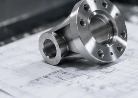
For a useful manufacturing discussion, show how the part fits and works. A bearing seat, sealing surface or threaded connection can each require a different acceptance check—even when they sit on the same component.
Review drawing requirements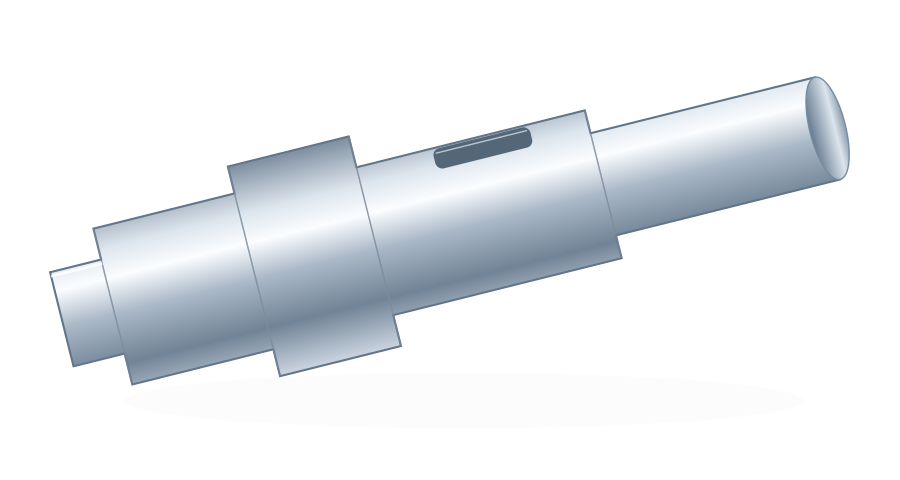
Tell us what the part needs. We will confirm the tooling, workholding and secondary operations before accepting the job.
Straight and stepped diameters, end faces, tapers and profiles. Identify the functional surfaces and any transitions that must match a mating part.
Provide bore diameter, depth and whether the hole is blind or through. Tool reach and chip clearance matter for deeper internal features.[2]
Specify the thread form, pitch, fit class and useful length. For grooves, show the width, depth, radii and the function they perform.
Flats, keyways and cross-holes may need live tooling or a separate milling operation. The route depends on equipment, access and the drawing.[3]
Long slender parts, deep bores, small features or special alloys need a part-specific review. Swiss-type turning and grinding are not assumed to be part of every job.
Multiple diameters and shoulders for drive, locating or support functions.
Discuss: Bearing seats · shoulder spacing · datum axis
Hollow cylindrical parts with a defined relationship between the bore and outside surface.
Discuss: Bore fit · wall thickness · surface condition
Round interfaces with faces, bores and optional mounting features. Hole patterns may add a milling step.
Discuss: Face location · bore alignment · bolt pattern
Custom threaded connectors and adapters made to a defined mating specification.
Discuss: Thread form · fit class · usable thread length
Locating and joining parts with controlled diameters, lengths and end details.
Discuss: Diameter fit · straightness · end geometry
Round spacing and locating components designed around the dimensions of your assembly.
Discuss: Face spacing · bore clearance · edge treatment
| Material | What to specify | Request a quote |
|---|---|---|
| Aluminum Alloys | Alloy and temper, finish requirements and the final dimensions of mating surfaces. | |
| Stainless Steel | Grade, supplied condition, required surface finish and any passivation specification. | |
| Steel | Grade, hardness, heat-treatment sequence and any post-treatment machining requirements. | |
| Titanium Alloys | Grade, material traceability and critical surfaces or handling requirements. | |
| Brass | Alloy, any lead-content restrictions and the thread or sealing details. | |
| Copper | Grade, application requirements, finish and any appearance-sensitive surfaces. | |
| Inconel Alloys | Exact alloy, supplied condition and the full acceptance specification for review. | |
| PEEK | Exact grade, reinforcement or fillers and application-specific documentation. | |
| POM / Acetal | Grade, color, fillers if any and the working dimensions of sliding or mating features. | |
| Nylon | Grade, reinforcement and the condition in which dimensions must be inspected. | |
| Acrylic / PMMA | Grade, appearance requirements and whether optical finishing is part of the scope. |
Need a different grade? Include the exact specification and required documentation. Substitutions require your approval.
| Requirement | Information to include |
|---|---|
| Diameters & fits | Nominal diameter, tolerance or fit designation, mating requirement and drawing units. Identify every bearing, sliding or press-fit surface. |
| Datums & runout | Identify the reference surfaces or axis and the required geometric controls. Keep diameter size, roundness and runout as distinct requirements. |
| Lengths & faces | Overall length, shoulder locations and any flatness, face-runout or perpendicularity callouts required by your design. |
| Internal features | Bore size, depth, entry details and any internal shoulders or grooves. State whether holes are blind or through. |
| Threads | Full designation, pitch, tolerance class, handedness, useful length and the required gauge or acceptance method. |
| Surface & final condition | Roughness parameter and units, edge treatment, heat treatment, coating specification and whether dimensions apply before or after finishing. |
Discuss supported length, workholding and whether center features are allowed. Slender sections can be sensitive to cutting forces and vibration; their acceptance criteria should be clear.[4]
Show the working bore length and internal geometry. Increasing tool overhang can make vibration, deflection and chip evacuation harder to control.[2]
Define the important free-state dimensions and allowable clamping surfaces. Review how the part will be held, machined and inspected without changing the functional design.[4]
Show usable thread length, mating engagement and any relief or runout permitted at the end. Do not rely only on a rendered CAD thread to convey the specification.
Show groove width, depth, corner details and the sealing or retaining specification. Ask for a review of the required tool access and inspection method.
Mark angular relationships to other features. These details can need an additional setup or live tooling; confirm the route instead of assuming every feature is turned.[3]
Design changes are proposals for your review—not automatic edits to the part. Keep drawing revisions and approvals aligned before production.
Inquiry preference: Not specified
A finishing process is not a substitute for a surface specification. Identify the areas that need a particular roughness or final dimension.[4]
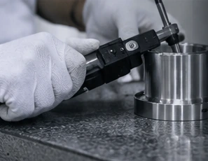
Identify critical dimensions, datums and any material or finishing records. Agree the inspection scope and reporting format as part of the order.
Diameter, thread fit, runout and surface roughness call for different checks. Confirm suitable measuring equipment and acceptance methods for the specified features.
For repeat batches, confirm the approved drawing revision, sample requirements, inspection frequency and the way parts or lots need to be identified.
When a partner process is needed, agree who performs the work, who checks it and who handles questions about conformity before the order is placed.
Start with the design questions the sample needs to answer: fit, assembly, surface condition or functional testing.
State the sample quantity and the acceptance decision it supports.Confirm the released revision, quantity, finishing, inspection and packaging before producing the first batch.
Discuss any first-piece approval and its effect on the schedule.Share expected order frequency and any changes to quantities or requirements between batches.
Agree revision control and repeat-order scope rather than assuming they remain unchanged.Start with a drawing that separates essential features from preferences. Include the initial quantity and likely repeat quantities so the manufacturing plan can be discussed in context.
Exact grade, supplied condition, sourcing requirements and material removed from the starting shape.
Part geometry, workholding, tool access and secondary operations such as cross-drilling, milling or grinding.
Coatings, masking, required records and inspection scope—not just time on the lathe.
Setup shared across a batch, repeat-order scope, material availability and the requested delivery destination.
Minimum order quantity, production lead time and shipping arrangements are confirmed per project. No instant price or unverified delivery promise is shown here.
“My father built this business through trade shows and long-standing customers. I want to carry that experience forward—and make it easier for you to understand who is making your parts.”
Our manufacturing roots are in China, with multiple factories and a wider circle of manufacturing partners. The aim is straightforward: explain what fits our capabilities and be open about the route when a project needs something different.
Discuss a direct manufacturing scope when the part fits.
Agree the partner work, communication and responsibilities in advance.
Where appropriate, connect with a suitable partner and discuss the work directly.
Bushings, sleeves and interface components. Confirm traceability and qualification requirements.
Application RequirementsInstrument and assembly components. Specify material, cleanliness and documentation needs.
Application RequirementsShafts, pins, spacers and adapters. Identify critical fits and repeat-batch requirements.
Application RequirementsShare qualification and information-handling requirements before exchanging restricted drawings.
Application RequirementsPrecision interfaces and equipment components. Discuss surface and cleanliness requirements.
Application RequirementsApplication examples do not establish sector approval or certification. Specialized requirements are reviewed before a project is accepted.
Send the CAD model, matching drawing, material, quantity and target delivery.
Discuss fit, tooling, stock, finishes, inspection and any partner processing.
Confirm price, revision, acceptance requirements and delivery arrangements in writing.
Proceed to the agreed production, inspection, records and packaging plan.
Turning rotates the workpiece and is commonly used for round profiles, faces and diameters. Milling uses rotating cutters to create features such as pockets, flats and hole patterns. A part can require both processes.[1][3]
Yes—start with your own part specification. The examples on this page illustrate part families, not stocked items. Send your model and matching drawing so we can review the shape, material, quantity and acceptance requirements.
These need a drawing-based review. Provide the outside diameter, total length, material, critical fits and geometric controls. The quote confirms accepted requirements; a generic machine envelope or tolerance is not used as a promise for every part.
Include those features in the inquiry with their full dimensions and acceptance requirements. Thread forms, useful length, bore depth, groove access and the workholding arrangement all need review before the scope is confirmed.
These features may be produced with live tooling or an additional milling setup. Mark their locations and angular relationships on the drawing. The quotation should identify the proposed process route, not assume all features are completed in one setup.[3]
Do not assume either is included in a standard turning inquiry. Send the slenderness, dimensions and surface requirements that drive the need. We can discuss whether a specialist route, partner coordination or direct introduction is appropriate.
Include the quantity you actually need and what the first parts must demonstrate. Minimum quantities, setup costs and any sample-approval stages are agreed for the project rather than advertised as one rule for every component.
The drawing, material condition, quantity, tooling, secondary operations, finish, inspection and delivery requirements define the scope. Share a requested delivery date; the achievable schedule and any dependencies are confirmed in the quote.
Our first step is to review the fit with our factories. For work outside that fit, we can discuss coordinating suitable partners or making an introduction. Agree the manufacturing parties, inspection responsibilities and commercial relationship before placing the order.
A STEP or IGES model plus a matching PDF drawing is a useful starting point. Include units, part number and revision. This preview accepts one file or a ZIP up to 20 MB, but sends nothing. Agree confidentiality and an appropriate transfer method before sharing sensitive or restricted information.
Not ready to share confidential files? Start with a non-sensitive project description and state any confidentiality requirements.
General process guidance is based on the references below. Their published machine limits, tolerances, prices and delivery claims are not vetcnc specifications. Acceptance is always confirmed for the actual part.