Skip to guide
vetcncCNC MANUFACTURING
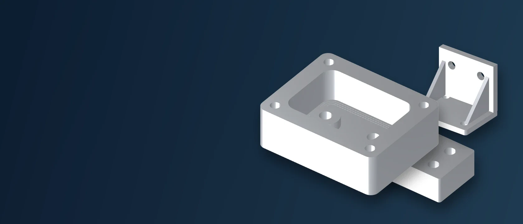
Illustrative milled housing, bracket and fixture block; not a customer project

CNC Machining
Basics

What is CNC machining?

CNC stands for computer numerical control. In CNC machining, a programmed machine guides cutting tools to remove material and produce a part from a block, bar or other workpiece.[1]

This is a subtractive process: the starting material is cut away. It differs from 3D printing, which builds a shape by adding material. A housing may start as a solid block; a shaft may start as round bar.[2]

The program controls movement, but the drawing, cutting tools, workholding and inspection plan still need to suit the part. For a buyer, the starting point is the required component—not a machine model or a promised number of decimal places.[3]

Explore CNC machining services

Milling, turning and 5-axis machining explained

The cutting tool rotates

Milling shapes pockets, faces and holes

A rotating cutter moves relative to a held workpiece. Milling is used for features such as flat faces, slots, pockets and hole patterns. A part may need more than one setup to reach its other sides.[4]

CNC milling services
The workpiece rotates

Turning produces round features

The workpiece rotates while a cutting tool feeds along or across it. Shafts, sleeves, bushings and round shoulders are common examples. Flats or off-center holes may need live tooling or another operation.[5]

CNC turning services
Extra axes change access

Multi-axis machining reaches more faces

Three-axis machining uses linear X, Y and Z movements. In 3+2 machining, rotary axes position the part before cutting. Simultaneous five-axis machining can change the tool-to-part angle during a cut.[6]

5-axis machining services
The number of axes is not a quality grade. Ask which setup reaches the required features and how those features will be checked. A part can combine milled and turned features.

From a CAD model to a checked part

Review the CAD model and drawing

Confirm the part number, revision, material and quantities. Resolve conflicting dimensions or notes before treating the design as released.

Plan the tools and toolpaths

CAD describes the geometry. CAM helps plan tool movements; post-processing converts that plan into code for the intended machine and controller.[7]

Prepare stock and workholding

Choose a suitable blank, hold it securely and establish the workpiece location. Tool access and clamping need to be planned together.

Rough and finish the features

Roughing removes most of the unwanted material. Finishing passes bring surfaces toward the specified size and surface condition. More setups may be needed.[4]

Complete the specified secondary work

Deburring, coatings, heat treatment or other work belong in the agreed route when required. Identify which dimensions apply after the final process.

Inspect, identify and pack the parts

Check the agreed characteristics against the correct revision. Keep each delivery linked to its part identity, quantity and required records.

What should you check on a CNC part drawing?

The 3D model defines the shape

Share a suitable CAD file, such as STEP, when available. A model without manufacturing annotations may leave tolerances, finish and inspection requirements undefined.

The drawing adds manufacturing requirements

Use the 2D drawing or agreed model-based definition to communicate critical features, units, material and notes. Do not assume a plain model contains every requirement.

Simplified drawing of a mounting plateA plate with four holes, an internal pocket, an overall size, a hole callout and a revision box. These are examples of drawing information, not a released technical drawing.80.0040.004 × Ø6 THRUInternal radiusIllustration only · dimensions in mmPART: EXAMPLE-01REV: AUNITS: mm1234
This schematic is not a production drawing and does not define a complete part specification.

Check the units and revision

A millimeter drawing and an inch drawing cannot be treated as interchangeable. Use the same revision in the model, drawing and purchase order.

Read dimensions with their tolerances

An overall dimension tells you the size. Its permitted variation may be stated next to it or in an applicable general note.

Read the complete hole or thread callout

Diameter, depth and through/blind condition are different requirements. A threaded hole also needs its thread specification and required depth.

Read feature and finish notes

Check internal radii, edge requirements and surface notes. Look for any datum references and geometric controls elsewhere on the drawing, using its specified standard.[8]

Two files disagree? Ask which is authoritative and request a corrected revision. Do not silently choose the more convenient dimension.

Size, tolerance and surface finish are different requirements

20.00 ± 0.05 mm
19.9019.95 lower limit20.05 upper limit20.10
20.00 mmWithin this example’s size limits

Teaching example only. It checks the arithmetic range, not a real part’s acceptance. Other drawing requirements, measurement uncertainty and the agreed decision rule are not evaluated.

A dimension gives the intended size

In the example, 20.00 mm is the nominal value. Applying ±0.05 mm gives a lower size limit of 19.95 mm and an upper limit of 20.05 mm. The total interval is 0.10 mm, not 0.05 mm.

A size limit does not define every geometric requirement

Position, orientation and form can require separate controls. A hole’s diameter can be within its size limits while its location is unsuitable for the assembly. Read the full drawing, including its geometric tolerances.[8]

Surface finish describes another part of the specification

A polished appearance is not proof of dimensional accuracy. Ask for the relevant surface texture requirement and the complete treatment specification, then identify which features must be checked after finishing.

Specify the material and the finished condition

What to identifyWhat to include in the RFQ
Metal or engineering plasticName the material family, then the specific grade and condition. “Aluminum” or “plastic” alone may not identify what you need.
Material conditionInclude the required temper, hardness or other specified condition. Separate the state of the purchased stock from the condition required at delivery.
Mating parts and working conditionsDescribe the assembly, load, temperature, chemicals and contact surfaces that matter. The responsible design team should approve any material substitution.
Required treatmentIdentify the surfaces to be coated, masked, polished or left as machined. Include the finish specification rather than relying on a reference color alone.

Ask how the finished part will be checked

Match the method to the feature

Workpiece inspection compares a part’s measured geometry or dimensions with its design requirements. Checks can occur during machining as well as after it. Ask which features will be measured, by which method and in what condition.[9]

Request the records you actually need

For your RFQ, separate material certificates, dimensional results and finishing records. List the records that must accompany the parts and identify the drawing revision they should reference.

Agree the next step after the sample

Clarify whether a sample is for a fit check, a dimensional review or customer approval before a production release. Record unresolved items rather than treating a good-looking sample as approval of every requirement.

Give suppliers the same information when comparing quotes

Use the same released design

Send the same files, revision, material and finished condition to each supplier. A price based on an older model is not directly comparable with a quote for the current one.

Separate quantities and order stages

List prototype, trial-batch and released production quantities separately. Ask what is included for setup, tooling, finishing, inspection and packing rather than comparing only the displayed unit price.

Define delivery and acceptance

State when parts are needed and what has to happen before production or dispatch. Ask whether quoted timing includes external processing and inspection, and identify any approvals still outstanding.

A forecast is not a released order. Label anticipated repeat demand separately from the quantity you are asking the supplier to make now.

CNC terms you will see in drawings and quotes

CAD
Computer-aided design. The digital model or drawing used to describe a part.
CAM
Computer-aided manufacturing. Software used to prepare machining toolpaths and related manufacturing instructions.
G-code
A form of machine-control instruction. The intended machine and controller need an appropriate program.
Stock / blank
The starting material before the required features are machined.
Setup
An arrangement of workholding, tools and workpiece references for a group of operations.
Datum
An ideal reference used to locate or orient features. The drawing identifies the real datum features used to establish it.
Tolerance
The permitted variation specified for a dimension or other controlled characteristic.
GD&T
Geometric dimensioning and tolerancing: symbols and rules for communicating geometric requirements.
Surface roughness
A description of small-scale surface texture, using the stated parameter, units and measurement conditions.
Deburring
Removing unwanted sharp projections left by processing. Edge-break limits still need to follow the specification.
Material condition
The specified state of a material, such as an alloy temper, heat-treated condition or polymer grade.
DFM review
Design-for-manufacturing review: a discussion of whether the proposed features and requirements suit the manufacturing route.
RFQ
Request for quotation: the files, quantities and requirements submitted to obtain a price and delivery proposal.
Drawing revision
The identifier of a particular design issue. It helps distinguish the approved definition from older files.
First article
An initial part or representative build examined against an agreed verification plan. Required records depend on the order.

Plain-language definitions for orientation. Drawing terminology follows the standard specified on the drawing; see the technical references.[7][8][9]
Questions before your first CNC machining order

Is CNC machining the same as 3D printing?

No. Machining removes material from a starting workpiece; 3D printing adds material to build a shape. Both can be used during product development, but their design constraints and resulting parts are not interchangeable.[2]

Do I have to choose the exact CNC machine?

You can start with the part definition and what it needs to do. Share any mandatory process restrictions, then ask the supplier to propose the route. The number of machine axes alone does not specify an achievable tolerance.

Do I need a 2D drawing as well as a 3D model?

Provide a drawing when the model does not contain the complete manufacturing requirements. A properly agreed model-based definition can carry additional information, but a plain shape file should not be assumed to do so. Keep all supplied files at the same revision.

Does every dimension need a very tight tolerance?

Start with the functional requirements set by the designer. Identify critical interfaces, apply the stated general tolerances where appropriate and agree the inspection scope. This guide does not prescribe a default tolerance for your part.

Can the same part need both milling and turning?

Yes. A round part can also have flats, slots or off-center features. These can require live-tool operations or a separate machining setup, depending on the equipment and geometry.[4][5]

What should I send for an initial quote?

Share the part number, current model and drawing, material and finished condition, quantity, critical requirements, requested records and delivery needs. A preliminary inquiry is still useful when something is unresolved—mark the open questions clearly.

What happens when a drawing is incomplete?

Identify the missing information before releasing production. A supplier can ask questions or propose alternatives, but the authorized design or purchasing contact should confirm changes to material, dimensions, finish and acceptance requirements.

Prepare the information for your first CNC quote

Which information have you prepared?

0 of 6 information groups marked prepared. This is not a production approval.

Entries stay in this browser until you submit through a configured form. Downloading the checklist does not send it to vetcnc.

Technical references and teaching notes
  1. Autodesk — What is CNC machining?
  2. Autodesk — Additive and subtractive manufacturing
  3. Sandvik Coromant — Machining considerations and workholding
  4. Sandvik Coromant — Milling applications and considerations
  5. Sandvik Coromant — Turning fundamentals
  6. Haas Automation — 3+2 and simultaneous five-axis machining
  7. Autodesk — Introduction to CAD, CAM and practical CNC milling
  8. ASME — Y14.5 dimensioning and tolerancing
  9. Renishaw — Workpiece setup and inspection

This guide provides an introduction, not a manufacturing specification or a substitute for the standard invoked by a drawing. The dimension example and drawing illustration are original teaching examples. Supplier-specific capability, inspection and acceptance must be agreed for the actual order. Technical references checked on 19 September 2026.

vetcncCNC MANUFACTURING

Get a Quote

Design preview. This form is not connected; no files or details will be sent.

Upload Drawing

*Required fields

Share only files you are authorized to disclose. Agree confidentiality and the transfer channel before sending sensitive information.

Illustration

Email us