Skip to guide
vetcncCNC MANUFACTURING
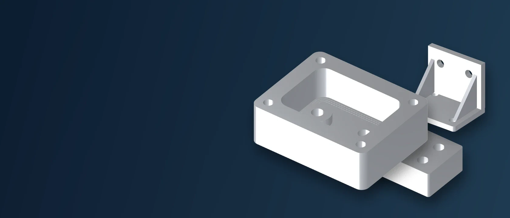
Illustrative milled housing, mounting bracket and fixture block

CNC Machining
Processes

Start with the features on your CNC part drawing

Choose the process around the features your part needs—not the machine name on a supplier’s website.

CNC machining is a family of computer-controlled manufacturing methods. A single part may need milling, turning, hole finishing and threading, rather than one operation from start to finish.[9]

Begin with the drawing: identify the surfaces that locate the part, the features that mate with other components and the condition required at delivery. A useful process discussion then asks how those requirements will be produced and checked.

What features are on your drawing?

Select a feature to see which operations to discuss and what information to prepare.

View the process comparison →

This guide explains options; it does not select or approve a manufacturing route.

Compare CNC machining processes by the features they produce

CNC process comparison by feature and drawing review
ProcessWhat it is used forWhat to check on the drawing
MillingFlat faces, pockets, slots and profiles[1]Tool access, internal corners, wall thickness and datums
TurningDiameters, shoulders and rotational profiles[2]Support, overall length, mating diameters and runout
DrillingA new hole or a hole prepared for later work[3]Diameter, depth, entry/exit geometry and hole location
BoringEnlarging or finishing an existing hole[4]Bore size, position, straightness and surface requirements
ReamingFinishing a prepared hole to specified limits[5]Prepared-hole quality, allowance and workholding
Tapping / thread millingInternal threads; thread milling can also cut external threads[6]Thread standard, pitch, class and full thread depth
3+2 / simultaneous 5-axisMulti-face access and features requiring tool orientation changes[7]Orientation, fixture clearance and the surfaces to be reached
Operations are not machine categories. A machining center can carry out several of these operations. Hole and thread requirements should be specified by their final geometry, not only by a process name.

CNC milling vs. turning: look at the shape first

CNC milling for faces, pockets and profiles

A milling cutter rotates while the tool and workpiece move relative to one another. The same setup may include face milling, pocketing and drilling, with a different cutter or toolpath for each feature.[1]

For a housing or bracket, mark the mounting face, hole pattern and any mating edges. A supplier can then discuss access to each surface rather than treating every visible face as equally critical.

If an internal corner must clear a mating part, show the allowed radius or relief on the drawing. That requirement is more useful than simply asking for a “sharp corner.”[8]

Explore the machining service →

CNC turning for diameters, shoulders and bores

In conventional turning, the workpiece rotates while a non-rotating cutting tool feeds along the part. Typical features include stepped diameters, end faces and rotational profiles.[2]

For a shaft or sleeve, identify the bearing seats, shoulder locations and bore requirements. Note which features must be evaluated relative to a common datum axis.

A round part can also need flats or cross-holes. Ask whether those features will be produced with live tooling on a suitable lathe or in a separate milling setup; the drawing must remain the same in either route.

Explore the machining service →

Drilling, boring and reaming do different jobs

Drilling starts the hole

Drilling produces the initial hole. Its diameter, depth and entry or exit conditions influence the tool and method; some holes are then finished by a later operation.[3]

Specify a blind or through hole, any step or countersink and the hole’s required position.

Boring works on an existing hole

Boring removes material from an existing opening. It can be used to enlarge a bore or finish its size and geometry using tooling selected for the requirement.[4]

Call out the bore limits, depth, finish and relationship to the part’s datums.

Reaming finishes a prepared hole

Reaming uses a multi-edge tool to remove a controlled allowance from a prepared hole. The result depends on hole preparation, alignment and a stable setup.[5]

Define the final hole requirement. Do not assume a reamed hole automatically meets its location requirement.

Conceptual cross-sections only. Tool proportions, allowances and setup are not production instructions.

Specify the finished thread before choosing tapping or thread milling

Tapping uses a dedicated thread tool

Cutting taps remove material; forming taps displace it. Selection depends on material, hole type and the specified thread. A tap suitable for one application is not automatically suitable for another.[6]

Thread milling follows a helical path

A rotating cutter follows a circular path while advancing axially to produce the thread. It is a different operation from tapping and needs an appropriate machine, program and tool.[10]

External threads may also be produced by thread turning. The purchase requirement should identify the finished thread and its inspection—not leave the thread form to be inferred from a nominal diameter.

Put the complete thread requirement on the drawing

Thread definition
Standard, nominal size, pitch, tolerance class and handedness where relevant.
Usable length
Full thread depth or length, plus the hole condition at the end.
Finished condition
Any coating, plating or insert requirements at delivery.
Acceptance
The required gauge or inspection basis, and any mating-part check.

A partial note such as “threaded hole” is not a complete manufacturing specification.

When are 3-axis, 3+2 or simultaneous 5-axis machining useful?

3-axis machining

The tool moves along three linear axes. Faces or features that cannot be reached in one orientation may need another setup; some accessible 3D profiles can still be machined with three axes.

3+2 positional machining

Two rotary axes position the workpiece or tool, then remain fixed during a three-axis cutting move. The purpose is to reach features at a useful orientation.

Simultaneous 5-axis machining

Linear and rotary axes can move together during a cutting path. This supports changing tool orientation as the surface is machined. It is not a blanket promise of tighter tolerances.

Axis terminology and access considerations.[7] [11]

Ask what changes for your part. Which surfaces need repositioning? Can the fixture support them without blocking the tool? What is the inspection plan? Compare those answers before choosing a route only because it has more axes.

One part can need several machining operations

Housing with a pocket

Confirm whether the sealing face is accepted before or after the specified finish.

  1. Establish the reference surfaces

    Discuss the mounting face and locating edges before planning the other features.

  2. Machine the pocket and hole pattern

    Group accessible features and leave any required finishing work in the plan.

  3. Access the remaining faces

    Review a second setup or indexed orientation for side and underside features.

  4. Finish and inspect the released features

    Keep finishing, thread checks and inspection tied to the same drawing revision.

Shaft with a cross-hole

Confirm which diameters establish the datum axis for runout checks.

  1. Locate and support the blank

    Discuss the datum axis and how the part will be supported during the proposed route.

  2. Turn the main diameters and shoulders

    Identify the mating diameters and the shoulder positions that require inspection.

  3. Add non-rotational features

    Review a live-tool or secondary milling operation for the cross-hole or flats.

  4. Complete the final condition and checks

    Agree the sequence for any heat treatment, grinding or coating before final acceptance.

Block with angled features

Ask how angled feature locations will be related back to the released datums.

  1. Agree the datum structure

    Identify the reference faces and the features whose positions must relate to them.

  2. Create the accessible reference features

    Discuss how the stock and fixture will expose the features needed for later operations.

  3. Reorient for the angled features

    Compare a fixture change, 3+2 positioning or simultaneous work where the surface requires it.

  4. Check geometry after secondary work

    Plan inspection for the final drawing condition, including any specified coating or surface work.

These are discussion examples, not approved process plans, fixed setup counts or evidence of completed customer work. The manufacturing route must be reviewed for the actual drawing, material and equipment.

Plan roughing, finishing and secondary work together

Roughing and finishing serve different purposes

Roughing removes stock efficiently; finishing brings selected features toward their required size, form and surface condition. The stages may need different tools and cutting strategies.[11]

The material condition belongs in the plan

Ask whether the quote starts from the required material condition and includes the finished condition. A raw-material grade alone is not a complete instruction for a heat-treated or coated component.

Inspection has to match the final requirement

On-machine probing can support setup and process checks, but the inspection plan should still state how the ordered characteristics are verified and recorded.[12]

Existing AI machining scene. Not evidence of installed vetcnc equipment.

Agree who owns each step of the route

For secondary work, confirm the responsible site or partner, the sequence, any approvals and the records included with delivery. Ask who checks the part after that operation—not only who performs it.

At vetcnc, the discussion can cover work in our factories, coordinated partner work or a direct introduction where that arrangement better fits the project. Any arrangement should identify the scope, responsibility and acceptance requirements before an order is released.

How we work with customers →

Review access, datums and acceptance before comparing quotes

Tool access and internal corners

Deep pockets, small internal corners and surrounding walls affect access. Mark the surfaces that actually need a close fit and identify any permitted corner relief before requesting a smaller tool.[8]

Datums and workholding

Ask how the part will be located as it moves between operations. Specify which faces may show clamping marks and which surfaces must remain protected.

Quantity and repeat orders

Give suppliers separate prototype and production quantities. Ask whether dedicated fixtures, setup work and repeat-order assumptions are included rather than comparing only the unit price.

Inspection after the last specified operation

A dimensional result before plating or another surface process may not answer a requirement for the finished part. State the delivery condition and the required records together.

Questions about choosing a CNC machining process

Do I need to specify a machining process before asking for a quote?

Not always. Send a clear model and drawing, then identify any mandatory process restrictions or qualified route. Otherwise, ask the supplier to explain the proposed route and how it meets the requirements. Do not treat the route as approved until the responsible parties have reviewed it.

Can the same part need milling and turning?

Yes. Round diameters and shoulders may be turned, while flats or off-axis features need additional operations. A suitable machine may combine operations; another route may use a separate setup. Ask how the drawing datums will be maintained.

Is 5-axis machining always the best choice?

No. The relevant question is whether changing tool orientation improves access or the process for this geometry. Include setup, fixturing, programming and inspection in the comparison rather than using axis count as a quality rating.

Are boring and reaming the same as drilling?

No. Drilling makes an initial hole; boring works on an existing opening; reaming finishes a prepared hole. The required size, geometry, location and surface condition determine what must be evaluated. A process label alone does not define acceptance.

Can a machined internal corner be perfectly sharp?

A rotating milling cutter leaves a radius where its geometry meets the corner. Show the allowed radius or relief. A feature that cannot be reached or produced by the proposed milling route may require a design review or another process; do not assume it can be machined as drawn.

Can the machining route change after sample approval?

Define this in the order requirements. Ask which changes need notification or reapproval, including changes to the site, fixture, material condition or secondary processor. A sample approval should identify what was accepted and under which revision.

What should I send for a process review?

Provide the part model, drawing revision, material and condition, quantities and final finish. Highlight fits, datums, threads, inspection records and any required or prohibited operations. Mark undecided items instead of allowing them to become silent assumptions.

Does this guide confirm which processes vetcnc can supply for my part?

No. It explains common process terminology and the information useful for a discussion. The actual manufacturing site, process scope, material, limits, inspection and delivery commitments need to be confirmed against your project.
Prepare your CNC process review brief

Information to include in the discussion
Topics added from this guide

No topics added yet.

Your entries stay in this page until you choose to send them. The preview does not submit data.

Technical references and example notes
  1. Sandvik Coromant — Milling operations and considerations
  2. Sandvik Coromant — General turning
  3. Sandvik Coromant — Drilling a hole
  4. Sandvik Coromant — Boring holes
  5. Sandvik Coromant — Reaming
  6. Sandvik Coromant — Tapping
  7. Haas Automation — 5-Axis Machining Simplified
  8. Sandvik Coromant — Milling inside corners
  9. Autodesk — What is CNC machining?
  10. Sandvik Coromant — Thread milling
  11. Sandvik Coromant — Profile milling
  12. Renishaw — Workpiece setup and inspection

Technical terminology was checked against the manufacturer references above on 19 September 2026. The selection prompts, diagrams and example routes are editorial teaching aids, not production plans. No source is presented as an endorsement of vetcnc or evidence of its equipment, qualifications or process capability.

vetcncCNC MANUFACTURING

Get a Quote

Design preview. This form is not connected; no files or details will be sent.

Upload Drawing

*Required fields

Share only files you are authorized to disclose. Agree confidentiality and the transfer channel before sending sensitive information.

Illustration

Email us