
Drive and coupling shafts
We turn the shaft contacts and machine the selected keyways, flats or bolt connections. The drive end and the connection to the screw or rotor remain related through those operations.
Discuss This Component
We machine drive shafts, feeder end plates, replaceable wear details and service hardware for biomass-handling equipment. Our components connect the feed mechanism, retained housing and drive through their specified contacts, from a first fit check to repeat spares.
Fuel-handling equipment combines torque transmission, material contact and maintenance access. We supply the individual drawing-defined parts rather than complete boilers, pressure feeders or combustion systems.
We turn the shaft contacts and machine the selected keyways, flats or bolt connections. The drive end and the connection to the screw or rotor remain related through those operations.
Discuss This Component
An end plate relates the shaft opening to the retained feeder body. Its seating face, central reference and fixing pattern determine where the rotating assembly sits.
Discuss This Component
A replaceable contact keeps the wearing surface on a defined component. We machine its support face and fastening features while preserving the working profile and material condition selected for that contact.
Discuss This Component
Turned hubs and spacers locate the selected drive or support parts axially. Their bore, shoulder and end faces establish the contact stack rather than leaving assembly position to an overall outside length.
Discuss This Component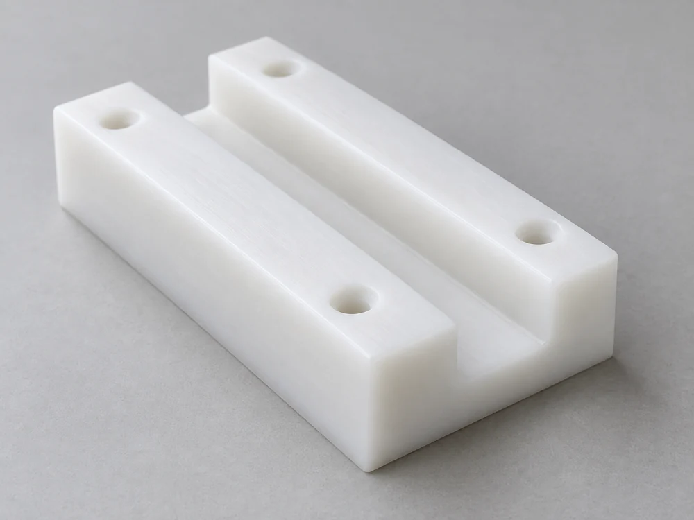
Machined guides and mounting details hold a moving or replaceable part at its selected reference. The retained contact and access for changing the detail are both part of that geometry.
Discuss This Component
A removable plate needs its fitted perimeter and fastening positions as well as a clear removal path. We keep access features separate from the surfaces that locate the working mechanism.
Discuss This ComponentThe useful machining answer depends on how the mechanism moves and where the material contacts it. A coupling shaft, a feeder end plate and a wear insert serve different assembly functions.
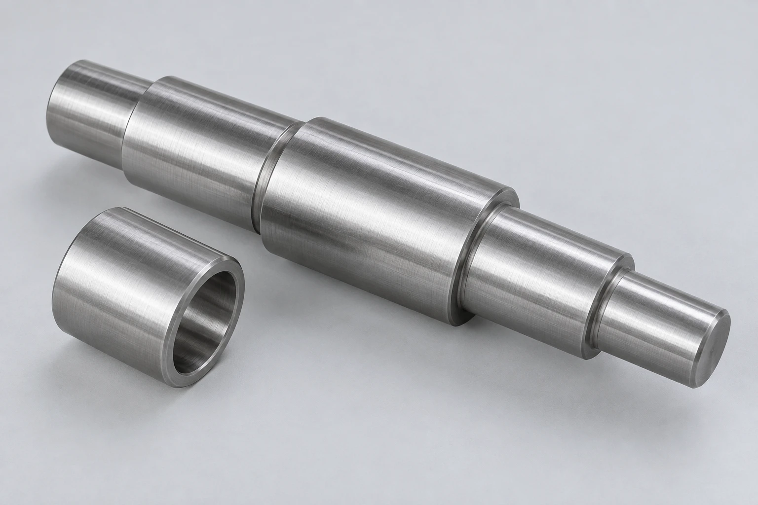
A screw connection joins the drive shaft, coupling hardware and screw section. We machine the released shaft form and attachment so the retained components have their defined relationship.
KWS distinguishes shaft, coupling-bolt and screw-pipe construction in its component guidance. A replacement definition needs the actual connection arrangement, not a shaft diameter selected in isolation.
The shaft contact and coupling features share the chosen drawing references.
Shoulders and reliefs leave the installed drive, support and fasteners their required room.
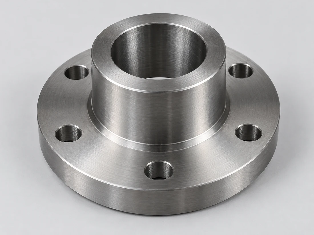
The rotor position is related to the end plates and retained housing. A new carrier or end plate must preserve the selected shaft location and contact stack without assuming that every clearance around the rotor has the same purpose.[1]
ANDRITZ’s rotary-valve guidance separates vane tips, end plates, packing and outboard bearing arrangements. We supply the specified machined detail; the complete valve and its operating acceptance remain the equipment builder’s scope.
Central references and contact faces establish the intended installed position.
Fastening and access follow the selected packing, bearing or cover arrangement.
A replaceable block or strip needs a stable support face beneath the wearing profile. Its fasteners and removal path should remain reachable after adjacent feed and guard hardware is installed.
We keep the drawing-defined contact separate from the non-working exterior. A local worn detail can then be replaced without treating every surrounding housing surface as a new machined datum.
The mounting region supports the selected wear profile and fixing load.
The released geometry leaves the intended clearance for removal and fastening.
A new part can establish where the mechanism fits. A working build also needs the selected material state, surface condition and complete rotating or wear-contact arrangement.
A trial part establishes insertion, fastening and removal around the retained equipment. Any simplified material or finish remains identified so its assembly result has a clear boundary.
The selected stock, treated areas and final contacts are supplied together for the intended equipment evaluation. The measured component revision identifies the actual hardware in that build.
A stable revision shares programming and setup across a run. Treated stock, interrupted profiles, several machining faces and additional surface checks still add work to each part; quantity does not remove those operations.
A drive shaft and a wearing strip need different material properties. The selected grade, stock form and treatment remain attached to the particular contact; dry tooling is identified separately from hot or fuel-contacting hardware.[3]
| Material reference | Parameter values | Stock / test basis |
|---|---|---|
| Hardox 450 wear plate | 425–475 HBW | SSAB plate; 3.2–80.0 mm thick |
| 42CrMo4 +QT · Ovako 327A | Rm 900–1,100 MPa; 270–320 HB | Round bar; 40 < diameter < 100 mm |
| 316L / EN 1.4404 | Elastic modulus 200 GPa | Outokumpu Supra; 20°C |
| POM-C · TECAFORM AH natural | Tensile modulus 2,800 MPa | DIN EN ISO 527-2 at 1 mm/min (dry tooling) |
Stock references: SSAB Hardox 450 plate, 3.2–80.0 mm hardness range. Ovako 327A, 42CrMo4 +QT round bar, 40 < diameter < 100 mm. Outokumpu Supra 316L/4404 at 20 °C. Ensinger TECAFORM AH natural, DIN EN ISO 527-2 at 1 mm/min. Throughput and service life require separate equipment evaluation.
The manufacturing route connects the load-bearing contact, driving feature and installed reference. Stock hardness, interrupted cuts and tool approach influence that route alongside the outside size.
Milling establishes mounting lands, openings and local reliefs. The support beneath a working profile remains available during cutting and in the finished part rather than disappearing into an unnecessary deep pocket.
CNC Milling ServicesTurning relates the shaft contacts, bores and axial stops. Secondary keyways or coupling holes retain those references when the component moves into another setup.
CNC Turning ServicesSide openings and recessed fixings need a reachable machining direction. The route accounts for tool clearance around retained ribs, shoulders and hardened or coated regions.
5-Axis Machining OptionsThe local contact controls how the component works. The wear profile, the retained shaft position and the service opening are each defined on the local contact surfaces that make the component work.

Coupling holes or keyways connect the shaft to the selected screw or hub. Their location, engagement and retained section are defined with the mating parts, rather than from a convenient hole in the blank.[4]
Radial tip clearance, axial position and the end-plate interface describe different regions. The selected feeder drawing identifies which surfaces establish those relationships.
The working profile receives the specified material condition while its back face seats on the retained support. A thin unsupported edge does not become a useful wear surface simply by choosing a harder alloy.
A carrier or cover leaves space for the selected packing and its installed hardware. Removal access remains distinct from the dimensional references used to locate the working assembly.
The wearing contact, fitted shaft seat and general exterior do different jobs. We retain their selected material and surface condition through the delivered component.
Prehardened stock and a separately treated region require different routes. The quotation identifies the actual material state and which features receive final machining after any included treatment.
Deburring clears projections from entries and fixing holes while preserving the intended bearing land or wearing profile. A broad exterior blend is not applied across a narrow functional contact.
An ordered exterior coating keeps its specified coverage while fitted seats or moving contacts retain their defined condition. The coating boundary is part of the delivered geometry rather than a reason to rework the fit during installation.
The following KWS shafted-conveyor references connect the selected shaft diameter with its pipe and coupling-bolt arrangement. They identify a construction choice; they do not assign capacity to a custom biomass component.
We check the finished connection, contact profile and mounting references against the released drawing. The accepted stock and treatment condition accompany those measurements; whole-assembly load, feeding and safety acceptance are defined separately.
| Shaft / feature reference | Matching construction | Acceptance basis |
|---|---|---|
| 1 in shaft | 1-1/4 in nominal pipe; 3/8 in bolt | KWS standard two-bolt construction |
| 1-1/2 in shaft | 2 in nominal pipe; 1/2 in bolt | KWS standard two-bolt construction |
| 2 in shaft | 2-1/2 in nominal pipe; 5/8 in bolt | KWS standard two-bolt construction |
| 2-7/16 in shaft | 3 in nominal pipe; 5/8 in bolt | KWS standard two-bolt construction |
| Wear profile / mounting contact | Drawing dimensions and selected material state | Supported seat and finished working region |
KWS Screw Conveyor Torque guide, Standard Screw Construction: named shaft diameters, nominal pipe sizes and two-bolt coupling diameters in inches. These are component-construction references, not finished-hole tolerances, automatic interchangeability or a VETCNC torque rating.
OSHA identifies wood and other fine combustible materials as potential dust-explosion hazards under the relevant conditions. ISO 12100 concerns machinery risk assessment and risk reduction. Dust protection, guarding and approval of the complete biomass-handling system sit with the system's risk assessment.[5][6]
Replacement parts need to arrive with their working profiles and fitted contacts intact. Identification keeps similar shaft, plate and wear variants connected to the ordered equipment revision.

Shaft seats, finished profiles and projecting features are separated during packing. A protected outer carton alone does not prevent neighboring parts from marking the accepted contact.
Part and revision identity distinguish different holes, profiles and material conditions. Similar external dimensions do not authorize mixing components from different feed or drive arrangements.
A revised profile, treatment or connection receives its updated component definition. A field modification is not silently reproduced in the next spare without that release.
No. Shaftless describes the conveying spiral, not the absence of its drive connection. KWS’s documented biomass conveyor uses a one-piece flanged drive shaft machined from bar. The selected drive-end geometry still needs to match the actual screw and support arrangement.
No. KWS distinguishes a coupling arrangement that leaves room for a hanger bearing from close-coupled sections that butt together and form a continuous helix. Their installed spacing and support arrangements differ. Select the actual construction before releasing a replacement shaft length and connection.
No. KWS specifically calls for hardened shafts with hard-iron hanger bearings. The contact material and required hardened bearing region matter alongside diameter. Preserve the selected shaft-and-bearing combination rather than substituting an untreated shaft solely because it fits.
No. SSAB’s thin-sheet supplement explains that the hardness figure below 2.5 mm is converted from measured tensile strength because direct Brinell testing is less suitable. Its stated hardness is typical, not guaranteed, for those thin gauges. Keep the product form and certificate basis distinct from the 3.2–80 mm plate reference.
Not as a geometry-only substitution. ANDRITZ lists both metal and more pliable tip materials, including neoprene and polyurethane, for selected rotary-valve designs. A metal replacement changes the contact compliance of that detail. The equipment designer releases the material and contact arrangement, which is what governs the behaviour of that detail.
No. KWS treats the shaft, coupling bolts and screw pipe as parts of the torque path, each with its own material and limiting condition. A larger shaft does not upgrade the retained bolts or pipe. The equipment designer evaluates the complete selected drive construction before its component dimensions are released.
Sources for feed mechanisms, named stock properties and selected screw-connection or machinery-scope references.
Send the shaft, plate, wear-detail or cover drawing and the retained equipment interface. We can quote the selected stock, machining, included treatment and component checks for that part.
Drawing/model revision, mating feed or drive hardware and working references.
Material condition, wear profile, fitting surfaces and included treatment.
Trial or spare quantities, inspection records, separately specified tests and delivery date.
Agree a secure transfer method before sending confidential files.
We use Google Analytics to see how this site is used. Analytics cookies are set only if you accept. Privacy Policy
