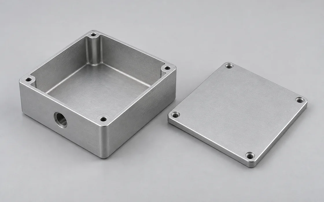
Electronic enclosures
An integral pocket and board bosses keep the PCB supports in one housing. For layouts still changing, separate spacers make a mounting-height change easier than remachining the enclosure floor.
Discuss this component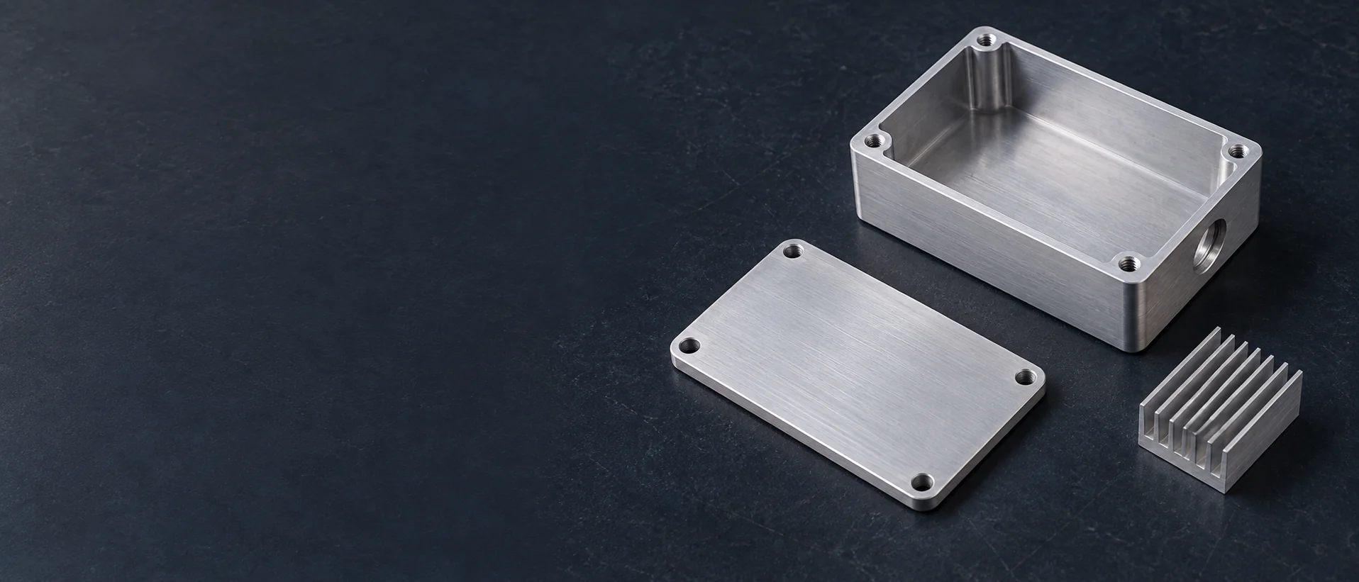
We machine custom enclosures, heat spreaders, connector mounts and PCB supports for electronic equipment. We supply the mechanical parts for your board layout, including pockets, mounting heights and external interfaces that a standard housing cannot accommodate.
Our parts connect the board layout to the finished instrument: the PCB must enter the housing, its connectors must meet the panel, and the cover must close without loading components or cables.
An integral pocket and board bosses keep the PCB supports in one housing. For layouts still changing, separate spacers make a mounting-height change easier than remachining the enclosure floor.
Discuss this component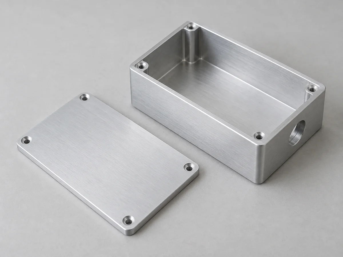
A separate machined panel lets you change display and connector openings while retaining the main housing. Recessed areas can accommodate connector mounting thickness without thinning the whole panel.
Discuss this component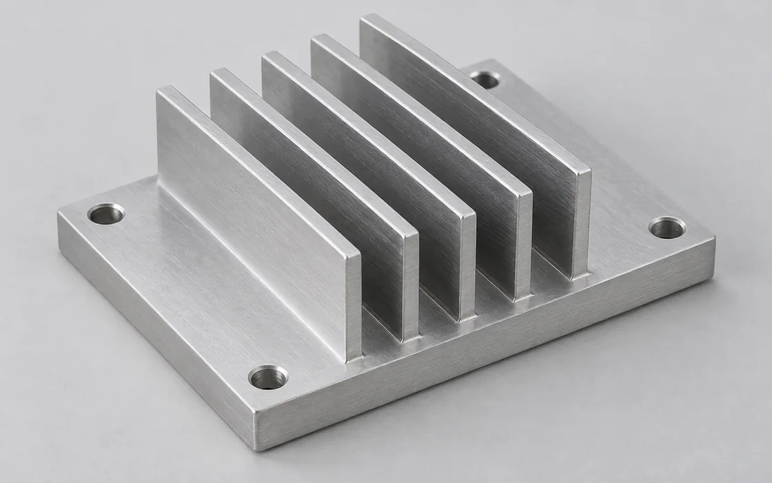
We machine heat-spreader plates and bases with mounting steps and component reliefs. A thicker base can distribute heat and resist bending, but it also adds weight and does not compensate for a poor contact joint.
Discuss this component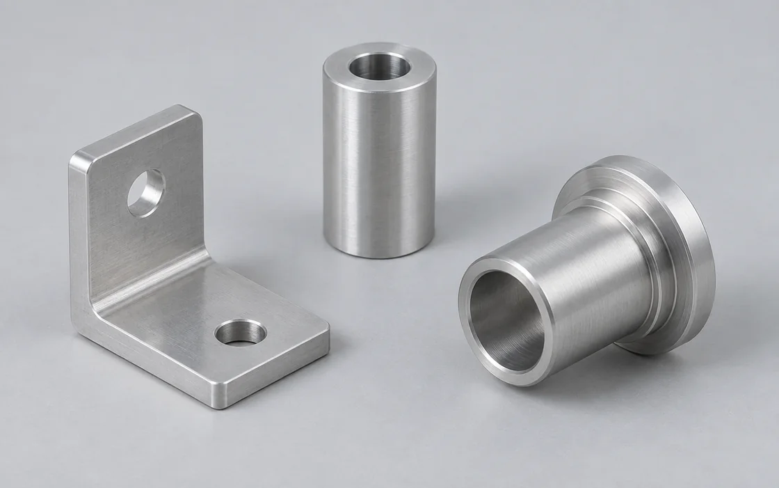
Connector sleeves, mounting blocks and bulkhead adapters connect purchased hardware to the housing. Their locating shoulders carry the mechanical position so the PCB connection does not have to absorb an enclosure mismatch.
Discuss this component
Spacers set the PCB height above the base. Separate supports also keep a replacement board at the intended connector height; using a taller fastener alone does not establish that distance.
Discuss this component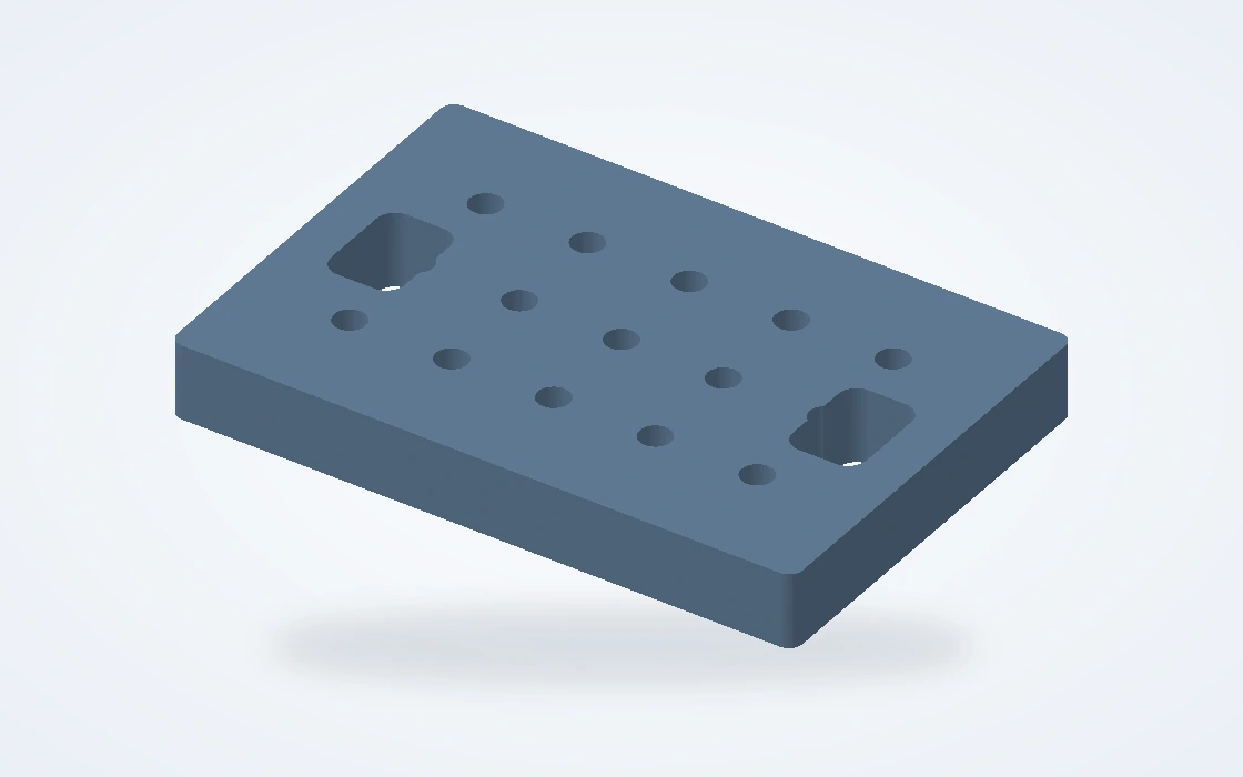
We machine nests, locating plates and support blocks for assembly and test stations. Support beneath screw-driving or insertion points keeps those operations from loading an unsupported board or thin housing wall.
Discuss this componentThese three applications need different machining priorities: a housing must accept the populated board, a thermal base must maintain contact, and a fixture must leave the operation accessible.
Board-edge connectors can prevent a PCB from dropping vertically into a close-fitting pocket. A removable end panel or an open insertion path gives the connector room to enter without enlarging every enclosure clearance.
Check the populated board and mating cable plug, not only the bare PCB outline. A connector may clear its cutout while its latch, backshell or cable bend still collides with the cover.
Use a drop-in cavity when the board clears the walls; use an end opening when projecting connectors need a sliding assembly path.
Leave room for the driver and mating plug after the board is fitted. A recessed screw behind a tall component may be unreachable in the assembled unit.
The spreader needs to meet the module over the intended contact area. A pad can accommodate a designed gap; grease serves a thin joint and should not be treated as a substitute for missing metal or an excessive step.
Select the interface material with the module and cooler, then set the machined heights around it. An uneven bolt pattern or a bowed base can leave one region lightly loaded even when the screws are tight.
Different component heights may need stepped contact lands or separate interface pads. A single flat plate can miss the lower components.
Mounting bosses or hard stops can limit pad compression. Their height must suit the selected interface layer rather than prevent the thermal faces from meeting.
A repeatable nest locates the housing from its mounting faces while leaving sockets, test pads and screw heads accessible. Avoid using a removable cover edge as the only location when the operation is performed with the cover off.
An asymmetric locator or stop can make a reversed loading position visibly incorrect before the operation starts.
Place support near an insertion or fastening load. Keep clamps clear of board components and connector bodies so the tooling does not create the damage it is meant to prevent.
A replaceable nest lets related board or housing versions share a base plate. Keep the base mounting pattern stable and change the part-contact details.
Each build should close a different uncertainty before more parts are ordered: physical fit, the finished assembly, then repeatability of the released configuration.
Start with the actual board and purchased connectors. Check insertion, cable mating and screw access while pocket dimensions and mounting heights are still economical to change.
Include the intended coating, thermal interface and fastening hardware in the pilot assembly. A bare-metal fit check will not expose a coated cover that binds or a contact area that has been insulated.
We quote repeat batches against the released configuration. Keep experimental connector layouts separate from that release so an untested panel change does not enter the next production order.
Choose the material by the component’s job. A conductive heat spreader, an isolated board support and a wear-resistant fixture contact do not need the same stock.
| Material | Component use | Choose for / watch for |
|---|---|---|
| Aluminum | Housings; panels; heat-spreader bases | Low-weight housing; isolate conductive contacts from anodizing |
| Steel / stainless steel | Fixture contacts; threaded supports | Wear or load-bearing details; check magnetic constraints |
| Copper / brass | Spreader plates; threaded connector details | Copper for heat transfer; brass where the specified interface calls for it |
| Engineering plastics | Insulating spacers; replaceable fixture nests | Electrical isolation; match grade to temperature and exposure |
The largest cost differences often come from pocket depth, tool access and the number of faces that need accurately related features. Those choices matter more than adding a tight tolerance to every outside surface.
A larger internal radius allows a larger cutter into an enclosure pocket. Keep a small radius only where the installed hardware needs it; a square-cornered module may instead use a local corner relief.
CNC milling servicesA turned spacer puts the seating faces and threaded connection around one axis. Where a wrench must hold it during assembly, flats provide access without relying on friction against the finished outside diameter.
CNC turning servicesSide connectors and top mounting features need a common reference. If an angled opening is only needed for cable clearance, compare that geometry with a simpler straight opening before adding a more complex setup.
5-axis machining optionsConcentrate dimensional control on the interfaces that meet. Unrelated cosmetic walls usually do not need the same limits as the PCB supports, panel connector or thermal seat.
The support height, PCB thickness and connector position form one dimensional chain. Control them from the board seating plane so the connector meets the opening without bending the board.
Specify flatness over the actual thermal footprint, not only the whole plate. Surface texture and burrs also matter there; a thickness measurement alone cannot identify a hollow or tilted contact area.
Anodized aluminum is electrically insulating at the surface. Mask the intended grounding pads or select a specified conductive treatment; do not depend on an ordinary screw scraping through the coating to form the contact.
A broad cover can distort when screws pull it down unevenly. Control the seating ledge and fastening arrangement, and distinguish free-state flatness from the assembled condition on the drawing.
Keep the external appearance, electrical contacts and fitted openings separate in the finish definition. One all-over finish can conflict with the other two functions.
Break edges around cable entries and hand-access openings without rounding locating shoulders. Internal pocket edges also need attention where a cable can rub against them during assembly or service.
Coating changes the finished size of bores, slots and threads. Mask a critical fit or allow for its specified coating rather than enlarging it by hand after the finished parts arrive.
Set the visible faces and acceptable tool marks before choosing cosmetic finishing. A hidden pocket need not receive the same appearance work as a front panel.
The useful inspection result is the one that catches an assembly problem before the board is installed. We identify the required component checks and records in the quotation.
Use the mating hardware or a defined gauge where fit is the acceptance question. Use dimensional or surface measurements where the result must remain comparable across later revisions.
| Record or check | Assembly risk | Useful check |
|---|---|---|
| Board and module locations | Board bows or connector sits off-center | Support heights and cutout position from board datums |
| Connector and cover interfaces | Hardware enters but cannot latch or seat | Selected connector or defined mating gauge |
| Thermal contact face | Part of the thermal footprint lifts clear | Footprint flatness, texture and burr condition |
| Finished surfaces | Coating blocks fit or electrical contact | Post-finish fits and masking boundaries |
| Part and material records | Wrong panel or spacer variant reaches assembly | Part/revision match between labels and records |
The machined part can meet its drawing while the device still needs thermal, electrical or EMC changes. Evaluate those functions on the populated, fastened assembly; component dimensions alone do not establish system performance.
We arrange packing around the surfaces that need to arrive ready for the next assembly step.
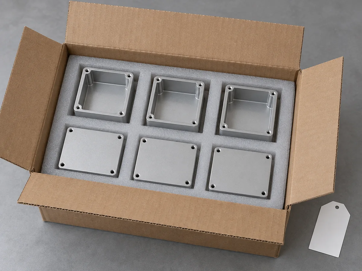
Separate covers from housings and protect the thermal footprint from scratches or adhesive residue. Packing against a nonfunctional outside face avoids loading a thin panel or contact land.
Label connector-layout variants and spacer heights separately. Two parts with the same outside envelope can still place the board at different heights or block a cable connection.
For a housing-and-cover set, the packing list should distinguish the common housing from variant panels and supports. That makes missing build-specific parts apparent at receiving.
Consider a custom machined body when the assembly needs integral pockets, accurately related mounting faces or a shape that stock housings cannot provide. If a standard extrusion already fits the PCB, a custom end panel may solve the problem with less machining. A large, thin-walled cover is also worth comparing with sheet metal before choosing a solid-machined design.
A board outline can start the discussion, but Gerber files do not define populated component heights, the connector’s mating plug or the enclosure fastening. Add a mechanical assembly or enclosure model with those interfaces. We quote the mechanical component, not the board fabrication data.
Yes, if the board location, cover seat and panel fastening pattern remain common. Keep those shared interfaces fixed and release each cutout pattern as a separate panel variant. A change to the board loading path or connector depth may require another housing version rather than an interchangeable panel.
Often the functional interfaces can be retained, but thin snap-fits, inaccessible undercuts and sharp internal corners may need different geometry. Agree which features the prototype is meant to test. A screwed cover can support a fit check without demonstrating the behavior of the later molded snap-fit.
Direct tapped holes keep a lightly serviced housing simple. Where the cover will be removed frequently, a specified metal insert can provide a wear-resistant screw connection in an aluminum body. The boss still needs enough material for the insert’s installation diameter and depth; adding an insert after the housing is machined may leave too little wall.
No. Openings, seams, seals, cables and the final assembly affect protection and electromagnetic behavior. IEC 60529 addresses enclosure ingress protection; the specified rating must be evaluated for the complete enclosure configuration. A dimensional report is evidence about the part, not a substitute for those evaluations.
Compare the complete cost after the design is stable. A standard extrusion with machined ends may suit a constant cross-section; casting or molding may become relevant when tooling can be justified. CNC remains useful for changing variants and features that still need finish machining. There is no single order quantity at which every enclosure should switch processes.
We supply custom mechanical parts and tooling. PCB fabrication, wiring and electronic assembly remain with your electronics supply chain. That separation lets you order the housing, thermal parts or fixture components without purchasing a complete instrument from us.
Technical references for contact surfaces, anodizing and enclosure classification.
Share the mechanical component and the board or hardware it must fit. We will quote the machining and finish for your required build quantity.
Enclosure, panel or interface drawing with the relevant hardware layout.
Component quantities, configuration and current revision.
Material, contact and cosmetic requirements, requested records and target date.
An early enclosure model can start the manufacturing review.