Mounting brackets
We mill base faces, upright webs and fastening holes in 2024 brackets. Relief pockets follow the drawing around the ribs and bosses that connect the mounting surfaces.
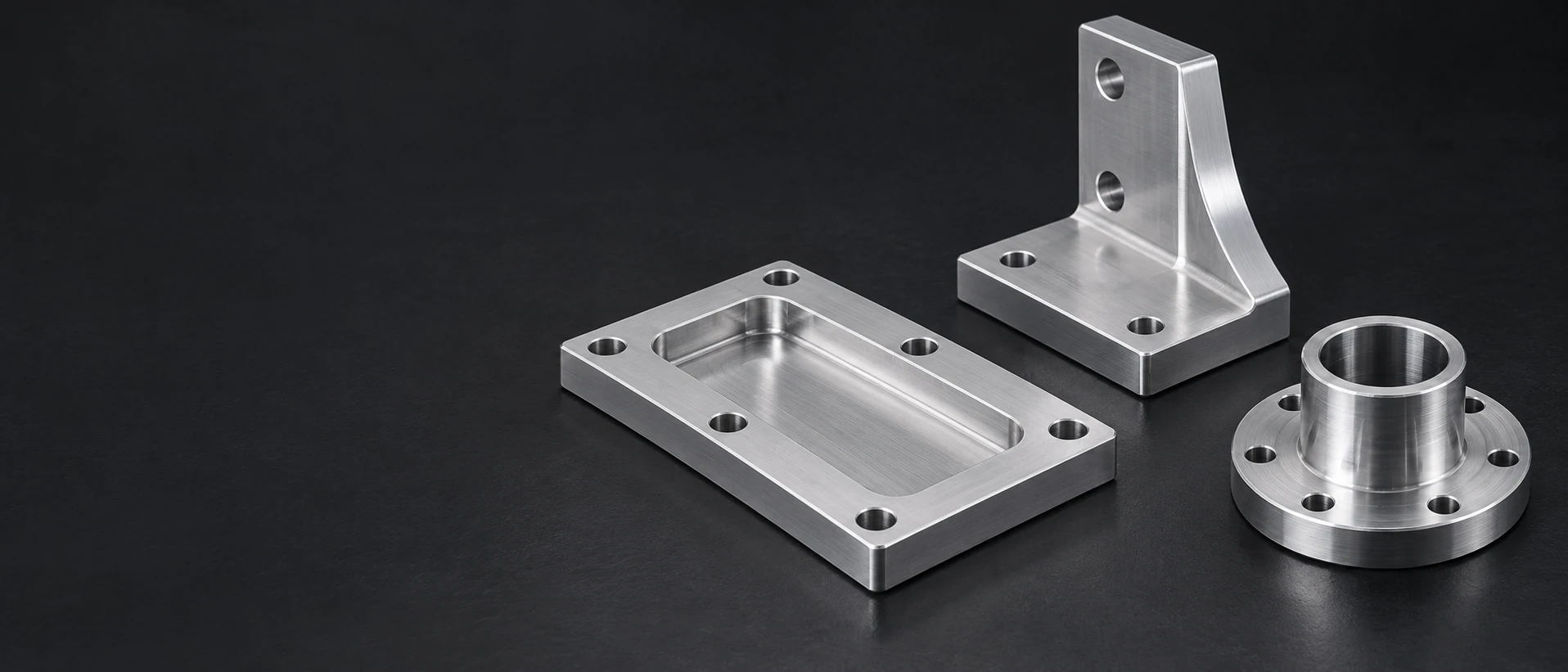
We mill base faces, upright webs and fastening holes in 2024 brackets. Relief pockets follow the drawing around the ribs and bosses that connect the mounting surfaces.
Mounting plates combine a working face with hole patterns, counterbores and locating features. Milled steps can provide separate seats for components mounted at different heights.
A turned hub brings its bore, flange face and locating register onto a common rotational axis. We machine the bolt pattern, slots or flats needed to connect that profile to the surrounding assembly.
Spacer sleeves use a bore and two end faces to establish an axial separation. Shouldered versions also provide a locating diameter or a stop for the mating component.
We machine open cavities, cover seats and mounting bosses in 2024 housings. Cable openings, internal steps and attachment details form part of the same drawing-defined body.
A clevis combines paired lugs, aligned pin bores and space for the mating link. A single-lug component uses its bore and surrounding section to form the attachment interface.
Our 2024 machining service covers drawing-defined milled and turned components, with the stock condition, finish and inspection scope identified for the order.
The stock form belongs with the temper designation. AMS4037 identifies 2024-T3 flat sheet and T351 plate; a sheet-based component and a deeply pocketed plate component therefore start from different material definitions. [2]
In the same original plate-thickness band, T851 has higher minimum tensile and yield strengths but a lower minimum elongation than T351. The temper choice therefore includes both strength and ductility requirements. [1] [2]
A plate blank accommodates mounting faces, pockets and lugs across a wide envelope. The original stock thickness and material direction remain relevant to its property requirements after the exterior and cavities have been machined. [2]
Round bar can reduce the material removed around a hub or sleeve. Rectangular bar can suit a repeated milled section. Their product specifications and temper-dependent properties remain separate from those of plate.
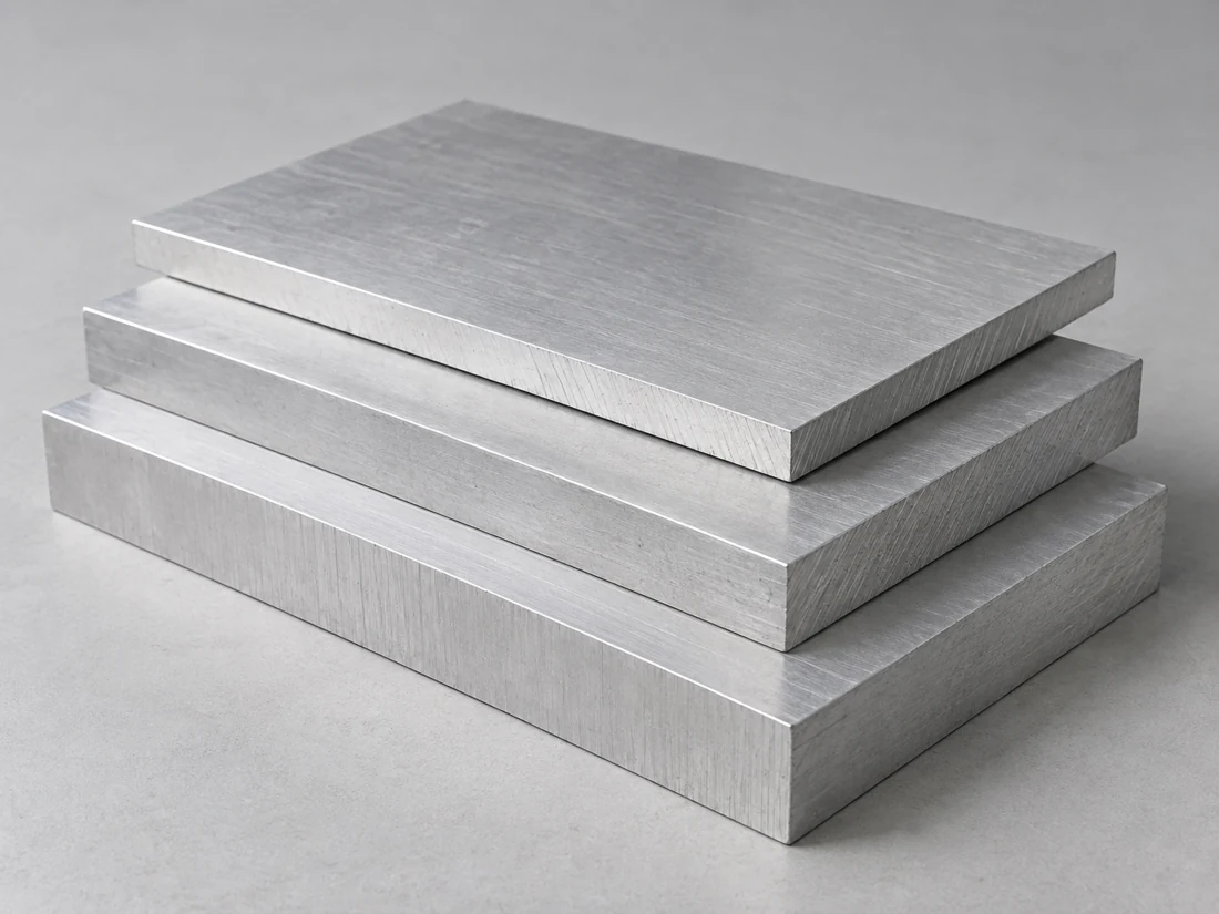
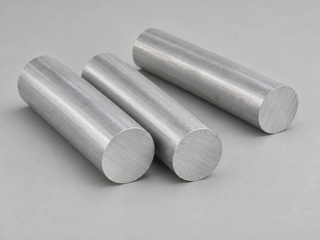
A higher yield strength delays permanent deformation, but it does not make the elastic modulus rise by the same amount. The T351 and T851 values below have the same modulus. For a slender support or plate, its span, thickness and support arrangement still determine how it deflects. [1] [2]
The mechanical limits compare unclad plate in the same original stock-thickness band.
| Property | 2024-T351 | 2024-T851 | Reference basis |
|---|---|---|---|
| Ultimate tensile strength (ksi) | 64 | 67 | Reference minimum |
| Yield strength (ksi) | 42 | 58 | Reference minimum |
| Elongation (%) | 12 | 5 | Minimum; 2 in or 4D gauge length |
| Applicable original plate thickness (in) | 0.250–0.499 | 0.250–0.499 | Unclad stock; not finished-part size |
| Elastic modulus (GPa) | 73.1 | 73.1 | Producer typical |
| Density (g/cm³) | 2.77 | 2.77 | Nominal at 20°C |
| Linear expansion (µm/(m·K)) | 22.9 | 22.9 | Mean over 20–100°C |
Sources: Kaiser Aluminum, Sheet & Plate, Table 7.2 (Aluminum Standards and Data 2006), supplies the three mechanical-property reference minima for unclad plate in the stated original thickness band. The 2024 Sheet, Coil & Plate Technical Data, Rev. 05/06, supplies the typical or nominal physical properties. Actual stock acceptance follows the ordered product specification, and design allowables come from your own engineering basis.
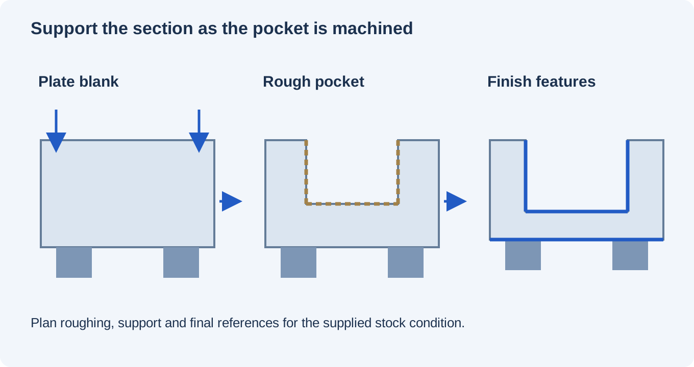
We mill cavities, mounting seats and hole patterns in 2024 bodies. As a solid blank becomes an open pocket, the remaining floor and ribs provide less support against cutting forces; the finishing route must suit that lighter section.
Bores, shoulders and sleeve profiles begin with rotational features. A slot, cross-hole or flat then adds another machining orientation, so its relationship to the turned axis remains part of the component definition.
T351 can still move after a thin wall or pocket has been machined. Residual stress, cutting conditions and clamping all affect the released shape. Roughing and finishing may need separate support or datum establishment; holding a moved part flat can conceal the movement rather than remove it. [3]
Drawing limits apply to the specified measurement and delivery condition.
| Feature | Requirement or reference | Accepted condition | Verification |
|---|---|---|---|
| Pin bore or locating register | Drawing size and datum relationship | Specified final interface | Dimension and datum-based position check |
| Pocketed mounting face | Drawing flatness / parallelism | Released or specifically defined support | Surface measurement without forcing it flat |
| Temperature-sensitive span | 100 mm, 20→40°C: ΔL ≈ +0.0458 mm | Published mean coefficient treated as constant | Calculation; assembly clearance also uses mating parts |
| Protected thread or fit | Specified final size and treatment boundary | Delivered coating and masking state | Applicable thread or dimensional check |
Thermal calculation: ΔL = αLΔT, with α = 22.9×10⁻⁶/K, L = 100 mm and ΔT = 20 K, using the producer’s 20–100°C mean coefficient as constant for the stated temperature change. It describes material expansion, not a machining tolerance. The drawing defines the actual finished limits.
The required size, datum relationship and surface condition govern the finished feature. We quote against those controls rather than applying one tolerance to every 2024 wall, bore and overall span.
A radiused pocket corner provides access for a rotating cutter. If a mating part needs a sharper corner, a relief or a different feature arrangement can provide clearance without changing the whole pocket profile.
A screw seat needs a load path into the surrounding body. A narrow unsupported rim may deflect under clamp load even when the adjacent wall is dimensionally correct; a retained boss or land places the seat over a supported section.
A lug can place sustained tensile stress across the stock’s grain direction. In a corrosive environment, that orientation matters to 2024’s stress-corrosion behavior. A strength value without its product and direction basis cannot describe every attachment orientation. [1]
A blind tapped hole needs space for its usable thread and the tool’s runout beyond it. Screw length, surrounding wall and access from the assembly determine whether the intended engagement is physically available.
An instrument bracket may locate a sensor from one face while its mounting screws sit on another. Keeping those interfaces in one datum scheme prevents a correct bolt pattern from concealing a shifted instrument seat.
A fixture plate can combine a fixed locating pattern with slotted adjustment. Separating those functions lets an assembly be aligned without treating the clearance in its fastening holes as a repeatable locating feature.
A hub flange or spacer end should reach its intended shoulder. Corner radii, chamfers and coating boundaries at that junction can prevent full seating, changing the installed axial position even when the overall length is correct.
Internal equipment needs cavity clearance as well as cover and mounting seats. Where an interface also carries electrical contact, its exposed or treated contact area has a different function from a purely cosmetic exterior.
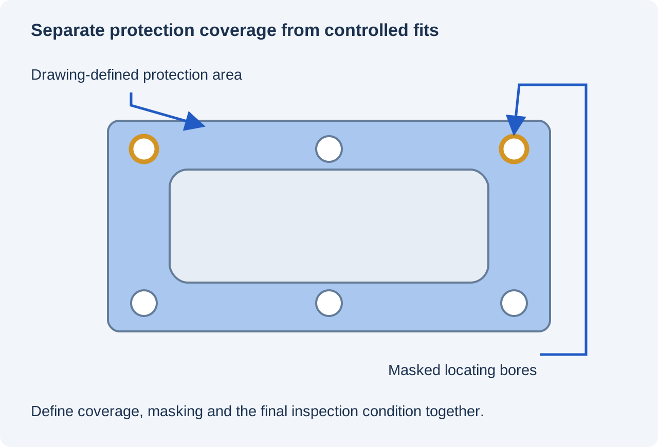
2024’s copper-rich composition limits its corrosion resistance. Anodizing, conversion treatment and a compatible primer or paint system serve different protection and finishing requirements. The selected system follows the component’s environment and surface function.
Masking keeps a selected fit or conductive contact separate from adjacent treated areas. The drawing’s boundaries need to follow the actual working land so that exterior protection does not obstruct its mating function.
Burr removal protects pin entrances, pocket rims and adjacent surfaces from loose or sharp edges. Treatment access into a recess and protection at an exposed edge are separate from the size of the edge break.
Temper and preparation can affect the appearance after anodizing. Where parts must match visually, the finish reference applies to the chosen material and surface preparation rather than assuming that every 2024 part will have the same color.
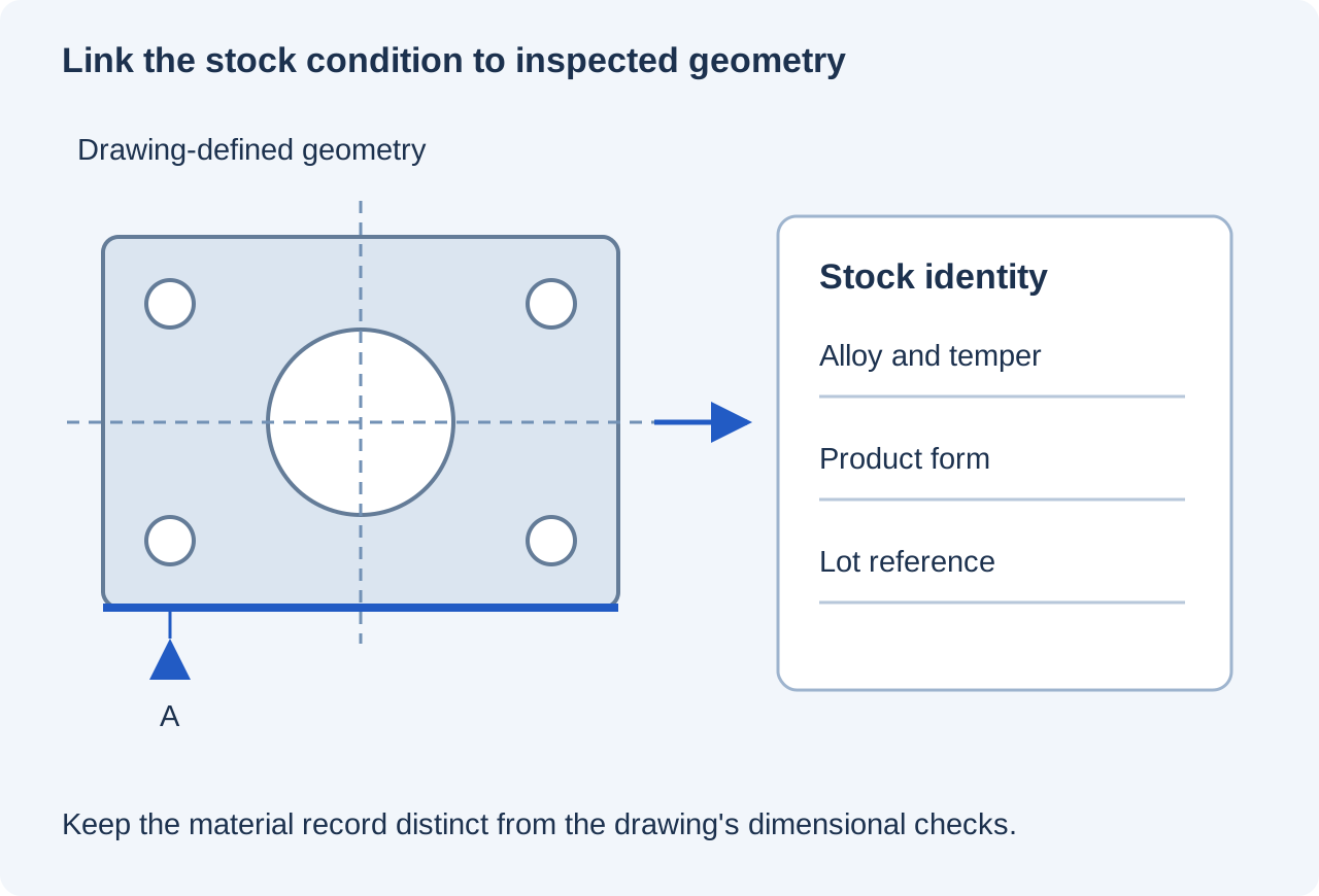
The stock record identifies the actual 2024 product form, temper and ordered specification. A generic alloy name or a producer’s typical-property table cannot identify the batch from which the part was cut.
We inspect the selected dimensions and datum relationships in the defined delivery condition. A machining-stage result remains distinct from a result taken after a later coating or thermal operation.
A load, fatigue or other functional requirement needs a component-level method and acceptance basis. That result comes from the component-level method, and any validation we supply is identified in the quotation.
A close-fitting round blank can reduce removal for a sleeve, while a wide bracket or pocketed housing needs a different section. Required stock orientation and the shape left around the part affect the amount purchased and cut away.
Large cavities take time to remove, but the remaining geometry can matter just as much. Thin walls, long tool reach and features on several faces add support or setup work beyond a simple comparison of metal volume.
Masked lands, surface preparation and a specified appearance add defined finishing operations. Recording selected feature results or performing a separate component test adds its own work to the machining route.
Programming and initial fixture preparation are shared across the quantity produced together. A repeat using the accepted drawing and stock definition can reuse that basis; a changed temper, blank form or interface may require new preparation.
The initial component establishes access, assembly sequence and fit with the actual mating parts. An installation trial can reveal a clearance change before that geometry is carried into a production drawing.
The first-part result establishes the accepted feature measurements and any specified finish reference. Changes made after the trial become part of the released definition rather than an undocumented adjustment.
The released drawing, material condition and included checks define the batch to be made. A change to the stock form or final treatment is resolved against that baseline before it is applied to the quantity.
An unchanged repeat retains the accepted interface and delivery definition. If a mating component, service environment or material condition changes, the affected features are assessed as a revision to that part.
Not automatically. T3511 identifies an extruded product condition, while the plate and extrusion are covered by different product specifications and property requirements. A proposed change must fit the drawing’s accepted material basis, including the relevant section and direction, rather than relying on the shared 2024 alloy number.
No. Yield strength, ultimate tensile strength and elongation are separate acceptance requirements. For the plate band shown, T851 has higher strength minima but a lower elongation minimum than T351. If the ordered material must satisfy all three limits, an acceptable yield result cannot compensate for an unacceptable tensile-strength or elongation result.
No. Aging changes the material condition, and a thermal operation can affect the finished geometry. A proposed route needs an approved property basis and the dimensional checks required after that operation. A T351 inspection result should not be relabeled as acceptance of a later T851 component.
No. AMS4037R identifies 2024-T3 flat sheet and T351 plate; T851 is outside that stated temper scope. A T851 component needs a purchase specification that covers its actual product and condition. Comparing the two tempers on this page does not extend AMS4037 to cover both.
Not as a drop-in material change. Copper-containing 2xxx alloys are difficult to weld by conventional arc methods, and the joint’s final properties need their own qualified basis. The material choice and joining route should be resolved together instead of using the incoming stock strength as the strength of the weld.
Not unchanged. For the footnoted Alclad 2024 plate values at 0.500 in and thicker, Kaiser specifies test specimens with the cladding removed. Those values describe the core; the full clad plate has slightly lower tensile and yield strengths, depending on cladding thickness. A part that retains cladding needs the applicable composite-section property basis.
Send the matching model and drawing, required 2024 stock specification and temper, quantity, finish and inspection scope. We will quote the drawing-defined part and its delivery requirements.
Sources for the stated material conditions, manufacturing effects and protective-surface distinctions.
We use Google Analytics to see how this site is used. Analytics cookies are set only if you accept. Privacy Policy
