Electrical standoffs
We turn the body, end faces and fastening features of PEI standoffs. Shoulders, through-holes or end threads follow the drawing’s arrangement for separating and supporting the mounted components.
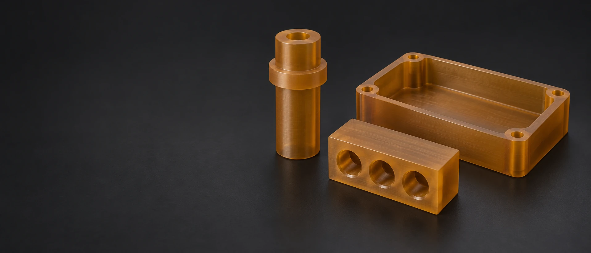
We turn the body, end faces and fastening features of PEI standoffs. Shoulders, through-holes or end threads follow the drawing’s arrangement for separating and supporting the mounted components.
Insulating terminal blocks combine contact pockets, mounting faces and separate conductor openings. We mill the channels, seats and hole patterns that locate the specified terminals within the PEI body.
A flanged PEI sleeve uses its bore and outside diameter to separate mating components, with a flange for axial seating. Internal steps, lead-ins and shoulder reliefs form part of the turned profile.
We mill mounting feet, sensor seats and fastening holes in PEI brackets. Open slots, stepped faces or cable clearances can be included where the component drawing provides them.
A carrier plate combines locating holes, pockets and supporting lands for the item being handled. We machine the specified working face and its mounting pattern into the selected PEI stock.
PEI instrument bodies can combine an open equipment cavity, cover seat and mounting bosses. Accessible passages and cable openings are machined around the sections retained to support those interfaces.
VETCNC quotes custom milled and turned PEI parts from a specified machinable stock grade. We confirm sourcing, feature feasibility, finishing and the included records for the order.
Unfilled PEI is a candidate where the part needs an insulating body without glass reinforcement. In the named stock comparison below, U1000 has substantially more elongation at break than U2300. That difference matters to a retained lip or other feature that must tolerate assembly movement. [1]
Thirty-percent glass reinforcement raises the modulus and reduces the published thermal expansion in the U2300 comparison. It also reduces elongation at break; the ASTM tensile-strength entries happen to be equal. A stiffness improvement therefore does not mean that every strength or assembly requirement improves. [2] [1]
Rod can reduce the removal needed for a standoff or sleeve, while plate suits a terminal block, bracket or carrier. A stock-form change can alter the material history behind the part; the required stock product and any direction-dependent acceptance remain part of the specification. [3]
PEI names the polymer family, while ULTEM identifies a resin family used in machinable stock products. A drawing that requires a particular formulation or stock source retains that identity. The Duratron values below describe those named stock products, rather than every material sold as PEI.
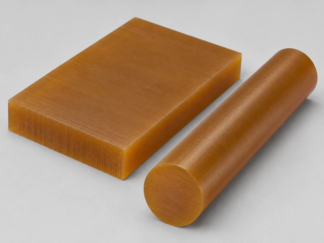
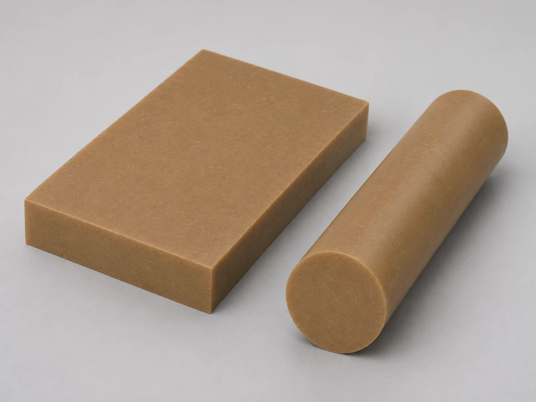
The HDT row compares deflection in a test at 264 psi. It helps distinguish the products under that test condition. A mounted support also has its own load, wall geometry and exposure time, so the final design uses those conditions alongside the reference data. [1] [2]
The comparison uses the same producer’s ASTM columns for two dry PEI stock products.
| Property | Duratron U1000 | Duratron U2300, GF30 | Test basis |
|---|---|---|---|
| Tensile strength (psi) | 17,000 | 17,000 | ASTM D638 |
| Tensile modulus (ksi) | 500 | 800 | ASTM D638 |
| Elongation at break (%) | 32 | 3 | ASTM D638 |
| Heat deflection temperature (°F) | 400 | 410 | ASTM D648; 264 psi |
| Linear expansion (µin/in/°F) | 31 | 11 | ASTM E831; −40–150°C |
| Dielectric strength (V/mil) | 830 | 770 | ASTM D149 |
| Water absorption after 24 h (%) | 0.25 | 0.18 | ASTM D570; water at 23°C |
Source: MCAM Duratron U1000 and U2300 PEI Product Datasheets, printed revision 07/03/2023, ASTM columns. Values describe dry named stock products for comparison. Mechanical data are mainly averages from specimens machined from 40–60 mm rod, or 10–20 mm plate when rod is unavailable, at 23°C. Direction is unstated. D570 uses 1/8 in thick specimens. These values are not guaranteed purchase minima or finished-component ratings.
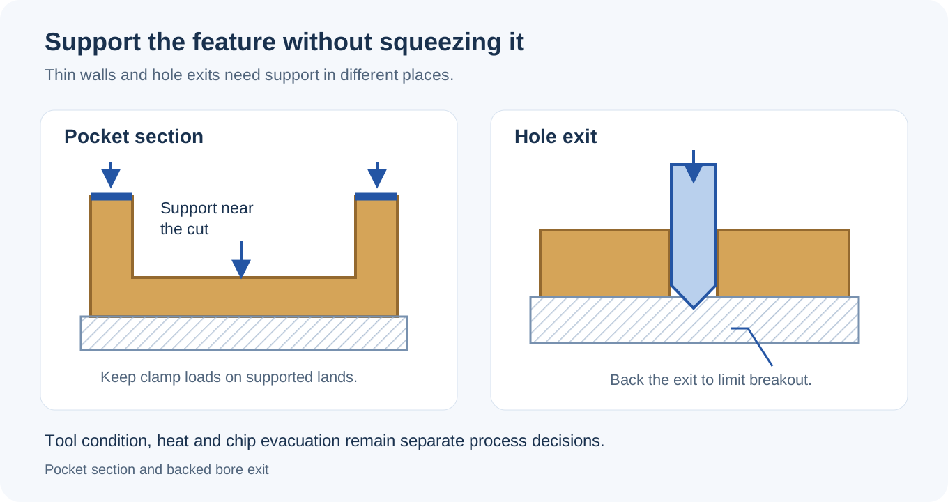
We mill terminal seats, equipment cavities and mounting patterns with support beneath the retained section. As pockets open up, the remaining floor or wall becomes easier to deflect. Heavy clamping can conceal that deflection during the cut.
Turning brings the sleeve bore, outside profile and seating faces onto the intended axis. A thin sleeve wall or narrow flange needs support that does not squeeze it into a different shape while the fitting surfaces are machined.
Glass-filled stock is abrasive. Cutting-edge wear can change heat generation and the condition of hole exits or pocket edges, so the finishing plan includes suitable tooling and checks on edge quality. The unfilled and reinforced grades need their own cutting plan. [3]
Finished limits apply in the drawing’s specified support, temperature and conditioning state.
| Feature | Requirement or reference | Accepted condition | Verification |
|---|---|---|---|
| Standoff or mounting land | Drawing height and face relationship | Specified free or fastened state | Length/face check in that state |
| Flanged insulating sleeve | Drawing bore, outside fit and flange seat | Loose or installed condition as defined | Bore and seating check |
| Unfilled U1000 reference span | 2 in, 73→123°F: ΔL ≈ +0.0031 in | Published mean coefficient held constant | Material calculation; assembly also uses mating parts |
| Conditioned or cleaned feature | Drawing dimension and surface requirement | After the agreed conditioning/cleaning sequence | Final feature and surface inspection |
Thermal calculation: ΔL = αLΔT, using U1000 α = 31×10⁻⁶/°F, L = 2 in and ΔT = 50°F. The source coefficient is a −40–150°C mean; the estimate covers unreinforced stock in one direction. Reinforced-stock orientation effects and installed clearance are worked out from your design, and acceptance follows the drawing’s specified state.
We quote the selected sizes and datum relationships for the actual PEI grade and geometry. Final acceptance identifies whether the part is free, supported or assembled; there is no single accuracy value that describes every sleeve wall, mounting plate and instrument body.
A bolt head or washer needs enough land beneath it to spread the fastening load. A boss tied into the body supports that contact more effectively than a thin, unsupported pocket rim.
A contact pocket, cross-hole and fastener can compete for the same remaining section. The drawing needs a continuous material path around those openings, with enough access to remove burrs at their intersections.
A counterbore exposes the fastener head within the part. Metal washers, inserts or a through-bolt can bridge components that the PEI body is intended to separate, so their positions belong to the complete insulating layout. [4]
A rotating cutter leaves an internal corner radius. The cover or inserted equipment needs clearance at that corner, while the seating land remains wide enough to perform its locating function. A relief can solve local interference without changing the whole cavity.
An insulating standoff positions the mounted component away from a metal base. Its shoulder and fastening arrangement define that separation; an ordinary part drawing still needs the assembly’s applicable electrical design and acceptance requirements.
A terminal block locates the contact and provides space for its connection. Contact seating, wire approach and tool access must fit the surrounding enclosure rather than relying only on the outside block dimensions.
A sensor bracket locates the sensing face from the mounting datum while leaving space for its cable and connector. An accurate bolt pattern cannot compensate for a shifted sensor seat or a connector that cannot be reached after installation.
A carrier needs to locate the item during handling and then release it without interference. Pocket clearance, contact lands and locating stops have different jobs; only the surfaces used to locate the item need to serve as those references.
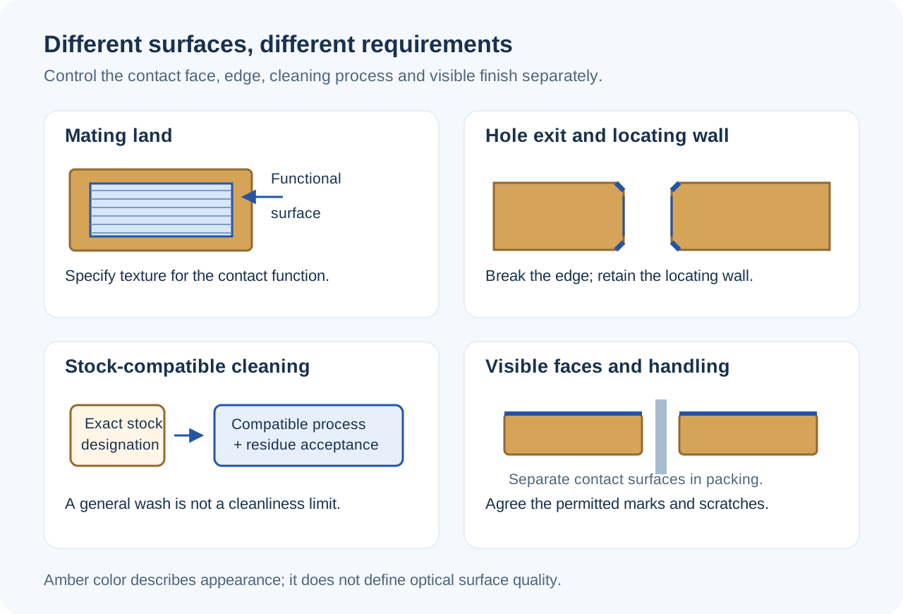
Bores, seating faces and contact pockets retain the specified surface texture and permitted tool marks. The mating land and the fit of an inserted terminal are each checked against the specified surface texture and permitted tool marks.
Burr removal clears hole exits and pocket intersections without rounding a locating shoulder or opening a fitted entrance beyond the drawing. On a reinforced grade, exposed-edge condition is assessed on the actual machined surface.
The selected cleaner and any process fluid must be compatible with the exact stock. Where the component enters a sensitive assembly, the order defines the required final cleaning and residue acceptance rather than assuming that a general wash is sufficient.
Unfilled amber PEI and amber-brown reinforced stock do not present the same appearance. Visible faces use the agreed mark and scratch criteria, with contact surfaces separated during packing. The material’s color is not an optical-quality specification.
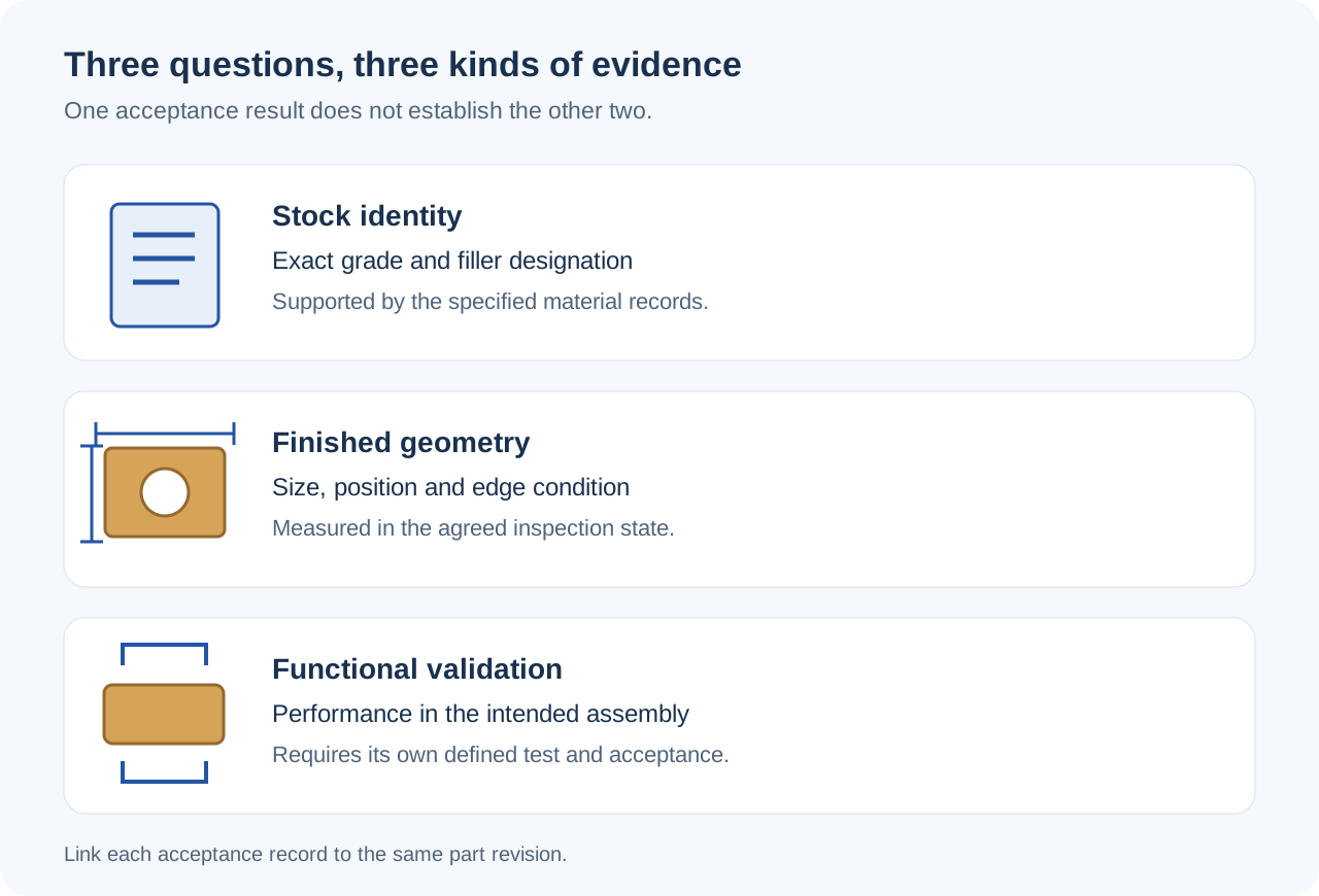
The material identity follows the ordered PEI product, reinforcement and any approved-source restriction. A general resin name does not demonstrate that the purchased stock has the same property basis as the reference product.
We inspect the selected features after the included finishing and conditioning steps. The measurement record identifies the component’s acceptance state so that a supported plate or installed sleeve is not compared with an unrelated free-state result.
An electrical, flame, cleanliness or other functional requirement needs its own applicable evidence and acceptance method. Those requirements are agreed separately; a material datasheet or dimensional report alone does not approve the assembled equipment.
A required stock producer, formulation or color affects sourcing. A rod close to a standoff profile uses material differently from a wide plate blank for a pocketed housing, even when both parts have similar finished volume.
Glass reinforcement adds tooling wear considerations. Thin walls, deep contact pockets and features on several faces can also add support and finishing work beyond the time needed to remove a given volume of polymer.
Controlled edge condition, selected appearance, cleaning and recorded features each add defined work. A functional test or source-specific material document is a separate item in the quoted scope, rather than an assumed property of any PEI order.
Programming and initial workholding preparation are shared across the quantity made together. An unchanged repeat can retain that basis; a different reinforcement, stock product or acceptance state may require another machining and inspection plan.
The first geometry trial checks terminal insertion, cover seating, fastening access and release from the fixture. It identifies where the drawing needs a change before the production definition is fixed.
The representative component uses the intended PEI product and included process steps. This stage checks that the accepted dimensions, edge condition and appearance can be obtained on that stock, rather than inferring them from a different formulation.
The released drawing, stock identity and final inspection condition define the batch. A change made during the trial becomes a recorded revision before the remaining quantity follows it.
Repeat orders retain the accepted product and part definition. A source, formulation or cleaning-process change is reviewed against the affected fit and functional requirements before it is carried into production.
Not from that entry alone. MCAM’s notes call the stock-shape ratings estimated and state that no UL File Number is available for these shapes. A requirement for recognized material or a certified end product needs the specific evidence required by that program; the comparison table cannot supply it.
No. It describes breakdown under a material test, with conditions such as specimen preparation, electrodes and surrounding medium. ASTM D149 cautions that results can seldom be applied directly to actual equipment. Working voltage and the complete insulating arrangement need their own applicable design and verification basis.
Its note defines an air-aging reference associated with about a 50% loss of tensile strength measured afterward at 23°C. It addresses thermal-oxidative aging. It is a different criterion from retaining an exact loaded dimension, and the permitted service condition also depends on stress and duration.
Those are MCAM’s separate ISO and ASTM test datasets. The notes identify different tensile-bar procedures and geometry, so the numbers are not a material acceptance range. Keep the chosen test method, stock product and condition together instead of selecting individual values from different columns.
Compatibility needs to be established for the selected fluid and stock. MCAM specifically warns that general-purpose petroleum cutting fluids may contribute to stress cracking of amorphous U1000 PEI. Suitability for a stressed PEI surface, and the required final cleaning process, are each confirmed for the selected fluid and stock in their own right.
Do not assume the two electrical functions are interchangeable. A carrier required to dissipate charge needs a specified resistance range and a formulation intended for that task. MCAM identifies Semitron ESd 410C as a purpose-modified dissipative PEI; that is a separate product choice from the U1000/U2300 comparison.
Send the matching drawing and model, required PEI formulation or stock product, quantity and final surface requirements. Include the critical dimensions and any defined electrical, conditioning or acceptance requirements so we can quote the intended component.
Named stock-product data and the manufacturing and test conditions used on this page.
We use Google Analytics to see how this site is used. Analytics cookies are set only if you accept. Privacy Policy
