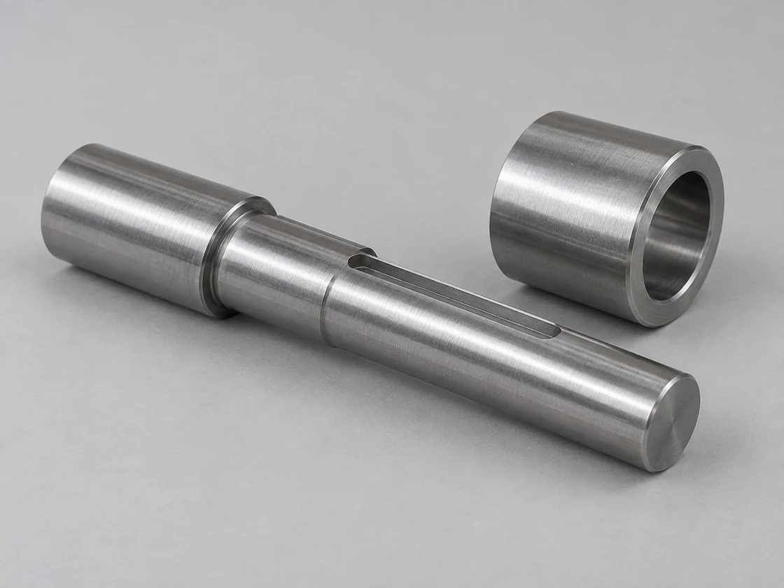
Pump-drive shafts
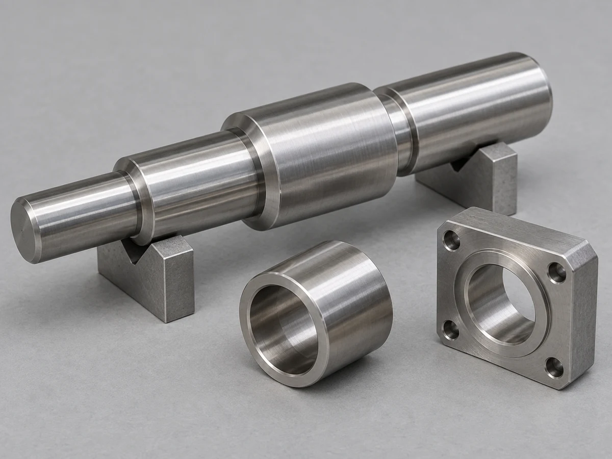
We turn the bearing and coupling seats on pump-drive shafts. Shoulder spacing determines where the rotating parts sit; runout between the seats affects whether those parts share the intended axis.
Discuss this component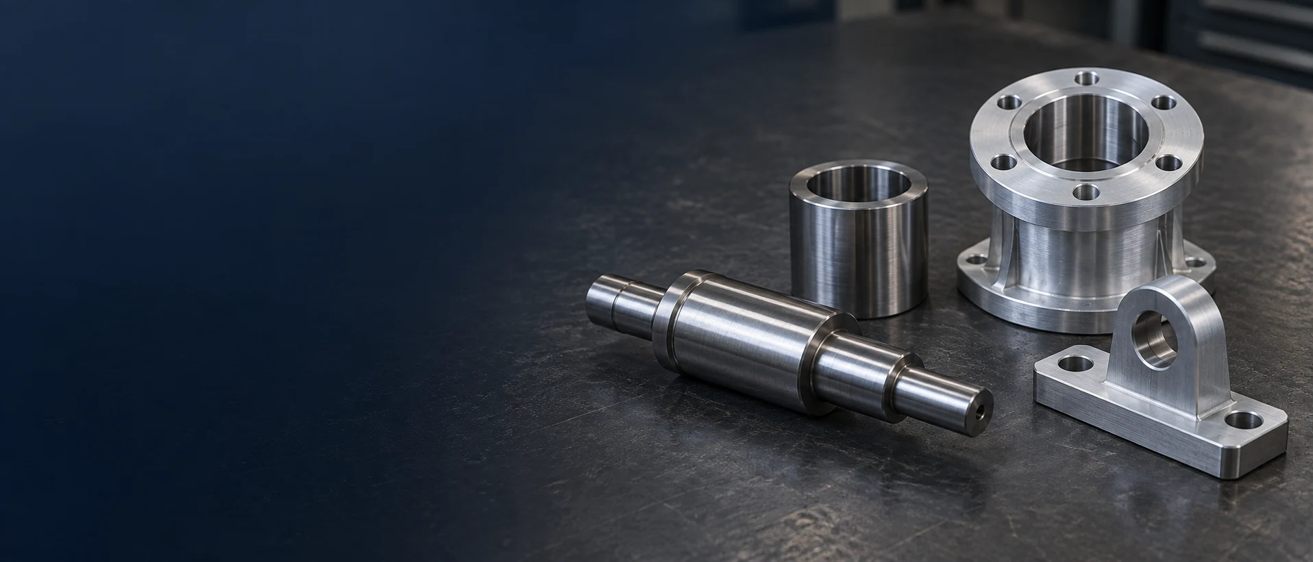
We machine shafts, replaceable sleeves, bearing housings and adapters for pump drives, generator auxiliaries and energy equipment. Our components connect new hardware to existing shaft, bearing and mounting interfaces, from assembly trials to repeat supply.
We supply the shaft, housing or mounting part as an individual component. Related parts can share one order where their fits and axial positions need to be checked together.
We turn the bearing and coupling seats on pump-drive shafts. Shoulder spacing determines where the rotating parts sit; runout between the seats affects whether those parts share the intended axis.
Discuss this component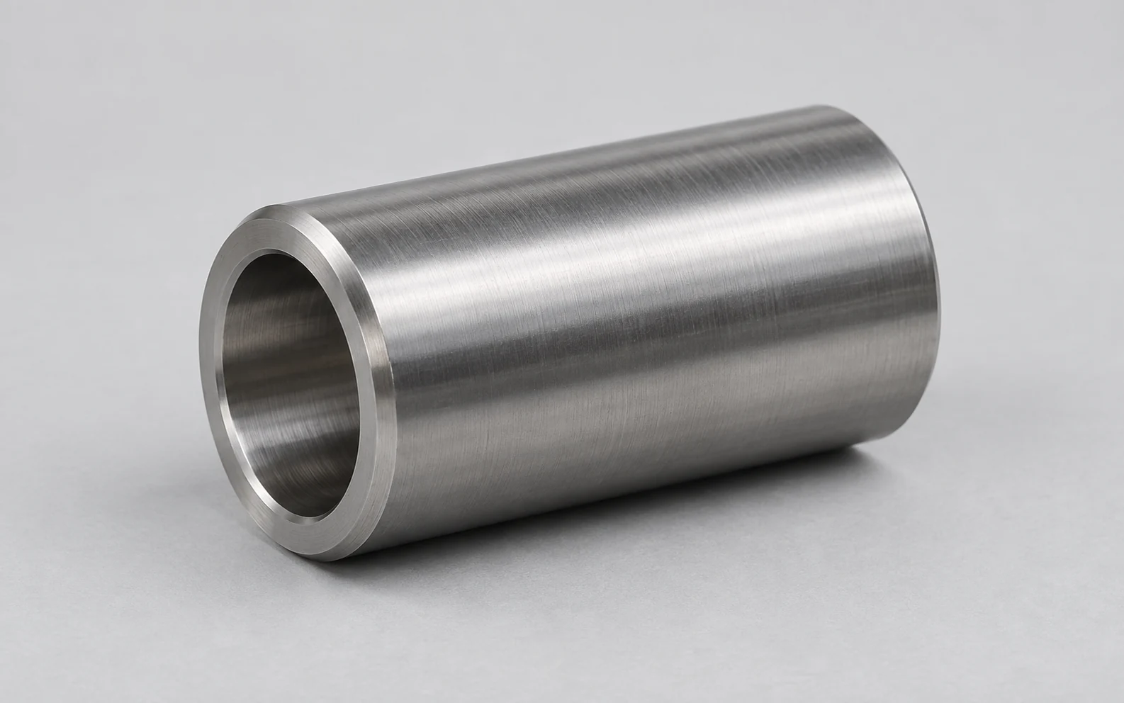
A replaceable sleeve puts the wearing contact surface on a separate part. Its bore must fit the retained shaft, while its outside diameter matches the seal or bearing that runs against it.
Discuss this component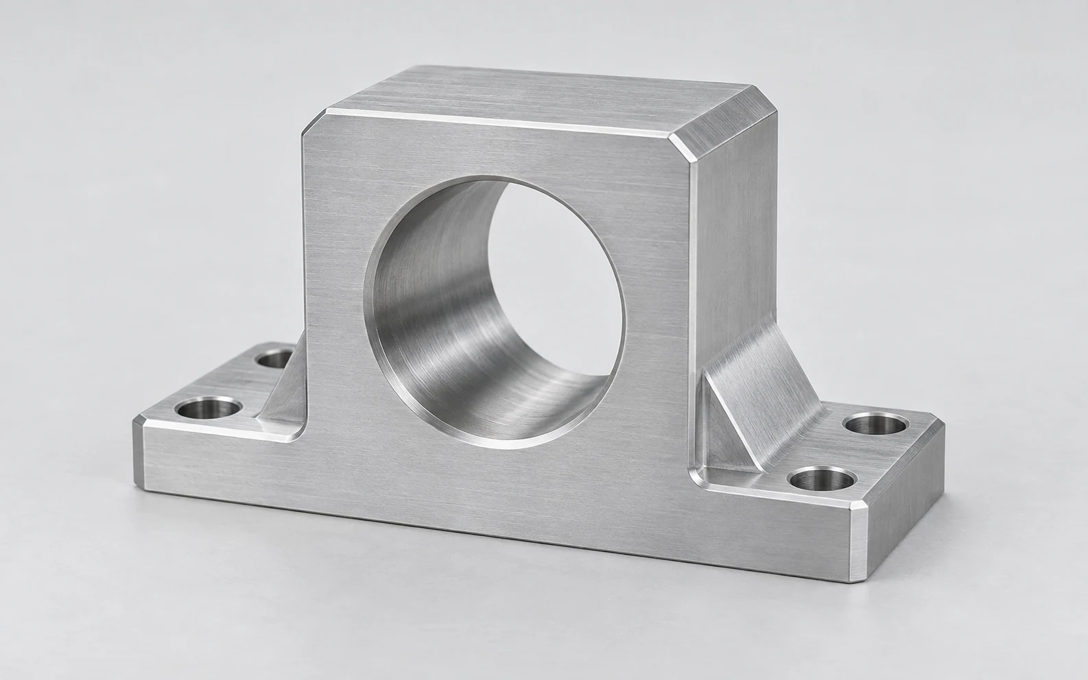
We machine bearing housings with bores related to their mounting feet. This connects the bearing center height to the equipment base instead of leaving installers to compensate for a misplaced bore.
Discuss this component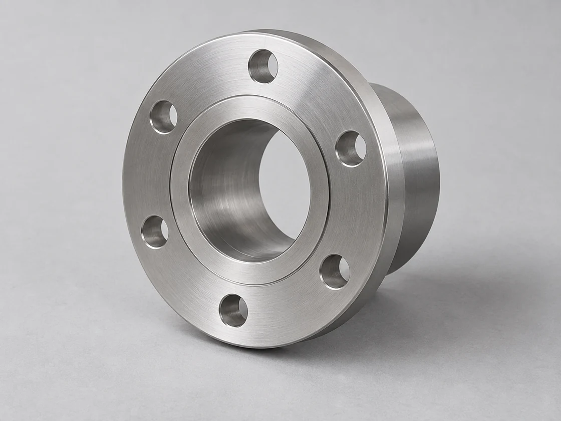
We machine flange adapters for different pilots and bolt patterns. A centered pilot locates the joint; bolt access and the space between the two faces determine whether it can actually be assembled.
Discuss this component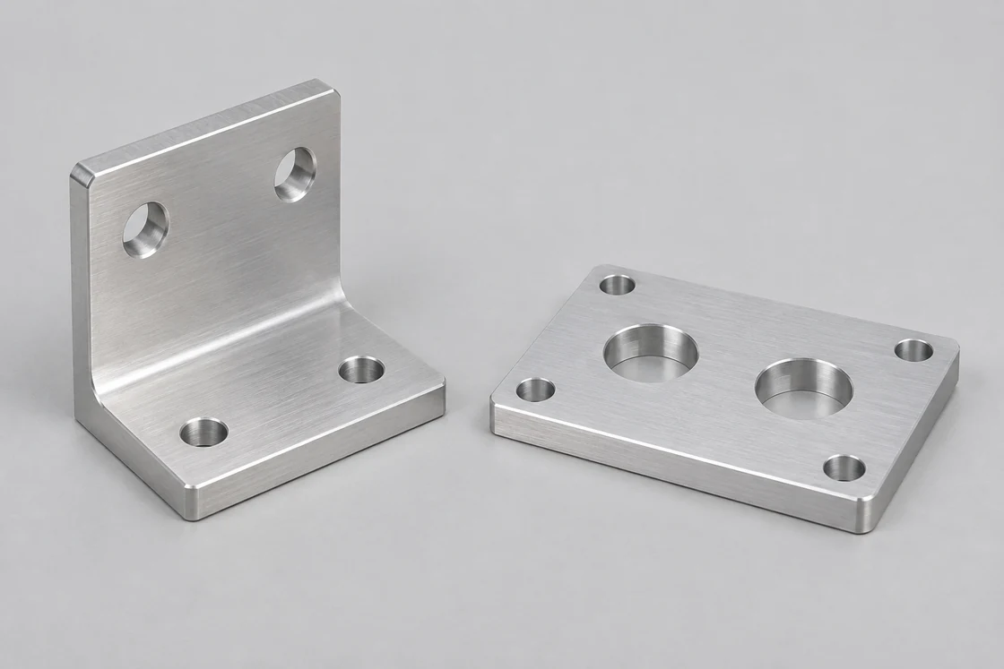
Mounting plates can provide a fixed locating pattern or slots for alignment adjustment. A plate that changes equipment height also changes the shaft centerline, so its thickness is part of the installation fit.
Discuss this component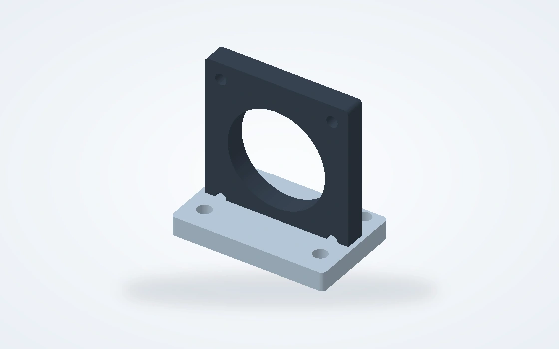
We machine sensor and cover brackets with room for the installed connector and removal tools. A sensor face that is correctly positioned but inaccessible after the guard is fitted still creates a maintenance problem.
Discuss this componentThe same replacement part can fit its fasteners yet fail at the rotating or exposed interface. These are the decisions that change the component geometry.
A worn seal track does not always require a new shaft. A replaceable sleeve is useful when the underlying shaft and its bearing seats remain serviceable and the seal arrangement accepts the sleeve geometry.
Wear at a bearing seat, a bent shaft or damaged drive features need a different repair decision. Copying the visible outside shape of a sleeve will not correct those faults.
The installed seal lip must run within the finished sleeve track. Sleeve length and shoulder position matter when a replacement seal puts the lip in a different axial location.
The sleeve and cover need a clear removal path past neighboring shoulders and housings. A replaceable component should not become trapped when the surrounding hardware is assembled.
An adapter can retain the existing equipment base while accommodating a new auxiliary unit. The design has to connect both mounting patterns without shifting the required shaft or sensor position.
On a belt-driven auxiliary, adjustment slots need travel in the tensioning direction. Fixed locating faces serve a different purpose: they establish the final operating position.
Plate thickness sets the mounted height. Slot length sets the available movement; neither can be chosen from the bolt diameter alone.
Two valid bolt patterns can still conflict inside one adapter. Recessed heads, assembly order or a thicker body may be needed to keep the second set of fasteners accessible.
For an aluminum mount on steel equipment, stainless fasteners do not remove the corrosion question. Moisture, contact between the metals and water trapped beneath the mount all affect the connection.
Isolation washers or spacers can interrupt metal contact. Where the connection also provides electrical bonding, that isolation must be coordinated with the equipment’s bonding design.
A recess beneath a horizontal mount can retain water against an otherwise protected surface. Joint geometry and drainage deserve attention alongside the exterior coating.
A coated mounting face and an exposed electrical contact have different jobs. Keeping their coverage separate avoids removing protection everywhere just to make one contact.
The trial needs to answer a specific question before the component moves into a repeat order.
For an assembly trial, check insertion, shoulder seating, fastener access and removal. An easier-to-machine trial material can answer a fit question, but it cannot establish wear or running performance.
For a running trial, use the intended material state, seal track and bearing fits. Otherwise a successful fit check can conceal the heat, wear or movement that appears in service.
For repeat supply, distinguish interchangeable service spares from paired assemblies. Selectively matched parts need to remain paired; they cannot silently become general replacements.
Material selection follows the contact surface and exposure. A corrosion-resistant exterior, a loaded shaft and a sliding bush rarely need the same material condition.
| Material | Component use | Where it fits / selection limit |
|---|---|---|
| Aluminum | Mounting plates; covers; auxiliary housings | Low mass; isolate wet dissimilar-metal joints |
| Carbon steel / alloy steel | Drive shafts; sleeves; mechanical adapters | Loaded seats; define final hardness and fit |
| Stainless steel / bronze | Stainless: wet mounts; bronze: sliding bushes | Select corrosion resistance or sliding behavior |
| Engineering plastics | Insulating spacers; non-load-bearing guide pads | Isolation; check temperature and sustained load |
The manufacturing route should keep the working axis and mounting references connected through the turned and milled features.
A split bearing housing needs a defined cap-and-base assembly for its finished bore. Replacing one half or mixing caps can change the seat geometry; the mating halves must stay identified through machining and inspection.
CNC milling servicesBearing seats and shoulders need to retain their relationship when keyways, flats or cross-holes are added. Burrs at those intersections can stop a hub seating even when the turned diameters are correct.
CNC turning servicesFor an adapter with angled mounting faces, locating each face from one common reference avoids a chain of unrelated setup dimensions. Tool access also determines the internal corner radius available beside a mounting boss.
5-axis machining optionsA part that passes an outside-diameter check can still bind, run off-axis or damage a seal. The following interfaces need separate controls.
A ring carrying a rotating load usually needs interference to resist creep. A bearing position designed to move axially may need a sliding seat. Using the same tight fit at both positions can prevent the intended thermal movement.
Clearance bolt holes allow installation movement; they do not precisely center an adapter. A pilot controls radial location, while the seating face controls tilt and axial position.
Seal-track texture and runout are independent of nominal diameter. A correctly sized track with a scratch, sharp entry edge or excessive movement can still damage the lip or lose sealing contact.
Added coating increases an outside diameter and reduces a bore. Final fit limits must apply after treatment, or the fitted areas need defined masking; an acceptable bare-metal measurement is insufficient.
Finish the working surface for its contact, and the exterior for its exposure. Applying one finish everywhere can change a fit or an electrical connection.
A seal passes over the shaft end, grooves and steps during installation. Smooth lead-ins and protected sharp features prevent damage before the lip reaches its running track.
Keep coating boundaries away from a sliding track where a raised edge would contact the seal or bush. For exposed mounts, coverage must extend into the recesses where moisture can remain.
Heat treatment can move a finished seat. Where close fits are required, the route needs allowance for the final machining operation after treatment, with hardness and fitted size accepted in that final condition.
The useful inspection result is tied to the component’s failure risk: a sleeve track, a bearing axis or an adapter face needs more than a general dimensional report.
Our quotation identifies which component measurements and material records accompany the order. Assembly balance, alignment and running acceptance are defined separately.
| Record or check | Installation risk | Useful evidence |
|---|---|---|
| Shaft and sleeve seats | Creep, binding or seal-track movement | Finished diameters + runout to shaft datum |
| Housing and adapter interfaces | Shaft offset or tilted adapter | Bore axis / pilot to mounting face |
| Processed surfaces | Fit lost after treatment | Post-process sizes + masked-area coverage |
| Material and part identity | Wrong shaft or sleeve condition | Specified grade/state tied to part identity |
| Seal-running surface | Lip wear or leakage | Specified texture + track edge condition |
We supply machined components, not a complete pump or generator rating. Pressure-boundary or other regulated parts require the applicable design, material, test and supplier qualifications to be established as part of that supply scope.
We plan protection around the finished interfaces and keep each component identifiable through receiving and installation.
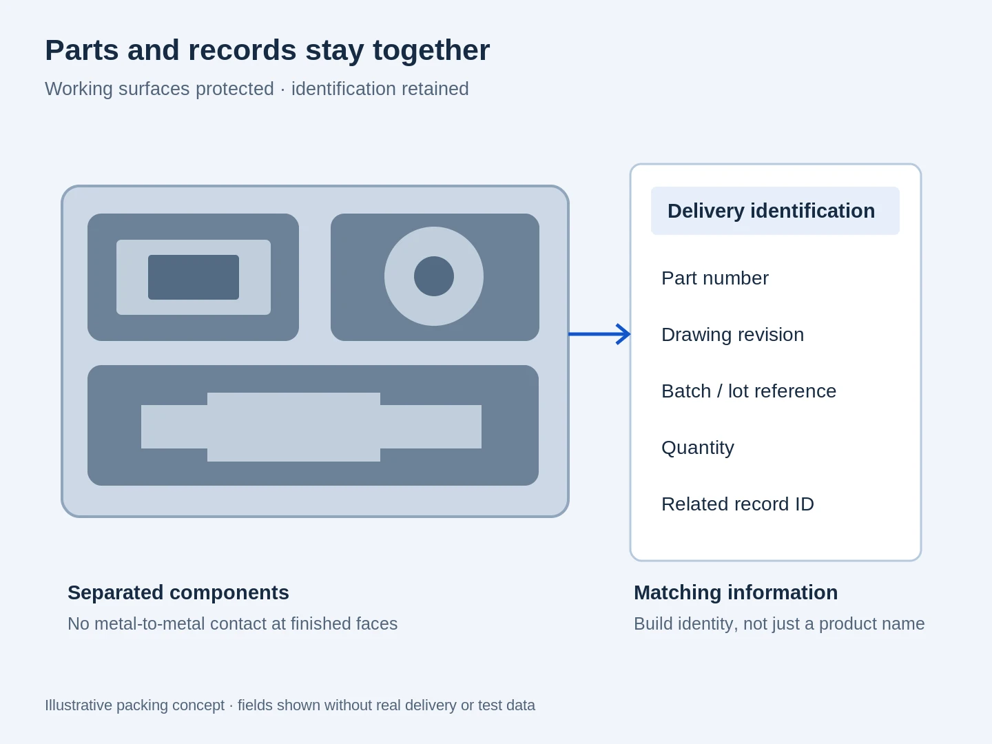
A sleeve track can be scored by an adjacent thread without visible damage to the carton. Separating these surfaces preserves the finish that was inspected before dispatch.
Where an order includes selectively matched shafts and sleeves, pairing marks must survive unpacking. Interchangeable service spares need part and revision identification instead of an assumed pairing.
A repaired shaft may require a different sleeve bore from a new shaft. A separate repair-size reference keeps that sleeve out of the stock intended for the original shaft size.
Use the seal or sleeve manufacturer’s standard product when its shaft range, running surface and installation method fit the application. Our custom machining offer suits a drawing-defined bore, shoulder, length or material that the standard product does not provide; it is not automatically interchangeable with a thin repair sleeve.
It can identify the layout, but a worn surface may be undersize, tapered or oval. Compare unworn areas and the mating shaft with the original drawing before releasing the new dimensions. We manufacture the agreed replacement definition rather than reproducing the wear.
No. Bearing arrangement, load direction, speed and temperature affect fit selection. The bearing designation and locating arrangement must be known before the shaft tolerance is chosen; selecting a commonly used fit code alone can produce the wrong clearance or mounting behavior.
Yes, an adapter can carry different interfaces on its two sides. Keep each side’s units and thread standard explicit. Similar nominal thread diameters do not make the threads interchangeable, and converting a shaft size does not establish its mating fit.
We can review a casting or partly machined housing for the remaining work. The key is whether enough stock remains around the required bore and mounting faces to put them in the correct relationship. A pre-existing off-center bore may leave insufficient material even when the outside dimensions are adequate.
It may. Runout controls geometric movement around a reference axis; balance concerns the rotating mass distribution. Couplings, keys and other installed parts change that distribution, so the balance requirement needs to identify the rotating configuration and acceptance method.
Only if the sleeve surface is the cause. Misalignment, bearing movement, contamination or an unsuitable seal can damage a new track as well. Establish the failure cause before changing the sleeve material or dimensions; we can then quote the component change that addresses it.
Close tolerances are most useful at bearing seats, seal tracks and coupling fits. Clearance sections can usually retain wider drawing limits. Separating those functions avoids paying for finishing and inspection that do not improve the installed fit.
Engineering references for pump interfaces and outdoor metal connections.
Send the part drawing, mating shaft or bearing details, material and quantity. We will quote the component machining and the finished-interface checks needed for your order.
Component drawing, mating references and its role in the equipment.
Quantity and whether the parts are for assembly checks, running tests or repeat supply.
Material, finish, requested records and target delivery date.
An initial model or part description can start the review.