Skip to content
VETCNCCNC MANUFACTURING
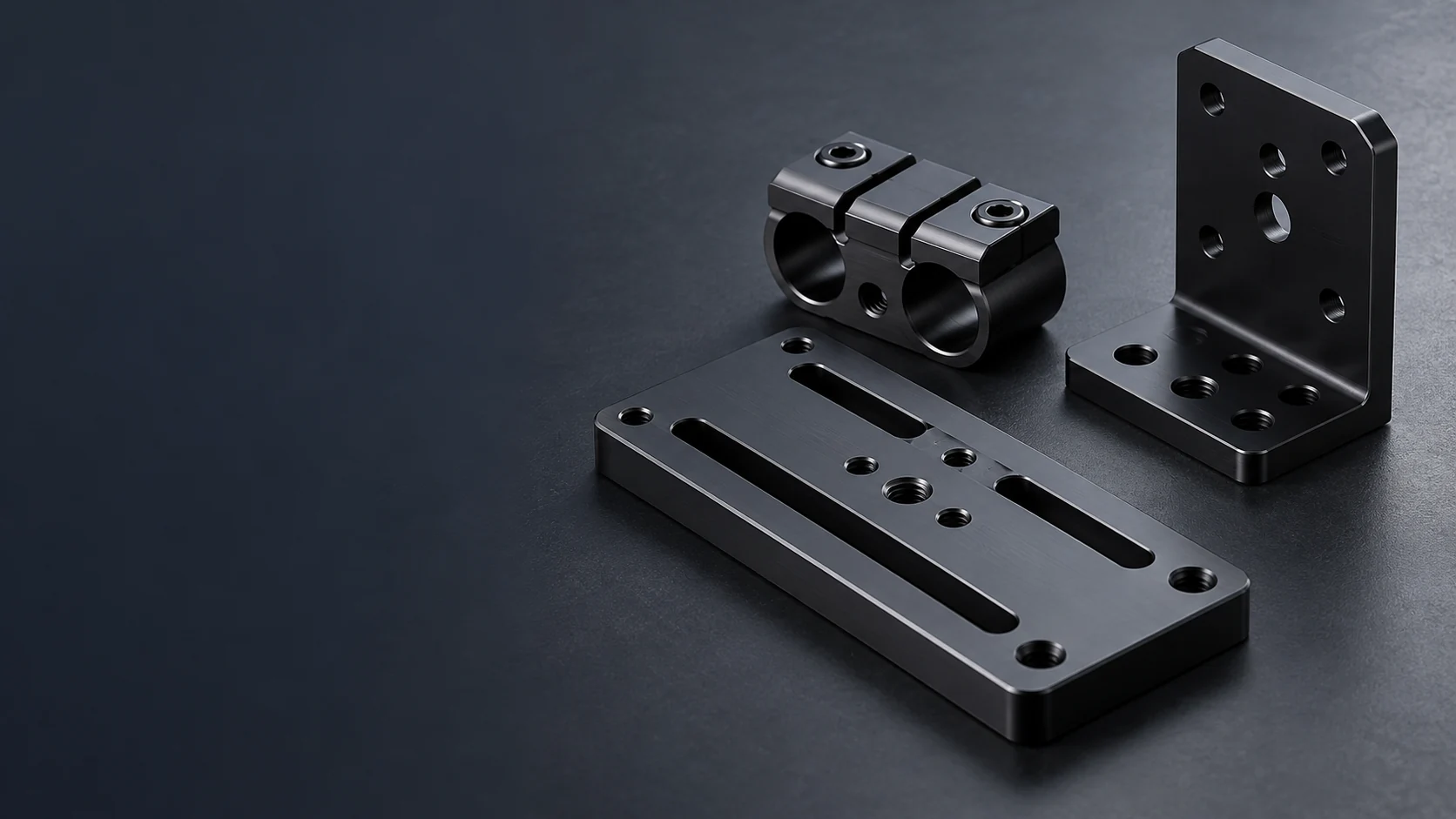
Black machined camera baseplate, twin-bore rod clamp and accessory bracket on a dark work surface

CNC Machining for Film and TV Equipment

We machine camera baseplates, cage components, rod clamps and lens supports for cinema and broadcast equipment developers. Your camera and accessory interfaces define the part geometry, from screw and locating-pin patterns to rod spacing and access around the assembled rig.

  • Camera mounting parts
  • Lens and rod supports
  • Accessory adapters

Custom components for camera rigs and accessories

We supply individual machined parts for your equipment design. The families below cover camera support and accessory interfaces, rather than retail camera kits, scenery or film props.

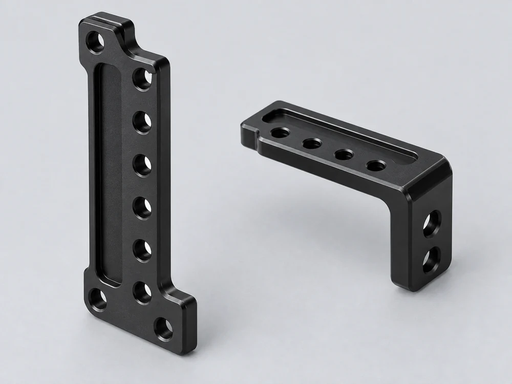
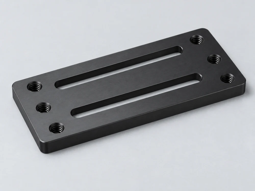
Black anodized camera baseplate with two parallel slots and six mounting holes

Camera baseplates and risers

Baseplates and riser blocks establish the camera’s seating position above the support system. We machine mounting slots, screw seats and locating features around the camera underside and the selected receiver.

  • Camera seats
  • Screw slots
  • Riser heights
Discuss this component
Black camera cage side plate and separate top plate with mounting holes and a relieved pocket

Cage side and top plates

Top plates, side plates and connecting rails create accessory positions around a camera body. Openings preserve access to controls, battery doors and card slots; local mounting pads carry the defined threaded and locating interfaces.

  • Accessory patterns
  • Body clearance
  • Control access
Discuss this component
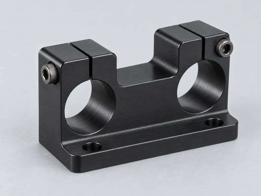
Black twin-bore rod clamp with split clamping sections and a two-hole mounting flange

Rod clamp blocks

Single and dual-rod blocks connect supports and accessories to the chosen rod system. Bore diameter, center spacing and clamp split geometry are controlled together so the part can position the rods and perform its intended clamping action.

  • Rod bores
  • Center spacing
  • Clamp splits
Discuss this component
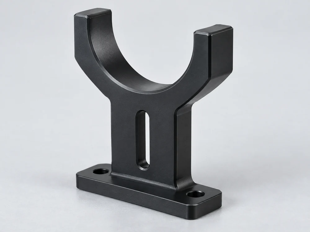
Black U-shaped mechanical lens support bracket with a slotted upright and two base mounting holes

Lens support brackets

Support posts, bridges and cradles position the lens support foot or contact pad above the rods. We machine the height adjustment, mounting slot and support seat to the lens and camera arrangement supplied by the equipment developer.

  • Support height
  • Foot interfaces
  • Contact-pad seats
Discuss this component
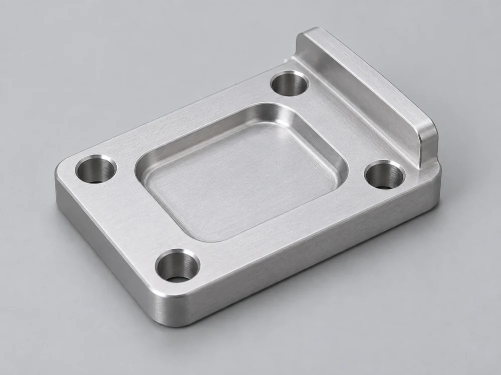
Machined accessory mounting plate with a shallow pocket and four round mounting holes

Monitor and receiver adapters

Adapters provide a defined attachment for monitors, wireless receivers and other on-camera devices. Their offsets leave room for cable connectors and keep locating pins clear of adjacent screws and equipment surfaces.

  • Device interfaces
  • Anti-rotation features
  • Connector space
Discuss this component
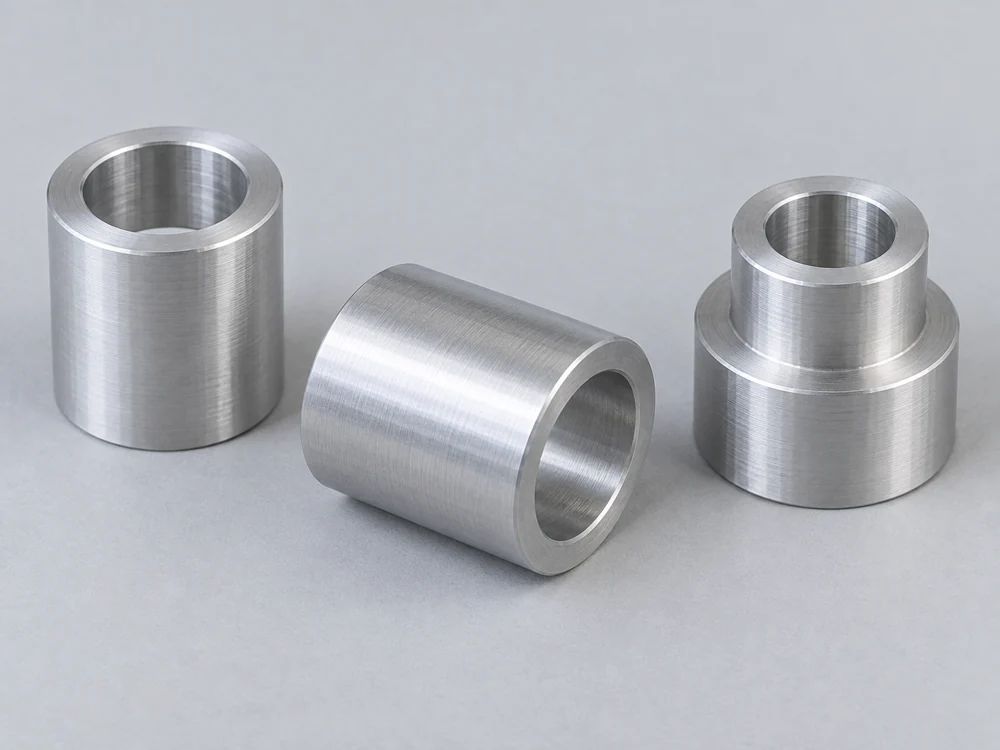
Three silver stand-off spacers with through-bores, including one stepped sleeve

Threaded bushings and spacers

Turned reducers, threaded bushings and stand-offs connect mounting sizes or establish a seating distance. Shoulder position, thread form and usable engagement are defined separately from the visible outside length.

  • Thread reducers
  • Seating shoulders
  • Stand-off lengths
Discuss this component

Camera builds, lens support and onboard accessories

The useful machining definition comes from the assembled rig. A baseplate sets camera position, a lens support follows the optical-axis geometry, and an accessory adapter must leave the device usable once mounted.

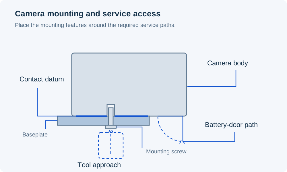
Side view of a camera body on a baseplate showing the contact datum, mounting screw tool approach and an unobstructed battery-door opening

Developing a camera cage or baseplate

We machine the camera-contact features from the designated body or interface drawing. The underside screw position and local seating surfaces establish the baseplate; accessory holes then relate to that location.

A cage opening has to clear the moving control or door, not merely its closed outline. Articulated displays, battery removal and card access belong in the model used to release the surrounding plates.

Mounting reference

Camera-contact faces and any locating features determine where the accessory pattern sits relative to the body.

Working access

Fastener heads, release catches and tool paths remain accessible after the cage is assembled.

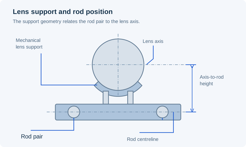
Front view of a mechanical lens support and two rods held in a clamp, showing the lens axis, rod centreline and their vertical relationship

Keeping rod-mounted accessories on the lens axis

The selected rod system defines both rod spacing and its relationship to the optical axis. A riser changes the camera height; a lens support then needs the correct seat or adjustment range for that resulting arrangement.

We machine the support geometry to the specified contact point. A support should meet the intended lens foot or pad without forcing the lens into position by tightening the mounting screw.

Rod-system geometry

Rod diameter alone does not identify the system. Center spacing and optical-axis height are part of the same interface definition.

Lens contact

The support contact is kept clear of moving focus or zoom rings and located at the point defined by the lens-support design.

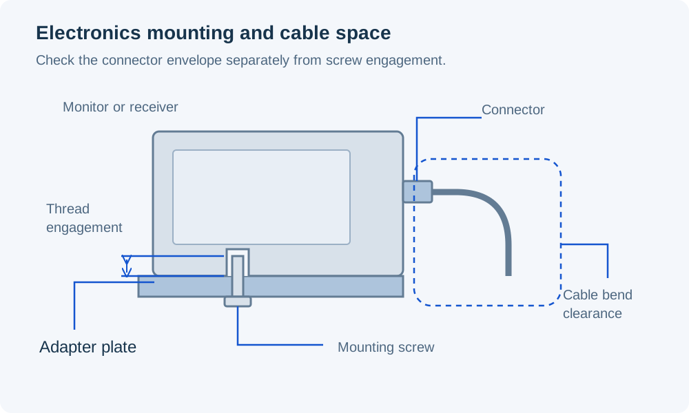
Monitor or receiver on an adapter plate, with a connector and cable-bend envelope separated from the mounting screw engagement

Mounting monitors, receivers and control devices

We machine adapters around the device mounting interface and the space occupied by the connected cables. A right-angle connector, locking collar or release button may need more room than the device body itself.

Mounting plates also preserve the selected device’s ventilation openings and removal path. The equipment layout identifies those zones before pockets and lightening openings are added to the adapter.

Connector envelope

The cable plug and the space needed to connect or release it form part of the clearance model.

Device replacement

An offset or access opening can allow removal of the device without first dismantling the surrounding cage.

Interface prototypes, finished samples and repeat parts

We separate the sample used to check rig geometry from the finished component used to approve fit and appearance.

Camera-interface prototype

The first part checks seating on the nominated camera, access to its controls and the location of the attached accessory. Model variants are checked against their own interface geometry.

Finished fit-check set

The intended surface treatment is included when checking rod clamps, fitted pins and threaded interfaces. The equipment team evaluates the assembly with its actual mating parts.

Repeat accessory components

Approved mounting geometry and finish remain tied to the part revision. A new camera body, rod system or receiver profile is treated as a changed interface where its dimensions differ.

Material parameters for plates, clamps and contact parts

Aluminum grades differ in strength while both keep part mass below that of comparable steel geometry. Stainless details and polymer contact pads serve different functions; we retain their specified grade and condition rather than substitute on appearance.

CNC Machining for Film and TV Equipment — material parameters
Material / conditionReference parametersComponent use
6061-T6 / T6511 extrusionYield ≥240 MPa; density ≈2.71 g/cm³Baseplates, risers and accessory mounts
7075-T651 · Kaiser referenceTypical yield 503 MPa; tensile 572 MPaDrawing-specified high-strength aluminum details
316L / EN 1.4404Elastic modulus 200 GPa at 20°CSpecified stainless bushings and mounting details
POM-C · TECAFORM AH naturalTensile modulus 2.8 GPa; water uptake 0.05%Replaceable lens-contact pads and locating details

References: Hydro Alloy 6061 extrusion minimum yield and typical density; Kaiser 7075 sheet/coil/plate typical T651 properties; Outokumpu Supra 316L/4404 physical data; Ensinger TECAFORM AH natural (modulus at 1 mm/min; water uptake after 24 h at 23°C). Typical material values are not finished-rig load ratings.

Machining plates, clamps and threaded details

We plan the working interfaces before removing material for pockets and lightening features. The final checks relate those interfaces to the mounting face or rod centerline used in the rig.

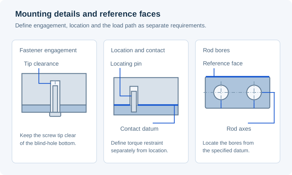
Camera seats, rod centers and locating pins

We concentrate dimensional control on the surfaces that locate the equipment. Clearance pockets and external contours can then follow the space available around those references.

Three details show a screw clear of a blind-hole bottom, a locating pin and contact datum, and paired rod bores located from a reference face

Camera seating faces

The contact pads establish the baseplate position. Reliefs clear the camera underside so an unintended high point does not prevent the specified pads from seating.

Rod bores and clamp geometry

Parallel rod bores share the required center spacing. Clamp slots and screw positions follow the designed closure, with acceptance tied to the final bore condition and the intended mating rods.

Anti-rotation pin patterns

A mounting thread holds the attachment while the specified pins establish its rotational location. Pin diameter, pattern and protrusion need the matching receiver geometry; the screw size alone does not define it.

Screw projection and usable depth

The screw must clamp the mounting stack without bottoming in the mating hole. Plate thickness, counterbore depth and any washer or captive feature determine how much thread projects beyond the seating face.

Finishing camera-facing and working surfaces

The finish specification distinguishes visible exterior areas from rod bores, pin fits and threaded connections.

Exterior texture and handling edges

Visible machining texture and edge breaks are defined for the exposed faces. A broad exterior edge can be eased without rounding a locating feature or reducing the designed clamp contact.

Anodizing around fitted features

Where anodizing is specified, the allowance and masking plan account for its dimensional effect on rod bores, locating holes and threads. Finished interface checks use the coating condition required by the drawing.

Replaceable lens-contact pads

A separately defined polymer pad can provide the chosen contact surface between a machined support and the lens. Its material, thickness and contact shape remain part of the support design rather than an unspecified soft layer.

Thread, pin and rod-system reference dimensions

These selected interface dimensions help define camera accessory parts. We use the complete mating-interface drawing for tolerances, depths and acceptance; a nominal dimension is not a blanket compatibility claim.

Thread checks establish the specified fit and usable depth. Pattern and rod-location measurements establish where the accessory sits relative to its mounting references.

CNC Machining for Film and TV Equipment — feature specifications
Selected interfaceReference dimensionsInspection focus
1/4-20 UNC mounting threadNominal Ø6.35 mm; pitch 1.27 mmSpecified thread class and usable depth
3/8-16 UNC mounting threadNominal Ø9.525 mm; pitch 1.5875 mmSpecified thread class and usable depth
ARRI 1/4-inch Pin-LockLocating circle Ø10.4 mm; nominal pins Ø3 mmFull selected pin/hole geometry and mounting datum
ARRI 3/8-inch Pin-LockLocating circle Ø15 mm; nominal pins Ø3 mmFull selected pin/hole geometry and mounting datum
15 mm LWS rod systemRod Ø15 mm; centers 60 mm; optical-axis height 85 mmBore spacing and centerline relative to camera position

Interface references: ARRI Pin-Lock, version 2023-05; OConnor Labs, Rod Standards. Inch thread values use 25.4 mm/in and pitch = 25.4/TPI. Optical-axis height is measured above the rod centerline. These selected nominal dimensions do not replace the full mating drawing, including pin/hole limits, depths and final finishing allowances.

Component inspection and rig validation

Our quotation defines the machined-part inspection. Payload ratings, suspended-equipment safety, gimbal performance and optical calibration require the equipment developer’s separate validation; they are not established by matching an interface dimension.

Identification for assembly and repeat supply

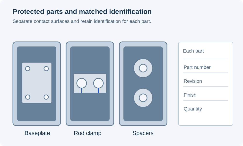
Thread adapters and spacer variants can look alike while fitting different parts of the rig. Their component references remain distinct through delivery.

Baseplate, rod clamp and spacers in separate protective compartments beside identification fields for part, revision, finish and quantity

Mounting-size identification

Packaging identifies the ordered thread and rod-system variant. A 1/4-20 bushing is not mixed with a visually similar metric-thread component.

Camera and accessory revisions

Baseplates, cage plates and receiver adapters retain their part and revision references. A changed camera underside or receiver profile is not supplied under an unchanged geometry record.

Contact surfaces protected

Separate packing protects camera seating pads, rod bores and visible faces from neighboring metal parts. Small spacers and bushings remain identifiable within the shipment.

Film and TV equipment machining FAQs

Are 15 mm LWS and 15 mm Studio rod mounts interchangeable?

No. Both use 15 mm rods, but LWS uses 60 mm center spacing and an 85 mm optical-axis height. The Studio arrangement uses a different spacing, height and lateral offset. Specify the complete rod system before defining a baseplate or lens-support bridge.

Does a 3/8-to-1/4 thread reducer preserve an anti-rotation interface?

Not by itself. A reducer changes the available thread; it does not reproduce the surrounding locating-pin pattern. The ARRI 1/4-inch and 3/8-inch Pin-Lock interfaces use different locating circles. An adapter intended to preserve rotational location needs the complete selected interface on each side.

Can a quick-release plate be made from the receiver name alone?

Use the receiver profile or an approved mating drawing. The width label alone does not define the flank geometry, seating depth, clamp travel or any retention feature. We machine the released plate profile; the equipment team confirms engagement with the nominated receiver.

Can you size a lens support from the focal length or filter thread?

Those values do not define the support contact. We need the lens foot interface or the approved barrel-contact location, together with its height above the selected rods. The contact must also clear the moving focus and zoom features of that lens configuration.

Does black anodizing guarantee a low-reflection camera part?

No. Color alone does not define how a surface reflects light. Alloy, surface preparation and final texture affect the appearance. For a surface near the optical path, specify the required finish and an acceptance sample or relevant reflection criterion instead of ordering only “black anodized.”

Does the finished part’s weight establish compatibility with a gimbal?

Weight is only one input. The installed camera, lens, cables and accessories also determine the balance position and clearance through movement. We can manufacture the mounting component to its released geometry, but gimbal compatibility and operating performance must be checked on the complete intended rig.

Can an M6 fastener be used in a 1/4-20 camera mounting thread?

No. A 1/4-20 UNC thread has a nominal diameter of 6.35 mm and a pitch of 1.27 mm. A coarse M6 thread is 6 mm with a 1.0 mm pitch. The similar appearance does not make them interchangeable; identify the thread on both sides of any bushing or adapter.

PROJECT SUPPORT

Discuss your camera equipment component

Share the part drawing, material and quantity, together with the camera, rod or accessory interface that controls its fit.

VETCNCCNC MANUFACTURING
English
Email us

Tell us about your project

Share your requirements and we will get back to you by email.

PDF, CAD or ZIP · up to 20 MB