Skip to content
VETCNCCNC MANUFACTURING
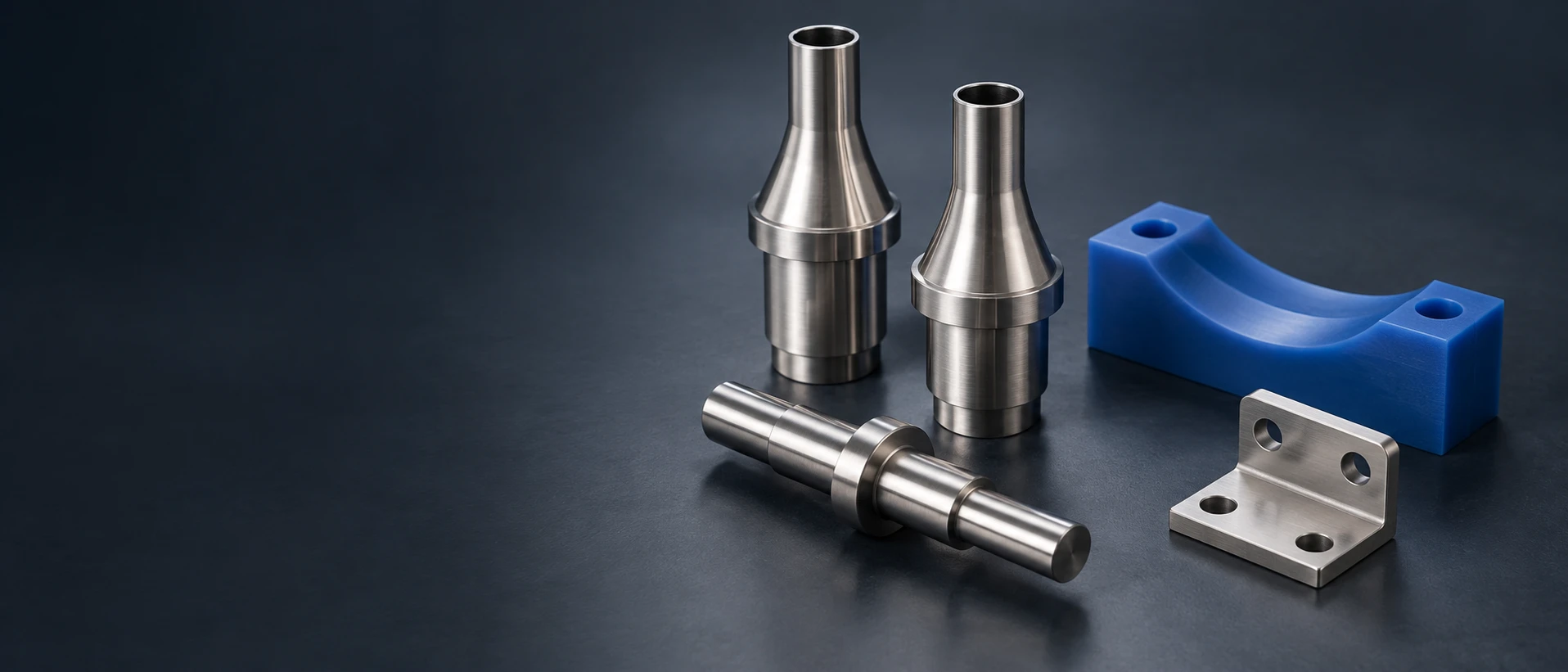
Stainless filling nozzles, shaft, mounting bracket and blue polymer guide

CNC Machining for Food Equipment

Custom stainless steel and engineering-plastic parts for filling, product handling and packaging equipment. We machine nozzles, shafts, guides, mounts and tooling to your drawing, with the specified interfaces and final surface condition.

  • Drawing-defined components
  • Metal and polymer parts
  • Prototype and repeat orders

Food equipment components

We supply individual machined components for equipment builders and engineering teams. A project can combine turned flow-path details, milled mounts and replaceable polymer tooling. The drawing identifies where a component contacts product, encounters cleaning fluids or serves a mechanical support function.

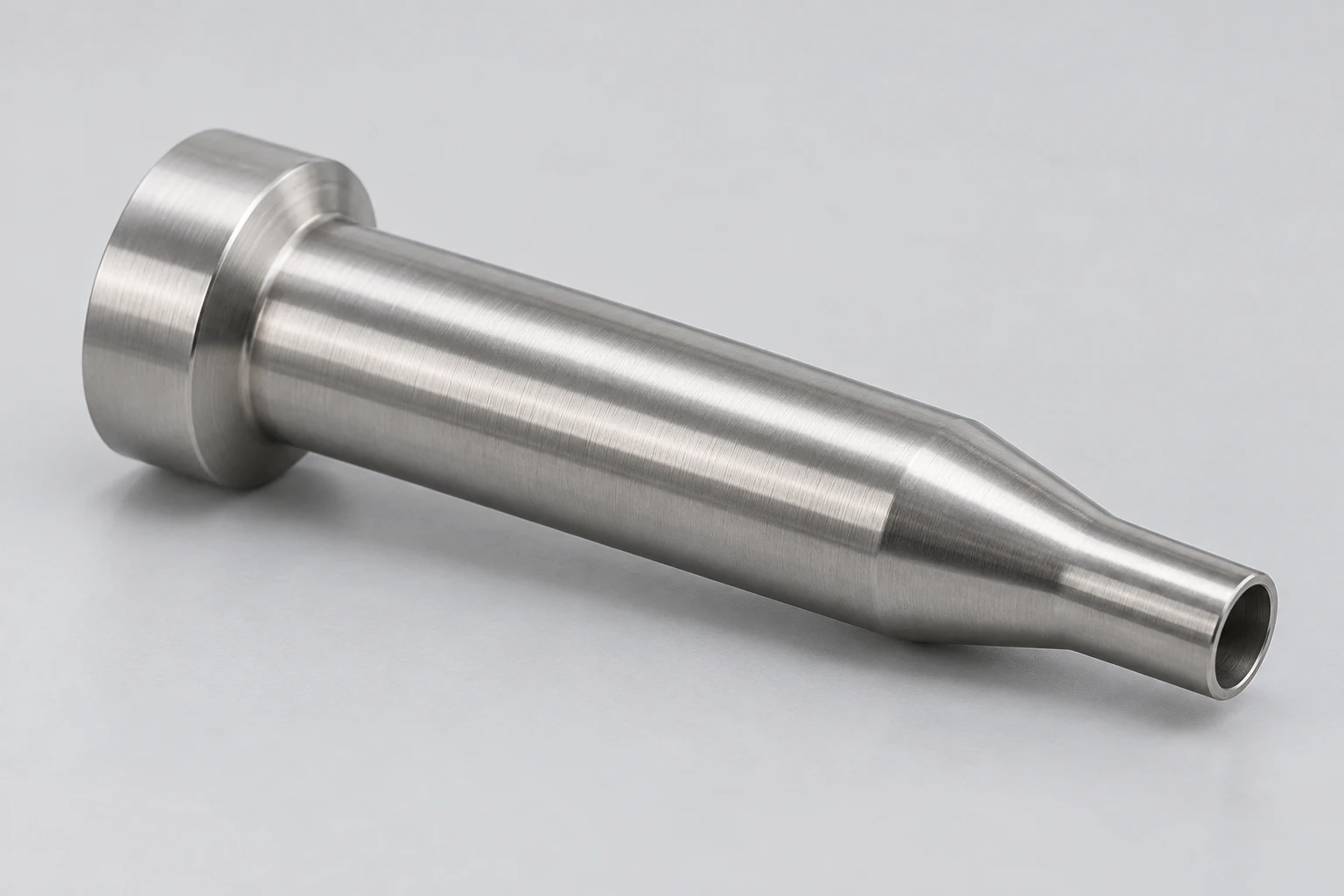
Stainless filling nozzle with an open bore and seating shoulder

Filling nozzles and tips

Bores, outlet profiles and seating shoulders define a custom filling nozzle. The internal path needs machining and finishing access; the external mounting diameter locates the nozzle without changing the specified flow opening.

  • Open bores
  • Outlet profiles
  • Seating shoulders
Discuss this component
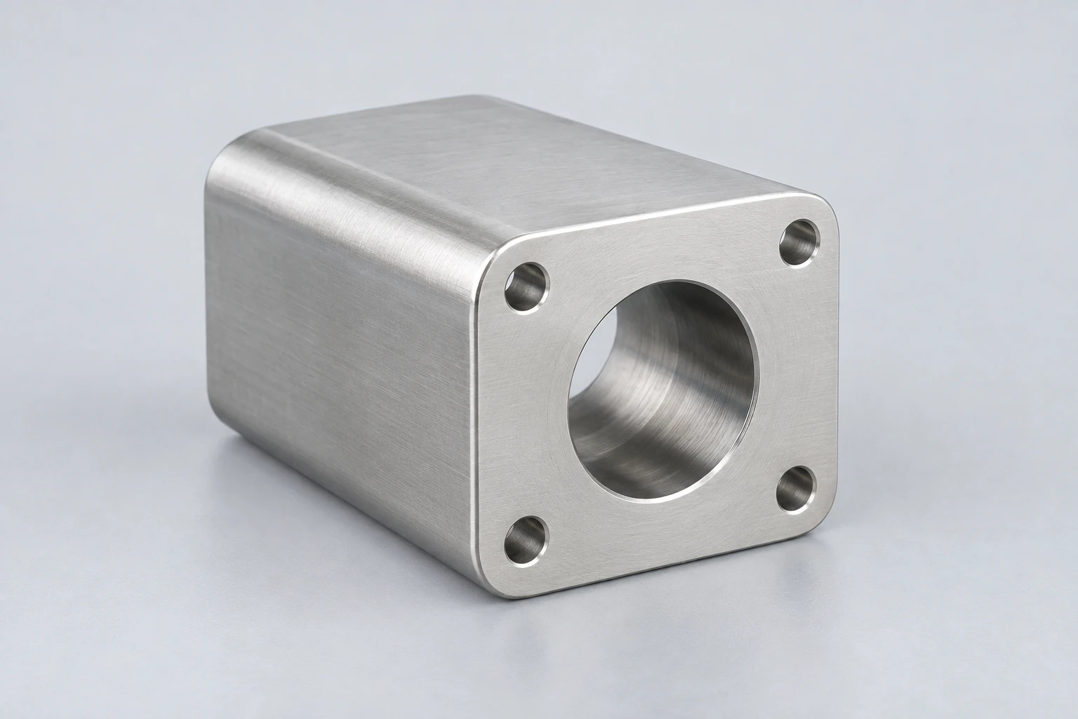
Stainless flow body with a central passage and mounting holes

Flow bodies and valve details

Machined bodies, covers and seat carriers for a specified assembly. Port intersections, sealing lands and mounting patterns are kept distinct, so a mounting hole or recess does not unintentionally open into the product path.

  • Port intersections
  • Sealing lands
  • Mounting patterns
Discuss this component
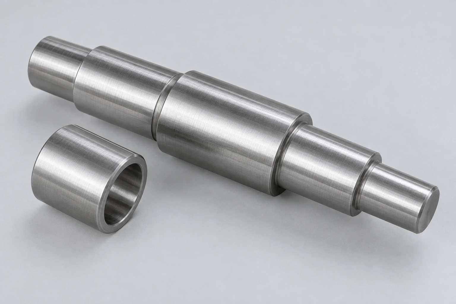
Stepped stainless shaft and separate sleeve

Shafts, sleeves and spacers

Stepped shafts and sleeves connect rollers, bearings and drive components. Bearing seats, axial shoulders and retention features establish the working position; surfaces exposed to cleaning need their own material and finish definition.

  • Bearing seats
  • Axial shoulders
  • Retention features
Discuss this component
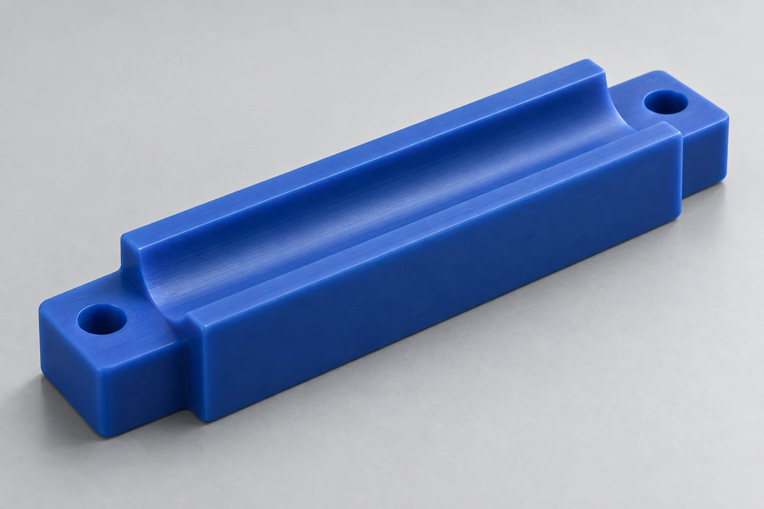
Blue polymer guide with a curved contact profile

Polymer guides and wear parts

Guide blocks, sliding strips and bushings made in the specified polymer grade. Contact profile, clearance and fastening geometry control how the part guides a container or supports a moving component as it wears.

  • Guide profiles
  • Running clearances
  • Replaceable inserts
Discuss this component
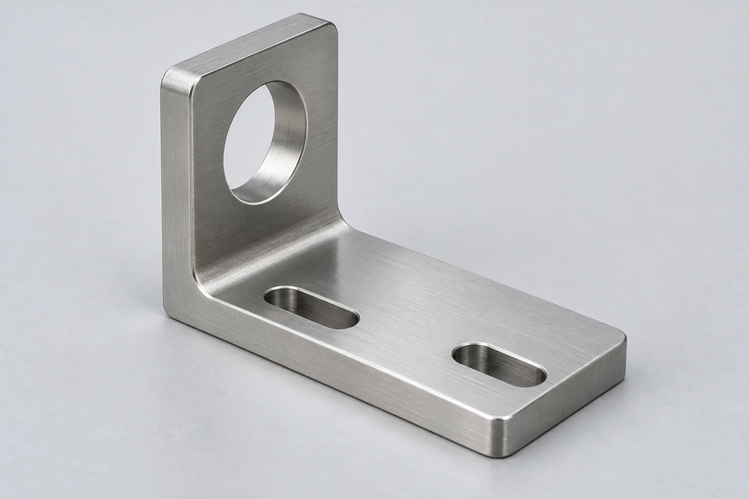
Stainless sensor bracket with an adjustment slot and locating bore

Sensor and equipment mounts

Brackets, support blocks and interface plates carry sensors or small mechanisms on the machine. Their mounting pattern and cable or tool access must fit the available space around guards, supports and neighboring components.

  • Mounting slots
  • Locating features
  • Service access
Discuss this component
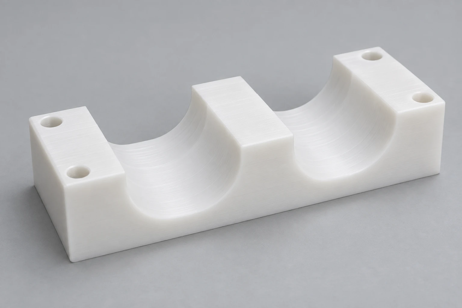
White polymer changeover nest with open container profiles

Changeover nests and tooling

Product nests, locating plates and removable tooling details for packaging and assembly stations. Each format can use its own contact profile while retaining the machine-side locating and fastening interfaces.

  • Format-specific profiles
  • Common mounting points
  • Removable tooling
Discuss this component

Filling, handling and packaging applications

The same production line contains parts with very different exposure. We separate product-path components from guides and supporting hardware, so the manufacturing definition reflects the surfaces that actually matter.

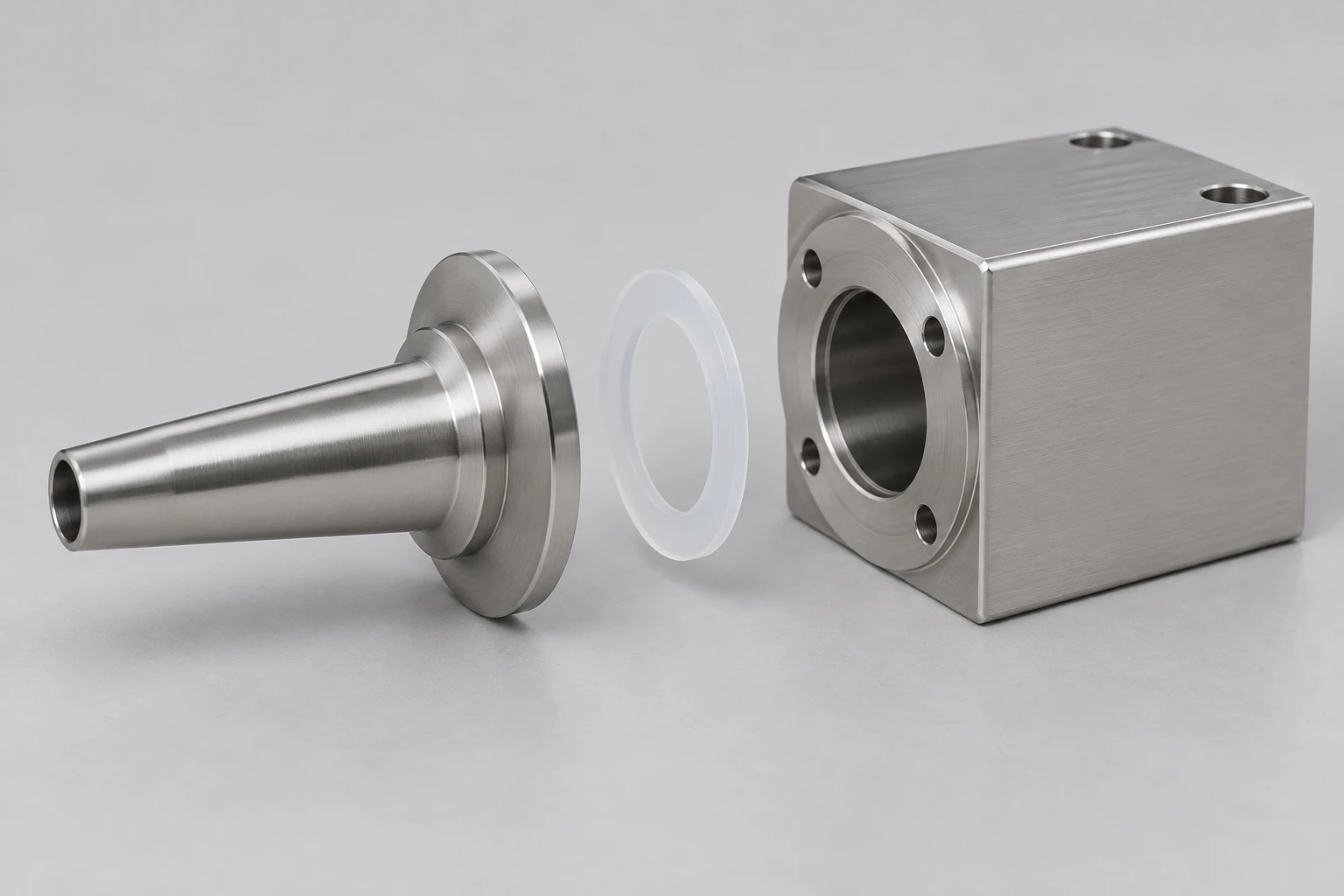
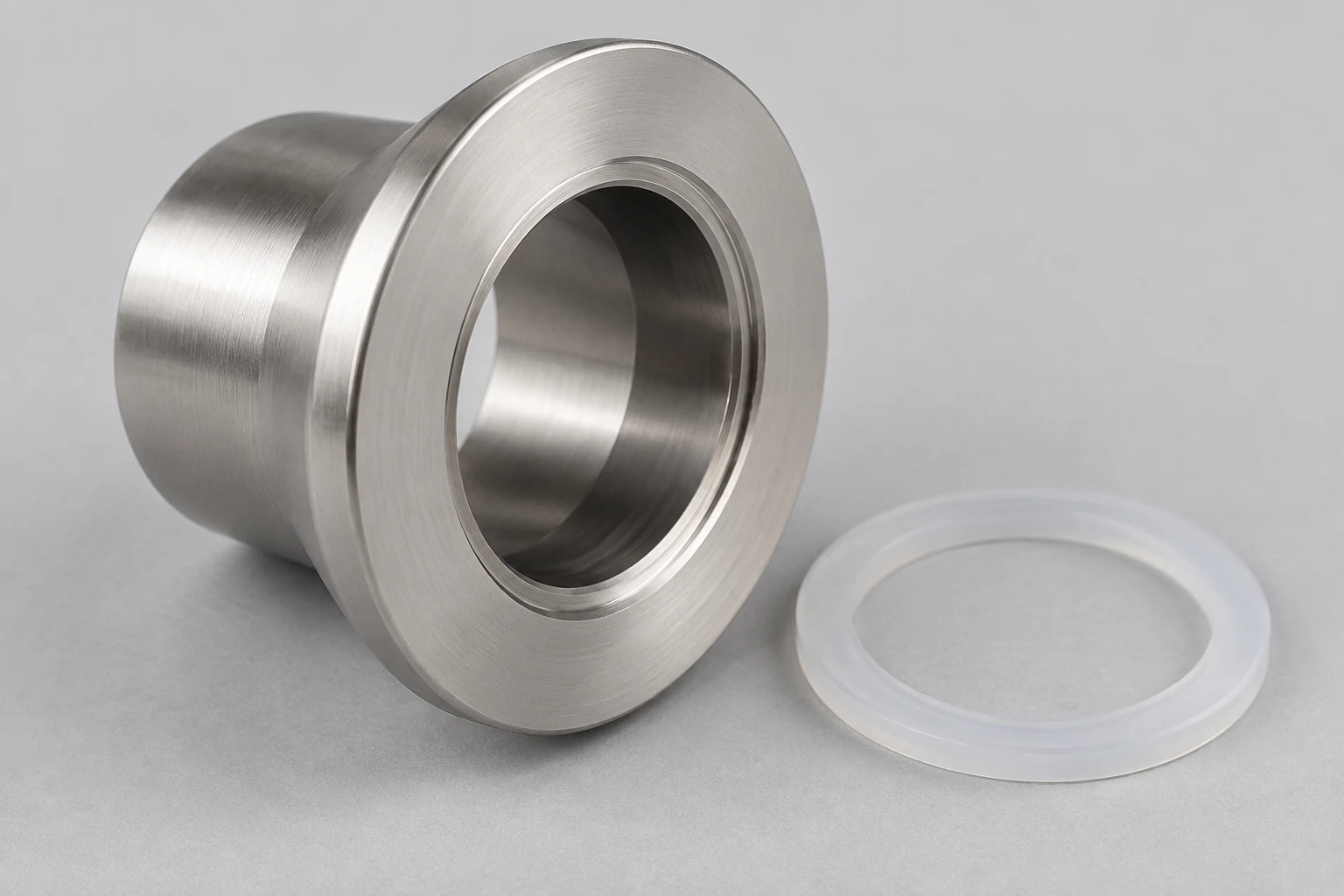
Separate stainless nozzle, flow body and annular gasket

Components in a liquid product path

Filling nozzles, seat carriers and flow-body details bring a wetted passage together with external locating and fastening surfaces. Their drawing needs to distinguish the internal path, its transitions and the surfaces that seal against adjoining parts.

A straight accessible passage and a blind intersecting passage present different cleaning and finishing problems. The equipment design determines drainage and cleaning access in the installed orientation; machining follows that geometry rather than assuming an external polish reaches inside. [1]

Product-side interfaces

Gasket seating, passage alignment and the assembled joint determine whether the transition leaves an exposed recess or gap.

External attachment

The clamping or mounting arrangement should preserve the product-side geometry without putting an unintended thread or fastener cavity in the wetted path.

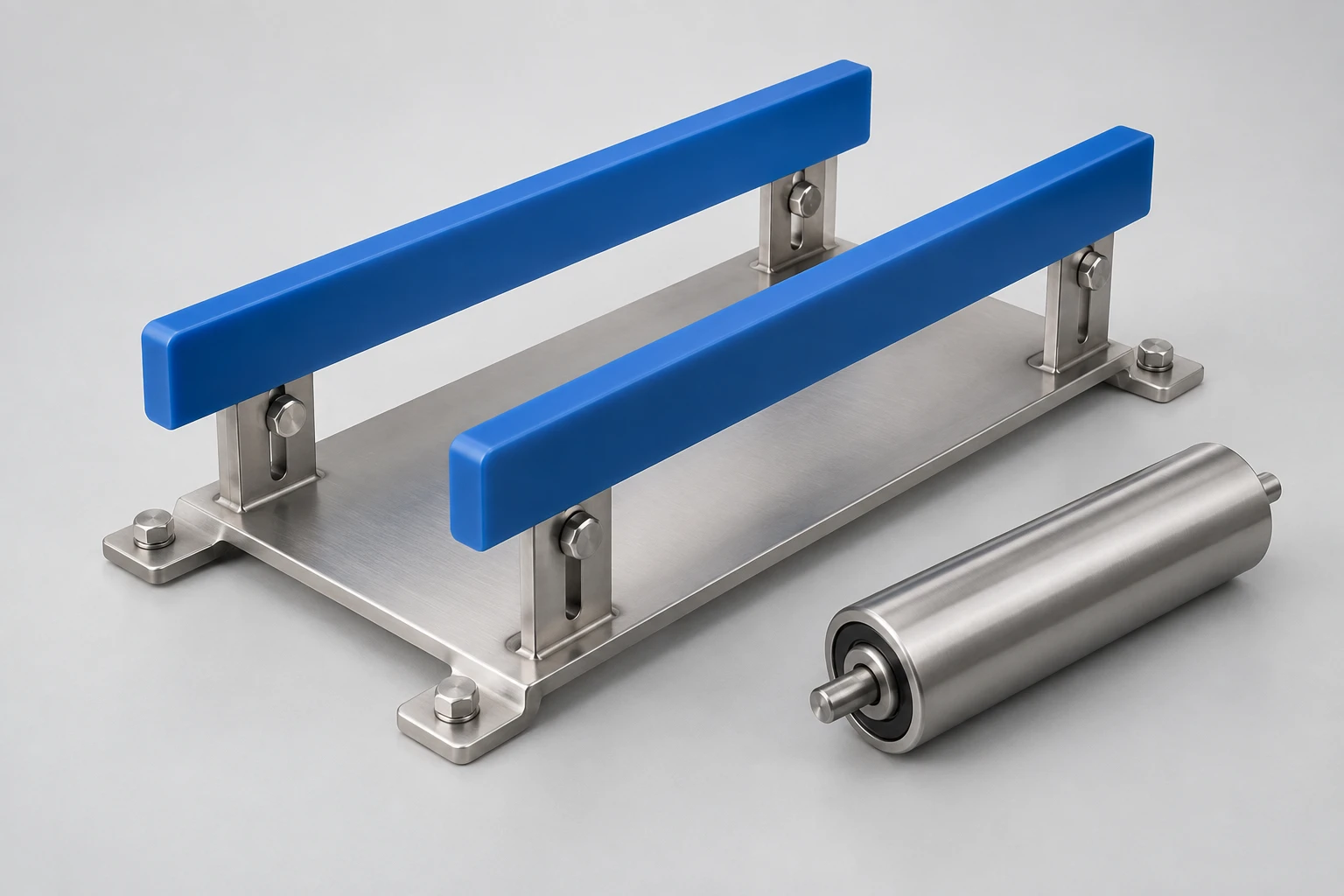
Blue polymer guides on a support plate beside a stainless roller

Guides and rotating details for product handling

Polymer guides, sleeves and turned shaft details control clearance, support and movement. A guide that touches a filled container has a different duty from a part in direct contact with unpackaged food.

Wear, cleaning chemicals and temperature act together. A replaceable guide needs sufficient running clearance in service as well as a defined cold inspection condition; the nominal material name alone does not describe those conditions.

Contact profile and clearance

Guide curvature and spacing follow the product or container format, with clearance for movement rather than a tight static fit.

Wear-part replacement

A separate wear insert can retain the machine-side mount while renewing the contact profile. Its part number and grade distinguish it from a visually similar alternative.

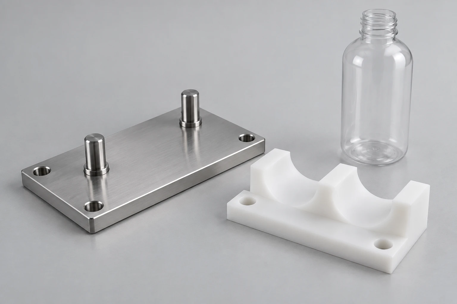
Locating plate, removable polymer nest and empty container

Format tooling for filling and packaging stations

Changeover nests, locating blocks and mounting plates place a container or package at a repeatable machine position. The working profile changes with the format, while the locating references can remain common to the station.

Tooling must allow loading, removal and access around the part. A split nest can expose surfaces that a one-piece enclosed pocket would leave difficult to machine or inspect.

Machine-side location

Locating faces, pins and mounting holes relate the replaceable tooling to the station datum.

Format-side geometry

Pocket profiles support the intended container surfaces, with clearance for loading and removal. Machine-side locating features hold the nest position independently of that clearance.

From fit checks to repeat parts

We distinguish a geometry trial from a component released for service. Material, surface condition and acceptance records become part of the build definition before the parts enter the equipment.

Fit-check components

Early parts can check nozzle reach, mounting access, guide spacing or a changeover profile. A dimensional fit trial does not establish how a different material or unfinished surface will behave during production cleaning.

First functional set

The first service-intended set brings the selected grade, finished geometry and specified surface condition together. The equipment team can then evaluate the component in the actual assembly and cleaning process.

Repeat and replacement orders

Repeat parts follow the accepted drawing revision and final condition. A material substitution, revised contact profile or changed cleaning regime needs a defined engineering change rather than an unrecorded replacement.

Material stiffness and thermal expansion

Polymer guides expand more and deflect more under load than stainless parts. We use the specified grade and working temperature when checking the drawing’s clearances; corrosion and cleaning chemistry also affect the choice between 304 and 316L.

Material stiffness and thermal expansion
Material / reference gradeElastic modulus (GPa)Linear expansion (µm/(m·K))
304 / EN 1.430120016
316L / EN 1.440420016
POM-C · TECAFORM AH natural2.8130
UHMWPE · Ensinger Polyethylene 10000.68180

Stock-material comparison values. Outokumpu Core/Supra: modulus at 20°C, expansion over 20–100°C. Ensinger TECAFORM AH natural / Polyethylene 1000: tensile modulus, longitudinal expansion over 23–60°C. These values do not establish cleaning-temperature or food-contact approval.

Machining the component geometry

Our milling and turning work covers the drawing-defined part. Machining access, connected features and finishing allowance determine how that geometry can be produced and checked.

Working surfaces and assembly interfaces

The most useful specifications identify which surfaces carry product, seal, locate or move. Those functions determine the relevant geometry and finish without applying one tight tolerance to every face.

Stainless adapter with an open bore, flat sealing land and separate gasket

Accessible passages and transitions

Bore entrances, cross-hole intersections and internal transitions need defined edge treatment and practical tool access. Installed orientation also affects whether liquid can drain; that relationship belongs in the equipment design. [1]

Sealing lands and gasket seats

Seat width, groove depth and mating-face alignment affect how the specified seal is supported. Finishing must preserve these dimensions rather than rounding a sealing edge into the adjacent surface.

Shaft seats and running clearance

A shaft diameter, its mating bore and their surface condition work together. The fit must account for the selected material and operating temperature, with inspection references that match the installed locating arrangement.

Repeatable removable interfaces

A locating face or pin establishes position; a slot allows adjustment. Distinguishing these roles helps a replacement guide or nozzle holder return to the intended position after removal.

Finishing and surface condition

The finish definition separates product-contact areas, sealing features and external hardware. We include the specified secondary processing in the component scope, with dimensions assessed in their required final condition.

Deburring and specified texture

Edges and accessible passage intersections need burr removal without damaging a sealing land or guide profile. Surface texture is specified for the functional area; bright appearance alone does not establish a measured finish.

Stainless steel passivation

Passivation addresses surface contamination and the passive condition of stainless steel. It does not replace geometric finishing or remove a deep machining defect. The specified treatment and its required record belong in the order. [3]

Polishing and electropolishing

Mechanical polishing and electropolishing change the surface through different processes. Material removal can affect a bore, edge or sealing seat, so the required finish, dimensions and process sequence are defined together.

Food-contact finish and component inspection

We distinguish product-contact finish from locating fits and polymer-guide clearances. Use the stated values where the drawing or applicable equipment specification calls for them.

A component report and a cleaning-validation result answer different questions. The delivery scope identifies the material and process records, surface measurements and any separately specified tests that are needed.

Food-contact finish and component inspection
Feature / checkParameter or referenceAcceptance detail
Product-contact surfaceRa ≤0.8 µm (≈32 µin)
General 3-A finish reference
Apply the equipment-specific requirement; no pits, folds or crevices
Metal locating sleeveH7 bore, nominal >10–18 mm
0 to +0.018 mm
Check the working bore and locating shoulder after finishing
Polymer guide dimensions20°C standard dimensional referenceRecord conditioning and the specified supported state
Nozzle / flow passageBore / profile (mm); internal edge conditionCheck the flow opening and accessible intersections
Specified pressure / leak testPressure (bar); dwell (min); leak limitUse the defined test medium and acceptance method

3-A’s surface reference does not establish equipment certification or cleaning validation; the applicable specification governs. References: 3-A SSI, A Primer for 3-A Standards and Practices; ELESA+GANTER, DIN ISO 286 tables; NIST, Standard Reference Temperature.

Food-contact and equipment qualification

Food-contact suitability depends on the exact material, its intended use and the completed equipment design. Any required 3-A or EHEDG equipment approval, cleaning validation or food-contact documentation is a specific project requirement; it is not established by a dimensional report. [6]

Packing and replacement-part identity

Sealing faces, polished areas and polymer guide profiles need to reach assembly without damage or confusion with another format. We link the physical component to the agreed revision and delivery records.

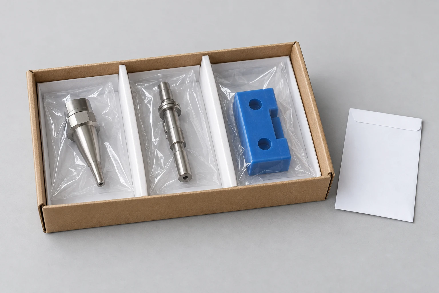
Individually protected machined components separated in a shipping tray

Working surfaces separated

Individual separation or suitable cushioning prevents part-to-part contact on specified faces. Protection for an open bore or projecting nozzle is selected for its geometry and agreed cleanliness requirements.

Variants clearly identified

Part numbers distinguish similar nozzles, guide profiles and changeover nests. Where traceability is required, the agreed lot reference connects the label, material record and dimensional report.

Replacement revisions controlled

A new drawing revision or material grade remains identifiable during repeat supply. Older and revised components should not enter the same replacement stock under an ambiguous description.

Food equipment machining FAQs

Can the same nozzle serve liquids and products containing particles?

A nozzle selected for a thin liquid should not automatically carry over to a product containing particles. EHEDG notes that equipment cleanable with liquids may not be cleanable with particle-containing products. The equipment team needs to reassess passage geometry and the cleaning process for the intended product before releasing a replacement design.

What does a 32 microinch Ra requirement mean?

32 µin Ra is approximately 0.8 µm Ra. It describes an average roughness parameter, not a polishing grit or a cleanliness test. This is a frequently cited reference for food-contact surfaces; the applicable equipment specification and named measurement areas determine the requirement for your part.

Is every blue plastic metal- or X-ray-detectable?

No. Blue color can improve visual recognition, while metal and X-ray detection require an appropriate formulation. Ensinger distinguishes ordinary blue grades from its specially detectable materials. Detection performance also depends on fragment size, the food and the detection system, so color alone is not an acceptance criterion.

Is a solid CAD model enough to specify the inside of a nozzle?

The model defines nominal shape, but may not identify internal texture, burr limits, transitions or the surfaces used for inspection. A drawing or agreed specification should identify those requirements and the final condition. Difficult internal access may require a geometry or manufacturing-route change before release.

Does protective packing mean the part is sterile or ready for aseptic filling?

No. Protective packing addresses transport and handling damage. A specified cleaning level, sterilization process or aseptic-use requirement needs its own method, acceptance criteria and responsible party. Those conditions cannot be inferred from an individually wrapped component.

Can a material certificate replace food-contact documentation?

A material certificate identifies properties or composition within its stated scope. Food-contact documentation addresses the particular material and intended conditions of use, including relevant formulation or authorization limits. FDA guidance makes those limits important; a generic metal or polymer name does not provide the same information.

PROJECT SUPPORT

Discuss your food equipment component

Share the drawing or model, quantity and equipment use. Identify product-contact areas, the specified material and finish, and any required records so we can define the component manufacturing scope.

Useful details for a quotation
The component

A drawing or model, or a short description of the part and its use.

The build

Quantity, current drawing revision and whether the parts are for a first build or replacement supply.

The delivery

Required surface condition, material documents and separately specified acceptance tests.

Not all details ready? Start with what you have; there is no need to complete a separate requirements checklist.

VETCNCCNC MANUFACTURING
English
Email us

Tell us about your project

Share your requirements and we will get back to you by email.

PDF, CAD or ZIP · up to 20 MB