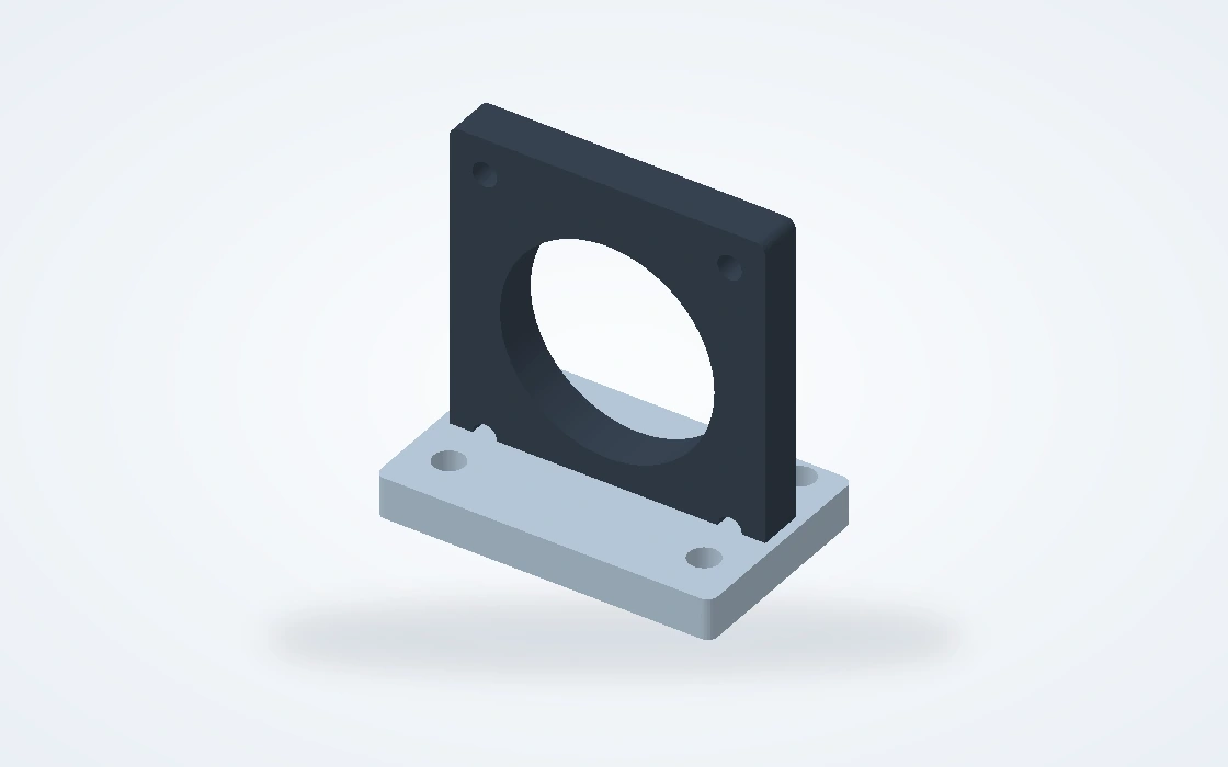
Instrument and device brackets
Brackets for instruments, navigation devices and auxiliary electronics. We machine the device opening, mounting base and fastener seats to the specified viewing angle and installation position.
Discuss this component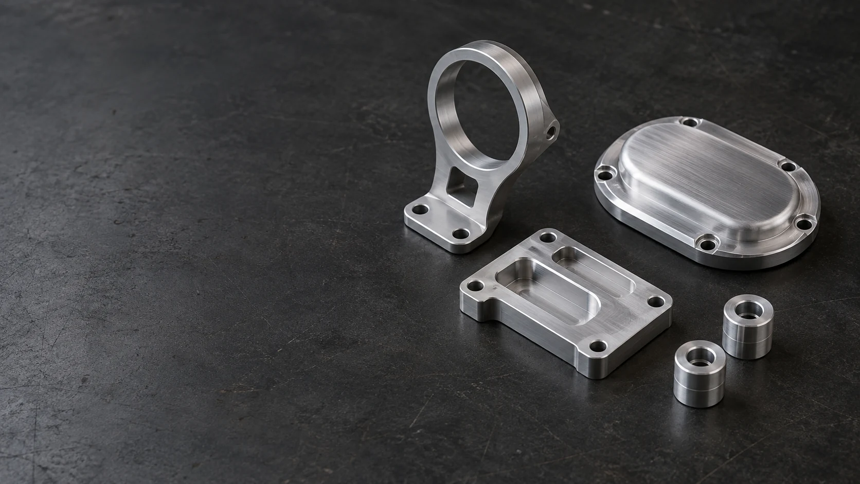
We machine brackets, covers, spacers, accessory housings and fixtures for motorcycle brands and aftermarket product teams. Your drawings define the mounting interfaces, visible surfaces and finished dimensions for prototypes and repeat component orders.
Our scope is drawing-defined components for your product or assembly process. We machine the mounting, locating and cover features; the product team retains the vehicle fitment and operating requirements.
Brackets for instruments, navigation devices and auxiliary electronics. We machine the device opening, mounting base and fastener seats to the specified viewing angle and installation position.
Discuss this component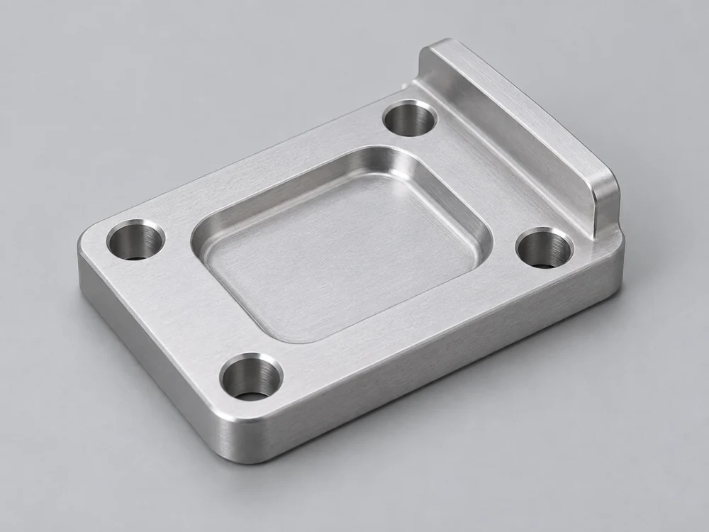
Interface plates for auxiliary equipment and body-mounted accessories. Hole pitch, offset faces and slots connect the product to its defined mounting points without relying on elongated holes to correct an uncertain pattern.
Discuss this component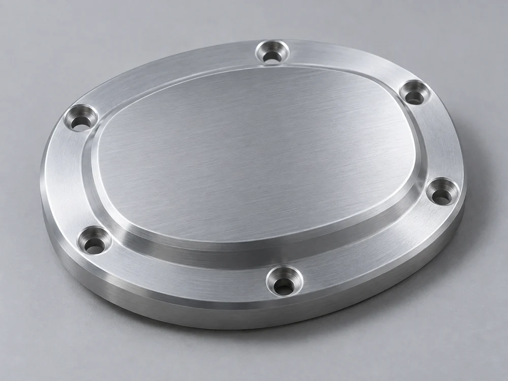
Separate covers, decorative plates and protective housings made to the released design. Recesses and reliefs clear the parts behind the cover; visible edges and recessed fastener seats form part of its finished appearance.
Discuss this component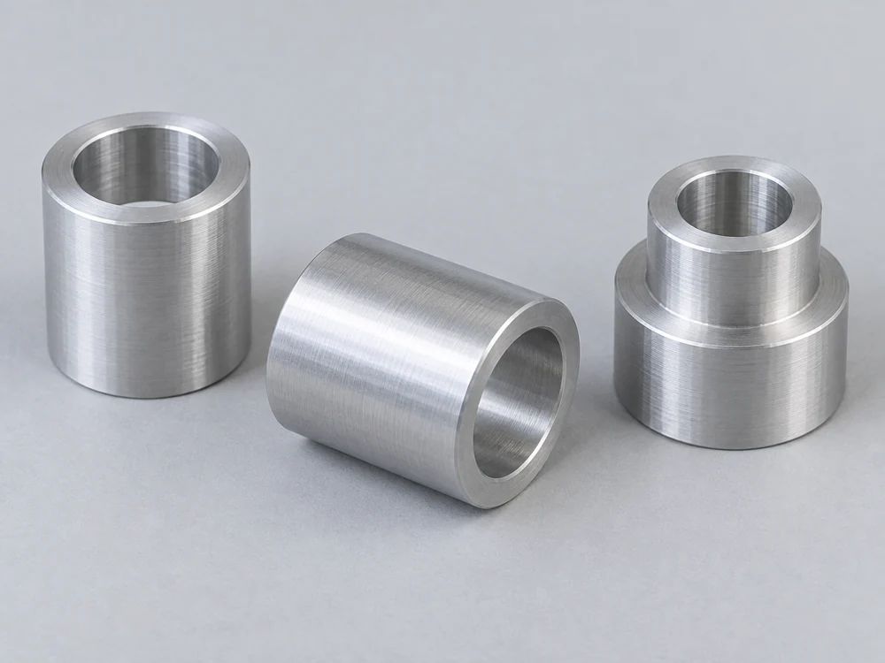
Turned components for accessory mounts, covers and assembly tooling. End-to-end length establishes the stand-off distance, while a shoulder or pilot locates the adjoining component.
Discuss this component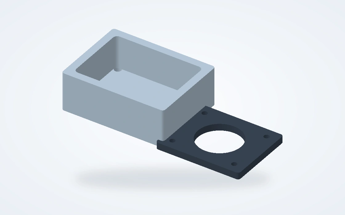
Milled housings for electronic accessories and instrument modules. We machine internal supports, cable or connector openings and cover interfaces to the component model and drawing.
Discuss this component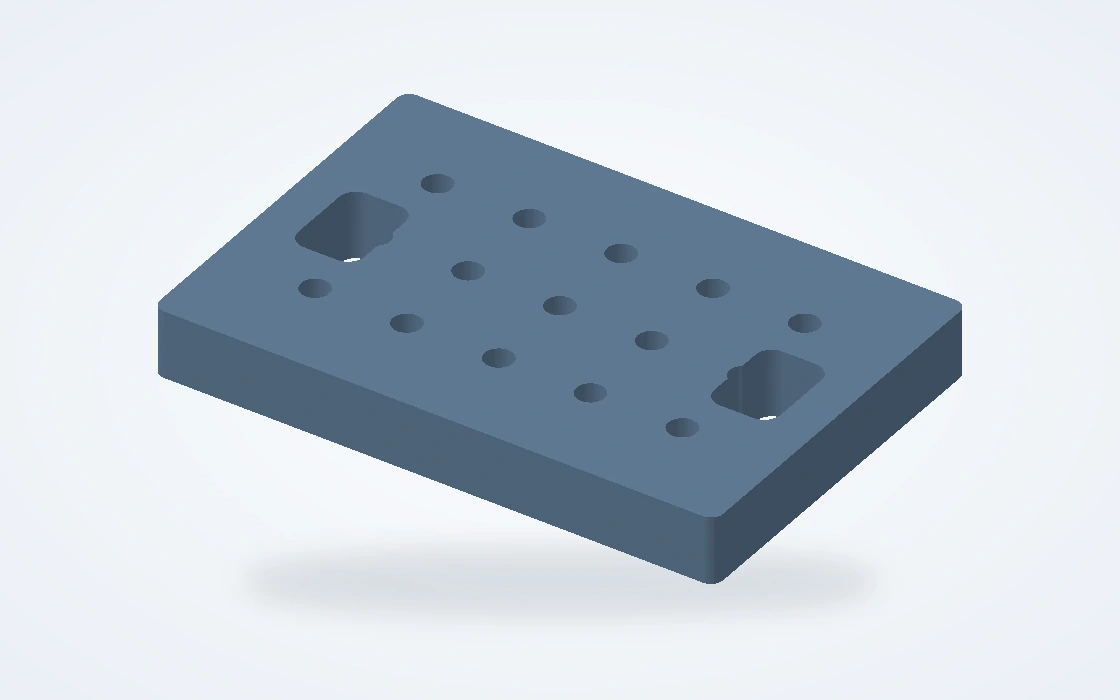
Fixture plates and removable locating blocks for building or checking your accessory assembly. Separate tooling details allow a worn locator or product-specific nest to be replaced without remaking the entire plate.
Discuss this componentA new accessory needs room on the motorcycle; a matched trim set needs a controlled appearance; a fixture needs to locate the product during assembly. We keep those three manufacturing tasks distinct.
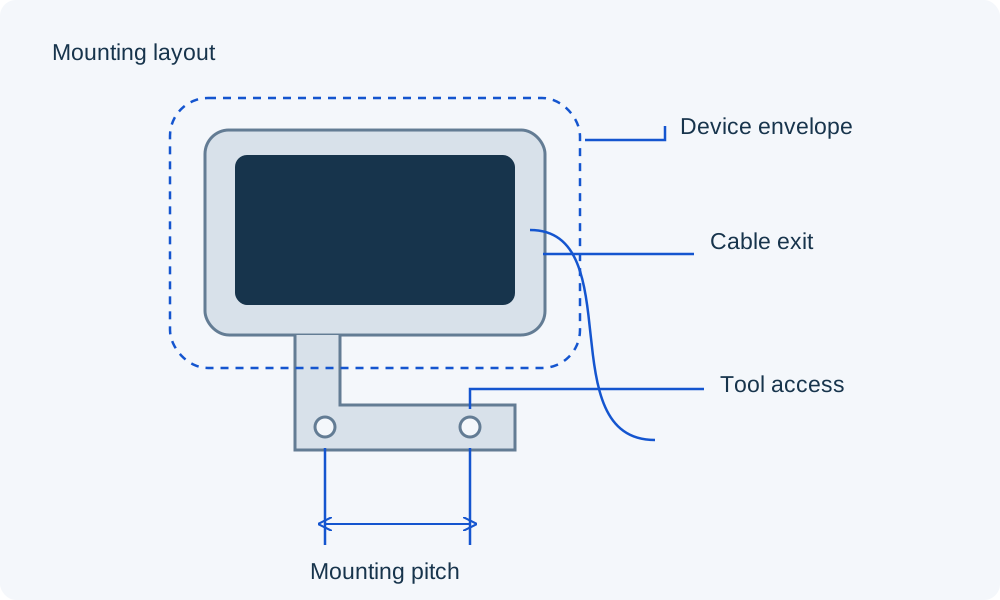
We machine the bracket or adapter around your defined mounting interface. The installation envelope should include the fastener head, washer, connector and the space needed to reach them with a tool.
For a steering-mounted accessory, the product team checks the surrounding clearance through the specified steering movement. A correct mounting-hole pattern alone cannot establish cable clearance or vehicle fitment.
Counterbores and nearby walls leave the specified tool path open after the accessory is in position.
Connector bodies, cable exits and the required service loop belong in the assembly envelope supplied with the part design.
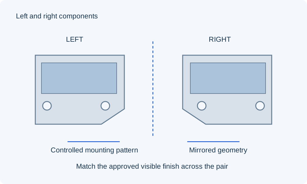
A left and right cover may share an outline while using different recesses or cable exits. We manufacture each from its own released model or an explicitly defined mirrored configuration.
For adjacent visible parts, the finishing definition identifies the show faces and their common texture. A cosmetic face does not automatically need the same machining tolerance as the mounting seat behind it.
Left and right references distinguish the actual mounting features, not just the direction in which a logo faces.
The drawing separates exposed faces, hidden pockets and allowable fixture-contact areas.
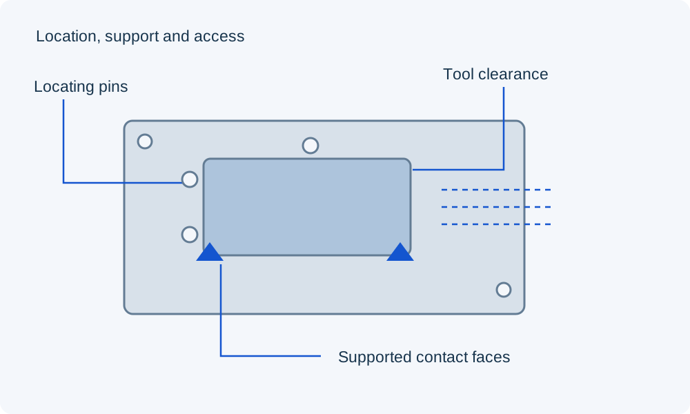
We machine fixture bases and locating details for holding brackets, covers or small subassemblies. Locators establish position; clamps hold the part against those references while leaving the fastening operation accessible.
For finished decorative parts, replaceable polymer contact pads can separate the metal fixture from the show face. Pad position and contact load remain part of the fixture design.
Locating features should reference the same mounting surfaces used by the accessory in its assembly.
A separately numbered pad or locator can be reordered when the product changes or the contact surface wears.
We distinguish a sample for checking installation space from a finished set for product approval. That distinction keeps early geometry changes from becoming unintended production requirements.
A first machined sample can check bracket position, screw access and interference with nearby equipment. The sample drawing identifies any omitted cosmetic finish so it is not mistaken for the released product condition.
Pilot sets bring the intended material, handed parts and surface treatment together. The product team can approve the installed appearance and final interfaces against one identified revision.
Repeat batches use the approved drawing and finish definition. A change to a hole pattern, spacer length or visible texture is kept as a new revision rather than mixed into the accepted batch.
Material choice changes component mass, stiffness and finishing behavior. We use the specified grade and condition; these references help distinguish aluminum parts, stainless details and polymer fixture contacts.
| Material reference | Parameter values | Part / stock context |
|---|---|---|
| 6061-T6 / T6511 extrusion | Yield ≥240 MPa; density ≈2.71 g/cm³ | Accessory brackets and cover bodies |
| 7075-T651 · Kaiser reference | Typical yield 503 MPa; tensile 572 MPa | Sheet / coil / plate reference; specified high-strength aluminum parts |
| 316L / EN 1.4404 | Elastic modulus 200 GPa at 20°C | Specified stainless spacers and mounting details |
| POM-C · TECAFORM AH natural | Tensile modulus 2.8 GPa; water uptake 0.05% | Fixture contact pads and removable nests |
Material references: Hydro Alloy 6061 extrusion minimum yield and typical density; Kaiser Alloy 7075 typical T651 properties; Outokumpu Supra 316L/4404 at 20°C; Ensinger TECAFORM AH natural (modulus at 1 mm/min; water uptake after 24 h at 23°C). Typical values are not specification minima.
We choose the machining route from the part geometry. Broad mounting faces, thin cover walls and short turned spacers each need a different way to hold and finish their working features.
Pockets, recessed fastener seats and mounting patterns are milled from the released model. On a thin cover, the support and clamping plan must allow the final face to be checked after it is released from the fixture.
CNC milling servicesWe turn bores, outside diameters and seating shoulders. For a spacer, both end faces and the working length matter: changing that length moves the component it supports even when the bore still fits.
CNC turning servicesMounts with angled seats or side-facing openings may need indexed or multi-axis machining. The drawing ties these features to the same assembly datums so separate setups do not define separate locations.
5-axis machining optionsWe concentrate dimensional control on the features that position the accessory. An outside contour may be cosmetic, while the mounting pattern and distance between seating faces determine where the part sits.
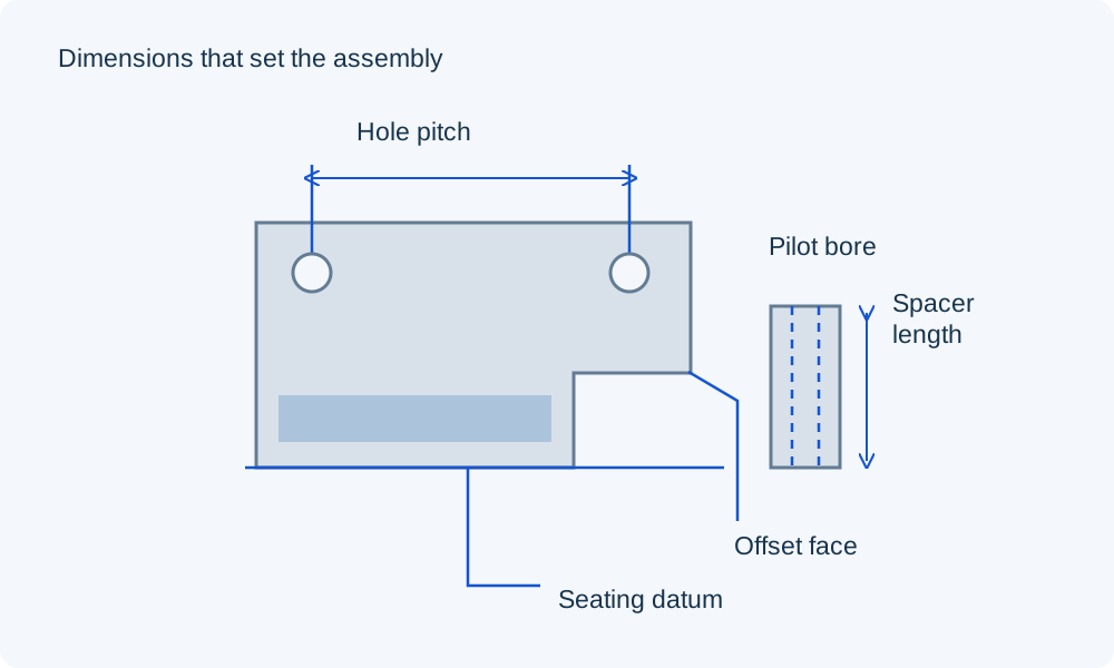
Hole positions are related to the mounting datum, including the offset from an angled or stepped face. A set of correct hole diameters does not establish the correct spacing or orientation.
The working length is measured between the faces that actually seat in the assembly. Recesses, washers and shoulders change that contact arrangement; overall length alone can describe the wrong stack.
A sleeve or spacer needs clearance for the mating part’s corner radius. The intended face must reach its seat without first contacting the radius or a chamfer edge.
The drawing states whether a fitted bore or thread is masked, coated to an allowance or finished after coating. The accepted dimension refers to that final condition.
We keep cosmetic treatment separate from functional fits. An exposed cover, a threaded hole and a locating bore can require different treatment on the same part.
Visible tool marks, edge breaks and any subsequent surface preparation follow the finish definition. A uniform exterior treatment should not remove a locating edge or alter a specified mating surface.
Anodizing changes aluminum dimensions. We use the specified coverage and dimensional allowance for bores, threads and mating faces, including areas that must remain uncoated.
We separate the designated show faces from hidden and fixture-contact surfaces. The order can identify an approved texture and color-range sample for the finishing scope, together with any acceptable rack-contact locations.
The table gives selected drawing references for accessory mounts and tooling. They apply only when the drawing calls for that size band, fit class or thread; they are not default dimensions for every motorcycle part.
We connect the measured feature to its assembly datum and final surface condition. Size checks, location checks and appearance approval answer different acceptance questions.
| Part feature | Parameter / condition | Acceptance method |
|---|---|---|
| Locating bore in a mount or fixture | H7, nominal >6–10 mm: 0 to +0.015 mm | Bore-size measurement; location checked separately |
| Mating sleeve pilot | h6, nominal >6–10 mm: −0.009 to 0 mm | Outside-size measurement after specified finishing |
| Metric accessory mounting thread | M6 × 1.0; M8 × 1.25 mm coarse pitch | Gauge to the stated thread class; check usable depth |
| Spacer working length | Axial length and end-face parallelism, mm; drawing limits | Measure between the named seating faces |
| Finished contact or visible surface | Ra, µm, where specified; separate appearance criteria | Surface-texture measurement; visual comparison for show faces |
Size and pitch references: ELESA+GANTER, DIN ISO 286 tables; Bossard, Metric ISO Threads (01-2025). Fit bands use nominal size >6 mm and ≤10 mm. The drawing sets positional, surface and axial limits and the final coating condition.
Our scope is component manufacture and the inspection stated in the quotation. Road-use approval, fatigue, vibration and installed-product performance remain separate requirements of the product program; a dimensional report does not establish those approvals.
A short spacer or reversed cover can look almost identical to the correct variant. We keep the supplied parts and their revision references identifiable through delivery.
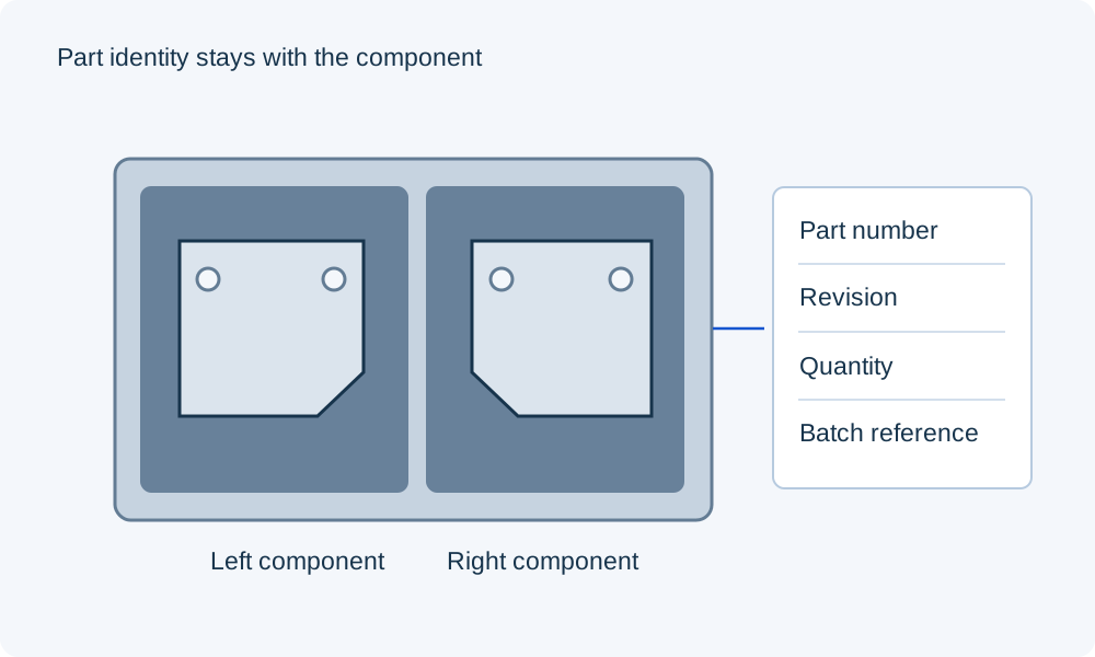
Separate packing prevents adjoining metal components from rubbing against show faces, finished edges or locating diameters in transit.
Distinct part numbers and quantities keep handed components and different spacer lengths separate. The shipment labels identify the revision supplied for each variant.
The repeat order retains the accepted finish definition and any approved sample reference. A change in alloy, surface preparation or color requirement is recorded with the new build scope.
A make and model can identify the intended application, but it does not define a custom part. We need the component model or drawing and its mating dimensions. Model year, optional equipment and existing modifications can change the installation, so we do not assign vehicle fitment from a catalog name.
A sample can help establish the geometry, but worn bores, compressed contact faces or previous modifications may not represent the intended dimensions. The manufacturing drawing needs agreed nominal dimensions and tolerances before a replacement batch is released.
Only where the controlled interfaces are the same. A shared outside shape does not prove that the mounting offset, hardware clearance and adjoining equipment match. We can keep variants under one project, with a separate part reference wherever the geometry changes.
The material substitution needs design approval. A higher strength value does not establish the same corrosion behavior, anodized appearance or finished fit. The revised drawing should retain the approved alloy, temper and finish together rather than order the part as unspecified high-strength aluminum.
Yes, the component drawing can define insert-ready holes. Specify the insert system and its required hole, thread and installation depth; a hole for an insert is not the same as the final mating screw thread. Insert installation must be listed separately if it is part of the requested supply.
A photograph is a useful visual reference, but it cannot fix color acceptance under different lighting. For parts that sit beside each other, use an approved physical color range and retain the alloy, temper and surface preparation. Those conditions affect the anodized appearance as well as the dye color.
Only the items listed in the quotation are included. Keep the machined bracket, spacers, washers, fasteners and any isolators as separate bill-of-material items, with quantities per kit. That also lets the design specify fastener length and engagement for the complete mounting stack.
The table notes retain the applicable grade, product condition and specification basis.
Share the part drawing, material, quantity and finish. Include the mating interface or assembly view where it defines the mounting position.