Skip to content
VETCNCCNC MANUFACTURING
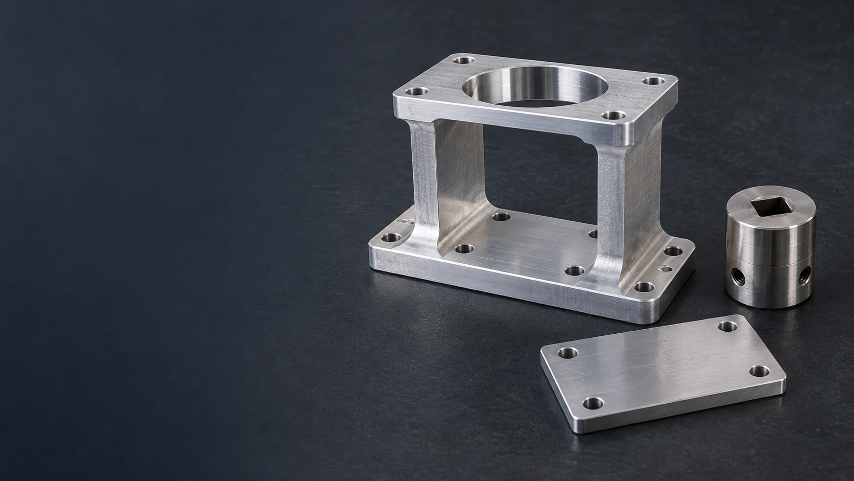
Machined actuator mounting bracket, square-socket coupling and four-hole mounting plate

Oil and Gas Equipment CNC Machining

We machine actuator mounts, drive couplings and instrument supports for oil and gas equipment builders. Our scope covers drawing-defined mechanical components and assembly tooling, with the mounting geometry, material condition and finished interfaces specified for your equipment.

  • Actuator interfaces
  • Instrument supports
  • Assembly tooling

Machined mounting, drive and support components

We supply the components between the selected actuator, valve and instrument—not a complete valve package. The mechanical interface and equipment drawings define each part in the mounting assembly.

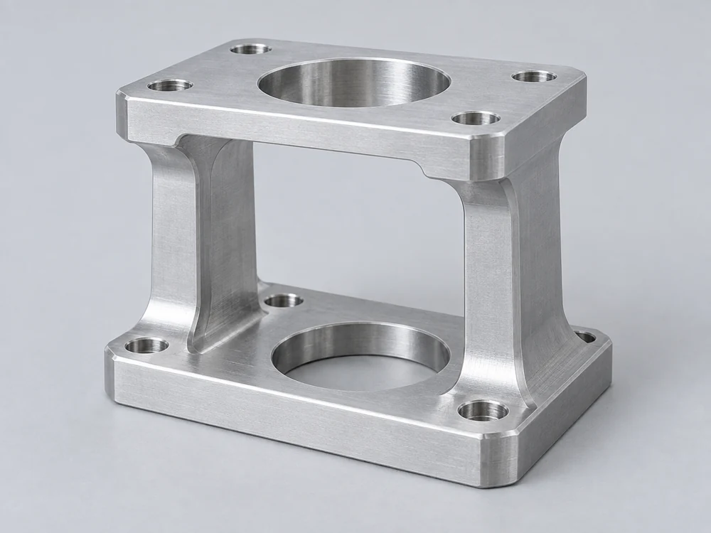
Open-bridge actuator bracket with parallel mounting flanges, a central bore and an access window

Actuator mounting brackets

Bridge brackets and mounting plates connect the actuator flange to the valve-side support. We machine the two mounting faces, bolt patterns and central clearance while retaining access to the coupling and fastening points.

  • Flange patterns
  • Mounting height
  • Coupling access
Discuss this component
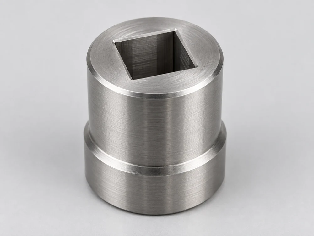
Short cylindrical drive coupling with a square socket and a lower shoulder

Drive couplings and adapters

Couplings connect the specified actuator output to the driven stem or shaft. The two drive forms, angular relationship and engaged lengths define the connection; the outside diameter mainly sets its clearance inside the bracket.

  • Drive sockets
  • Engagement lengths
  • Angular orientation
Discuss this component
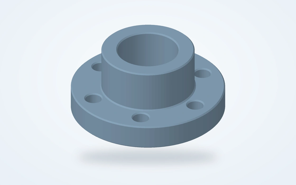
Circular mounting adapter with a raised hub, central bore and surrounding mounting holes

Indicator and sensor mounting adapters

Adapters place the position indicator or sensor over its intended drive axis. We machine the fixing pattern, locating hub and stand-off features to the selected instrument interface.

  • Sensor patterns
  • Locating hubs
  • Stand-off heights
Discuss this component
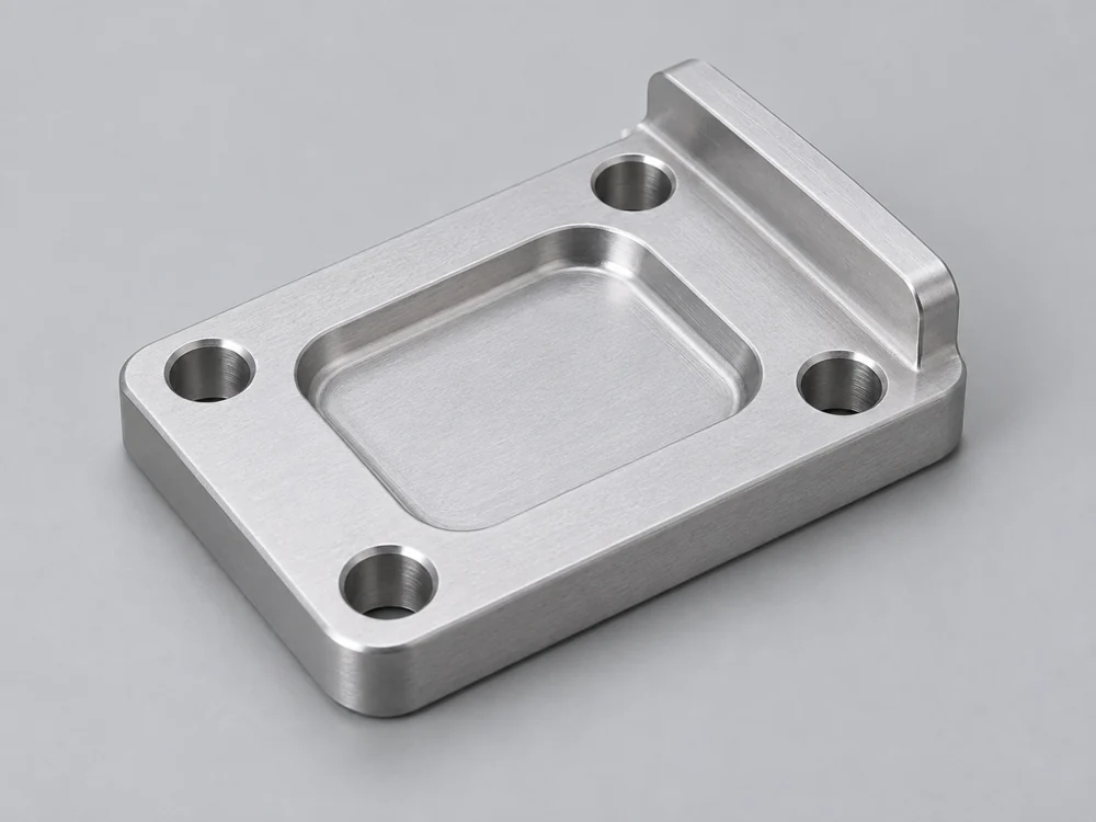
Rectangular instrument mounting plate with a recessed pocket and four round holes

Instrument support plates

Support plates carry local instruments and auxiliary modules on the equipment frame. Hole spacing, offset faces and edge clearance position the instrument without using its connected tubing or cable as a mechanical support.

  • Hole spacing
  • Mounting offsets
  • Service clearance
Discuss this component
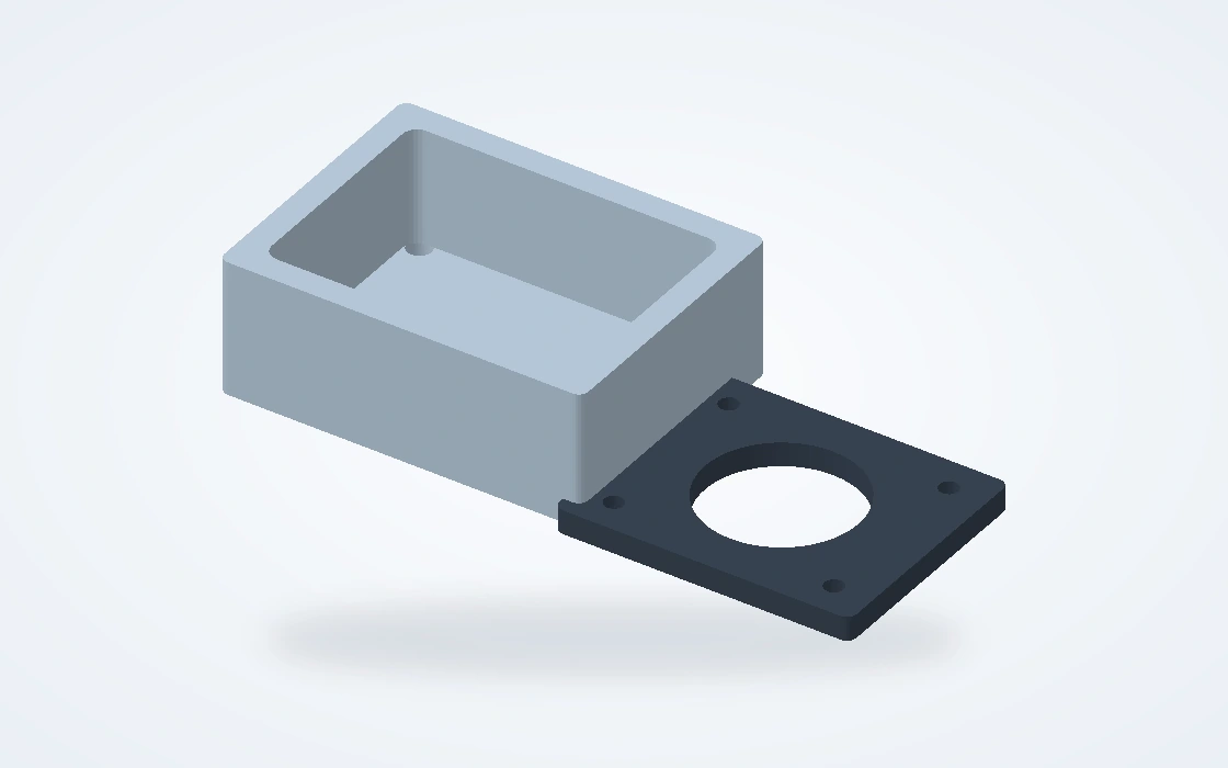
Empty machined equipment housing beside its separate cover

Covers and non-pressure housings

Separate covers and empty housings protect or support mechanical assemblies. We machine cover seats, fastening features and clearance openings; electrical protection and enclosure approval are outside this component scope.

  • Cover seats
  • Fastener recesses
  • Clearance openings
Discuss this component
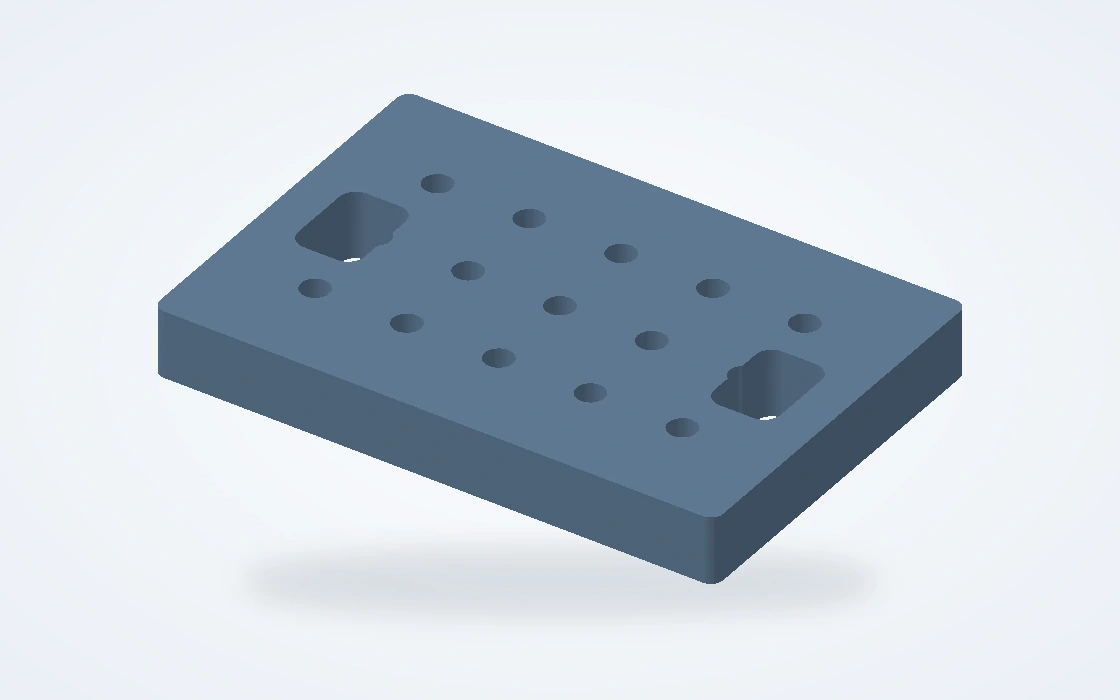
Machined fixture plate with a hole array and two slots

Assembly and inspection fixtures

Fixture plates and locating details position mounting components during OEM assembly or dimensional checks. The fixture references the actual bolt pattern, locating diameter or mounting face used by the component.

  • Interface locators
  • Support faces
  • Tool access
Discuss this component

Valve actuation, instruments and OEM tooling

These parts solve different installation tasks. The actuator mount carries a drive connection; the instrument adapter establishes a sensor position; the assembly fixture locates a component while the OEM builds or checks it.

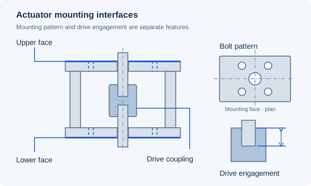
Open actuator bracket with upper and lower mounting faces, a central drive coupling, a bolt-pattern plan view and a separate drive-engagement detail

Connecting a selected actuator to the valve

We machine the bracket and coupling as separately defined parts. The bracket establishes the mounting position, while the coupling connects the two drive forms. Their dimensions must work together without making the coupling an unintended axial stop.

For a part-turn arrangement, the actuator model and selected flange option provide the starting interface. The valve-side attachment, coupling geometry and installation space complete the machining definition.

Two mounting interfaces

The actuator-side pattern and valve-side attachment remain separate details, even when their nominal flange sizes look similar.

Coupling access

An access window allows the specified fastening and assembly operation after the actuator and bracket are positioned.

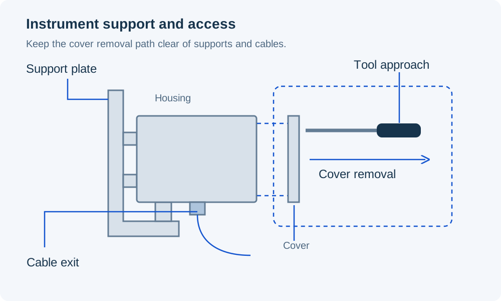
Side view of a supported instrument housing with a separated cover, clear cover-removal direction, fastener tool approach and cable exit

Positioning instruments and feedback devices

An indicator adapter needs the right mounting pattern and the right shaft height. The pattern locates the fasteners; the height establishes where the instrument meets the actuator output.

For frame-mounted instruments, the support geometry also leaves space to remove a cover and reach the fasteners. Cable glands, connectors and tubing bends are included in the installation envelope supplied by the equipment designer.

Selected device interface

Adapter dimensions follow the actual instrument variant. A matching bolt pattern alone does not establish the drive connection.

Maintenance access

The part design reserves the required removal path rather than only enough space for the assembled instrument.

Top view of a fixture showing three locating contacts, three supports beneath the part, a vertical tool approach to a bore and separate side access for a gauge

Locating components during assembly and inspection

We machine tooling that references the component’s working interface. A locating pilot can center an adapter, while a separate feature establishes its angular position before the mounting holes are fastened or inspected.

A fixture can also hold a bracket at a known mounting height for a coupling clearance check. It locates the components for that check; it does not replace a torque or equipment performance test.

Repeatable location

Defined support and locating contacts distinguish the seated position from the force used to clamp the part.

Accessible working features

The fixture leaves the coupling, mounting faces and specified measurement points reachable in the assembled position.

Interface samples, assembly sets and repeat orders

We keep geometry trials and released production parts under distinct revisions, especially when an actuator or instrument option changes during equipment development.

Interface sample

A sample bracket or adapter checks seating, fastener access and the available installation space against the selected mating equipment.

Assembly fit-check set

The bracket, coupling and indicator adapter are checked together for engagement and clearance. The OEM approves the combined geometry before it becomes the repeat-order definition.

Released component batch

The accepted models, material conditions and final dimensions define the batch. A replacement actuator option triggers an interface comparison before the same part numbers are reused.

Material references for mounts and drive components

A light instrument support and a loaded drive coupling do not have the same material requirement. We retain the selected grade and stock condition; the values below distinguish relevant material properties without assigning an equipment load rating.

Oil and Gas Equipment CNC Machining — material parameters
Grade / conditionReference parametersComponent / stock context
6061-T6 / T6511 extrusionYield ≥240 MPa; density ≈2.71 g/cm³Aluminum instrument supports and covers
316L / EN 1.4404Elastic modulus 200 GPa at 20°C; mean CTE 16 µm/(m·K), 20–100°CStainless mounts and instrument details
42CrMo4 +QT · Ovako 327AYield ≥650 MPa; 270–320 HBRound bar: stock Ø >40 to <100 mm; specified drive components
INCONEL alloy 625 · annealedNominal tensile 827–1,034 MPa; 145–220 HBRod / bar / plate, product sizes ≤4 in; specified special-alloy parts

Material references: Hydro Alloy 6061 extrusion; Outokumpu Supra 316L/4404 physical properties; Ovako 42CrMo4 variant 327A +QT round bar; Special Metals INCONEL alloy 625, annealed rod/bar/plate nominal room-temperature properties. Stock-size ranges identify the source data, not machining capacity. Nominal values are distinct from specified minima.

Machining the mounting and drive geometry

We separate broad mounting surfaces from rotational and angular drive features so each is checked against the references that matter in the assembly.

Mounting height, drive engagement and orientation

The component drawing needs to identify the features that position the equipment and transmit the specified motion. The outside shape alone does not define an interchangeable mounting part.

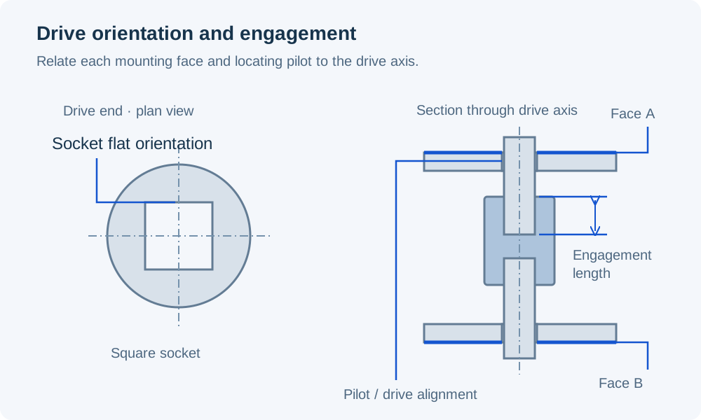
Square drive socket in end view beside a section showing engagement length, upper and lower mounting faces and locating pilots aligned to the drive axis

Mounting faces and locating pilots

A locating pilot and a bolt pattern do different jobs. The pilot defines the seating location; the fasteners secure the joint. A recess must also accommodate any specified spigot without preventing face contact.

Bracket height and coupling length

The distance between mounting faces determines the available drive engagement. The coupling must reach the specified drive surfaces while retaining the axial clearance shown in the assembly design.

Drive form and angular relationship

Square, keyed and other drive forms need their size, usable depth and orientation. We relate that orientation to the mounting pattern so the connection corresponds to the equipment’s defined position.

Fastening and removal space

Access openings and recessed seats leave room for the specified wrench, fastener and removal movement. A fully assembled model should not conceal a fixing that still needs to be tightened.

Finishing around working interfaces

Surface treatment follows the component and exposure requirements. The finishing scope also identifies which seats, drive surfaces and threads retain their specified dimensions.

Edges and coupling entry

Entry chamfers and edge breaks ease assembly without shortening the required working engagement. Coupling corners and internal reliefs follow the mating drive geometry.

Coating coverage and allowances

The drawing distinguishes coated exterior areas from masked locating and drive surfaces. Where anodizing is specified for aluminum, its dimensional change belongs in the allowance for the finished interface.

Final stock and treatment condition

A steel coupling specified in the +QT condition is not interchangeable with an unspecified steel blank. Any subsequent treatment and final hardness requirement remain tied to the released material and dimensional specification.

Reference dimensions for selected mounting interfaces

The following dimensions identify particular actuator and instrument interfaces. We check the supplied component against its released mating-equipment drawing, including the chosen flange or adapter option.

Pattern size, locating engagement and drive position are separate acceptance features. The inspection scope identifies their dimensions, datums and final surface condition.

Oil and Gas Equipment CNC Machining — feature specifications
Interface / featureReference dimensionsAcceptance basis
AUMA actuator-side F05 patternBolt circle Ø50 mm; 4 × M6 positionsEquipment drawing; hole locations and thread definition
AUMA actuator-side F07 patternBolt circle Ø70 mm; 4 × M8 positionsEquipment drawing; hole locations and thread definition
AUMA optional F07 spigotØ55 mm; projection 2.5 mmSelected spigot option; diameter, height and face seating
Festo SRBC A3 adapter30 × 80 mm pattern; shaft height 20 mmSelected device variant; pattern and height
Drive coupling engagement and orientationLength in mm; angle in degrees; drawing limitsMating drive geometry and mounting-pattern datum

Selected equipment references: AUMA SQ(R)05.2 / SQ(R)07.2–AC2, drawing U2.4020 revision 02; Festo SRBC September 2026 catalogue, A3 adapter. These are mating-equipment references, not universal interface dimensions. The component drawing sets hole form, positional tolerances, drive clearances and final surface condition.

Equipment qualification remains a separate requirement

This page covers machined mechanical components and tooling. It does not establish API certification, pressure containment, leak tightness or HPHT qualification. Any project qualification or test requirement must be identified separately from the dimensional machining scope.

Part numbers, revisions and packing

Two components can share a mounting pattern while using different heights or drive details. Their part references need to preserve those differences when they reach the assembly bench.

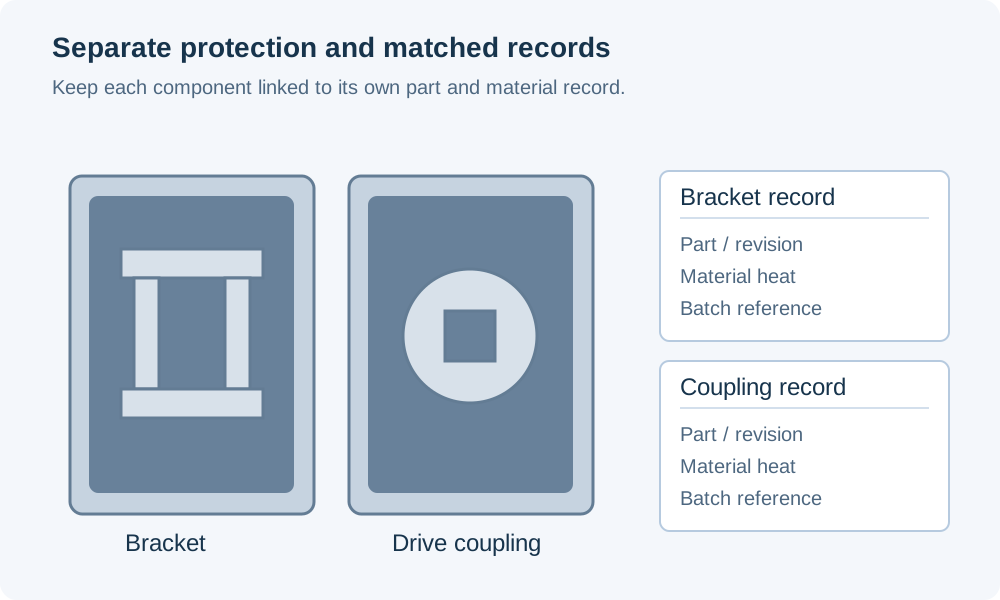
Actuator mounting bracket and drive coupling in separate protective compartments, each matched to its part and revision, material heat and batch records

Couplings and mounting sets

Component labels distinguish the bracket, coupling and instrument adapter. A mounting-set reference links the intended parts without treating visually similar variants as interchangeable.

Material and revision identity

The supplied part revision and specified material condition remain associated with the order. Where heat or batch records are required, the identification and document scope are defined with the purchase requirements.

Working surfaces protected

Packing separates locating pilots, drive sockets and mounting faces from neighboring parts. Protective contact does not conceal the component reference needed for receiving checks.

Oil and gas equipment machining FAQs

Is an ISO 5211 flange code enough to order a complete mounting kit?

No. The flange designation identifies only part of the connection. We also need the selected drive form and the valve-side attachment. ISO 5211 covers part-turn actuator attachments; the attachment of an intermediate support to the valve is outside its scope. A complete mounting drawing resolves that remaining interface.

Can the same mounting definition be used for a linear actuator?

No. A part-turn flange reference does not define a linear actuator connection. A linear arrangement needs its own mounting and driven-connection drawing, including the required motion and clearances. We assess the machined components from that definition rather than extend the part-turn interface values to it.

Can a square drive be supplied at a different angle to the bolt pattern?

Yes, a custom drive adapter can be defined that way. State the angle from a named mounting datum and identify the equipment position used as the reference. A square socket turned 45° relative to another has the same nominal size but a different connection orientation; the equipment designer must approve the intended arrangement.

Can one sensor mounting adapter support different indicator models?

Only when their fixing pattern, shaft height and drive connection agree. An interchangeable top plate or separate adapter variant may address a difference, but it should not force a mismatched shaft height into alignment when tightened. We machine the selected adapter geometry after those interfaces are defined.

Does specifying 316L or alloy 625 establish sour-service suitability?

No. An alloy name alone does not establish compliance with NACE MR0175 / ISO 15156. The applicable material condition and qualification depend on the specified service environment and standard requirements. The equipment owner’s material specification must identify those requirements; a general machining order does not supply that qualification.

Are fasteners and dowels included with machined mounting components?

Only when they are listed in the quotation. The bracket, coupling, studs, bolts, dowels and any retention parts should have separate bill-of-material entries. That prevents a machined-parts order from being mistaken for a complete installation kit and leaves the equipment designer in control of fastener grade and engagement.

Can a machined cover replace an approved electrical enclosure?

A mechanical cover is not a substitute for an approved electrical or hazardous-area enclosure. If the part belongs to such an enclosure, its design, permitted modifications and acceptance requirements must come from the responsible equipment manufacturer. We do not infer an IP or explosion-protection rating from a housing shape or material.

PROJECT SUPPORT

Discuss your mounting or drive component

Send the part drawing, material and quantity. Include the actuator or instrument interface drawing where it defines the component geometry.

VETCNCCNC MANUFACTURING
English
Email us

Tell us about your project

Share your requirements and we will get back to you by email.

PDF, CAD or ZIP · up to 20 MB