
Sample holders and carriers
Pockets, bores and open recesses support vials, containers or other defined sample formats. Retaining details and reliefs follow the sample envelope and the areas that must remain exposed.
Discuss this carrier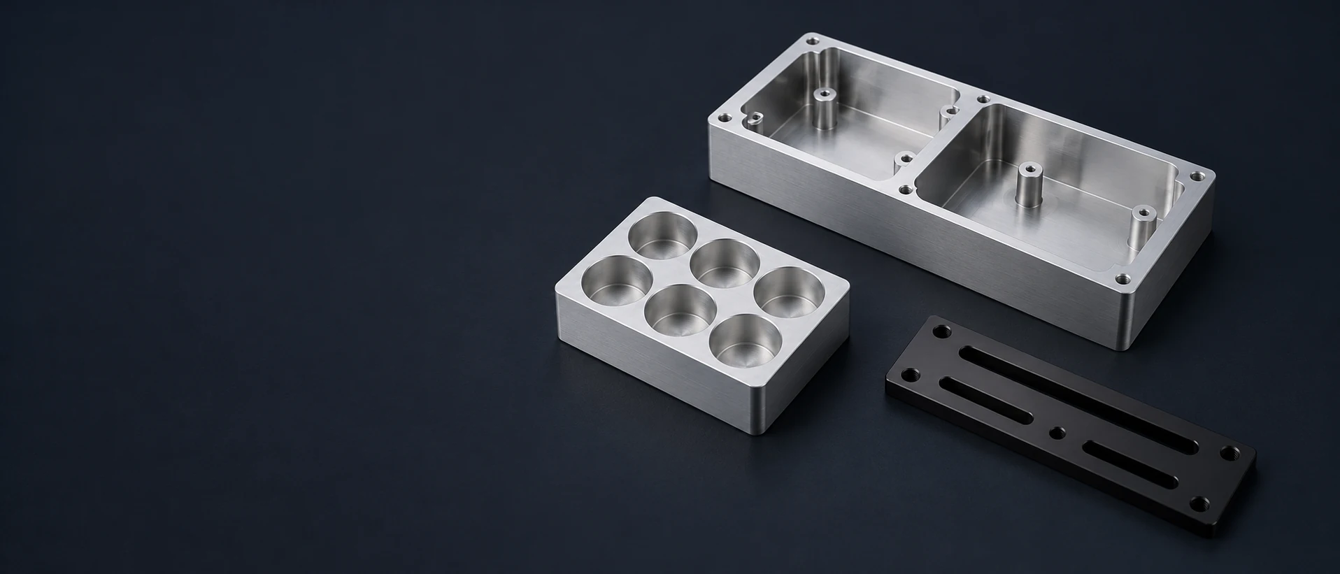
We machine custom sample holders, instrument housings, baseplates and adapters for research and analytical equipment. Our metal and plastic components support sample presentation, laboratory automation and experimental apparatus.
We supply the mechanical hardware around a sample, an instrument module or an experimental setup. Individual parts and related component sets can combine milled metal structures, turned details and machined polymer contacts.
Pockets, bores and open recesses support vials, containers or other defined sample formats. Retaining details and reliefs follow the sample envelope and the areas that must remain exposed.
Discuss this carrier
Machined plates provide mounting patterns, local support faces and locating features beneath instrument modules. Steps and recesses leave space for adjoining modules, fasteners and routing.
Discuss this baseplate
Empty milled bodies combine internal compartments, component bosses and cover interfaces. Openings connect the housed modules to cables, tubing or other externally mounted hardware.
Discuss this housing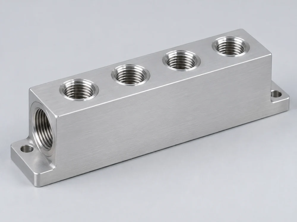
Blocks with drawing-defined ports and connected passages provide mechanical interfaces for an instrument’s selected fittings. Mounting ears or fixing holes attach the block independently of its tubing connections.
Discuss this block
V-blocks, nests and support pieces position specimens in research and measurement apparatus. Contact faces and retaining features follow the specimen geometry and the defined test setup.
Discuss this fixture
Slotted plates and interface blocks connect laboratory modules or carriers to an existing deck or frame. Hole patterns, stand-off faces and access openings match the defined receiving equipment.
Discuss this adapterA carrier loaded by hand, a plate transferred between instruments and a specimen mounted for measurement place different demands on the surrounding hardware. We machine the components that connect those tasks to the instrument.
A machined carrier can bring several containers into one loading unit. A regular array suits indexed sample presentation; shaped pockets can instead locate a particular sample assembly.
The holder can support the lower container body while leaving the region used for analysis exposed. That contact arrangement follows where the instrument actually observes or accesses the sample.[1]
Finger reliefs and an accessible lifting edge let the operator insert or remove the container without pulling against a fragile cap or connector.
Visible position marks can follow the instrument’s loading map, keeping orientation identifiable when a carrier is moved between the bench and the instrument.
Custom mounting adapters connect an existing laboratory module to the receiving deck or frame. The machine-side pattern and the module-side envelope can remain separate when a device is replaced or moved within the workcell.
A machined riser or stepped adapter can establish a module’s installed height without a loose stack of spacers. Its support face becomes part of the receiving station’s mechanical definition.
Access below or beside the carrier leaves room for the chosen handling fingers to engage and release it without striking the locating stops.
The complete carried outline is checked against neighboring stations and guards; a base footprint alone does not describe that swept space.
We machine support blocks and adapter pieces for the specimen and apparatus arrangement defined by the research team.
A bench-side base can remain common while sample-side inserts change between experiments. This keeps the equipment attachment separate from the contact geometry used for a particular specimen.
Open sides and reliefs can leave the prescribed probe, camera or loading path unobstructed around the specimen.
A keyed seat or offset locating feature can distinguish the intended direction of a holder. A symmetric outside pattern may otherwise allow the same piece to be installed in a reversed orientation.
Each build stage has a different output: a workable mechanical arrangement, a released component set, then repeated parts made to that definition.
Initial carriers and adapter pieces establish whether the sample loads, the support clears the measurement region and the apparatus can be assembled. A deliberately unfinished fit-check part is kept distinct from a contact part intended for laboratory use.
A pilot set brings the chosen contact materials, finish and mating hardware together for the customer’s instrument evaluation. Changes to sample pockets or docking interfaces become part revisions before repeat supply.
Identical carrier sets share programming and fixture preparation across the batch. More pockets, small intersecting passages, multiple setups, secondary finishes and added measurement coverage still increase the work required on each part.
A stiff instrument frame and a replaceable insulating contact need different material properties. Modulus and density help compare the named grades for those roles.
| Material / condition | Modulus and density | Component role |
|---|---|---|
| 6061-T6 / T651 aluminum | E 68.3 GPa; 2.70 g/cm³ | Lightweight housings and baseplates |
| 316L / 1.4404 · solution annealed | E 200 GPa; 8.0 g/cm³ | Corrosion-exposed metal supports |
| POM-C · TECAFORM AH natural | Tensile E 2.8 GPa; 1.41 g/cm³ | Replaceable carriers and guide inserts |
| PEEK · TECAPEEK natural, unfilled | Tensile E 4.2 GPa; 1.31 g/cm³ | Insulating supports and contact inserts |
References: Kaiser Aluminum 6061 sheet/plate data; Outokumpu Supra 316L/4404 data (E at 20°C); Ensinger’s named unfilled stock grades (polymer tensile E: ISO 527-2, 1 mm/min). E is elastic modulus. These short-term material values support comparison; geometry and loading determine component deflection.
We choose operations around the part’s functional features. Open sample pockets, annular adapters and intersecting ports need different cutting and deburring access.
Milling creates repeated sample pockets, V supports, housing compartments and mounting patterns. Tool reach and the material left beneath a pocket determine the practical route for an otherwise simple-looking carrier plate.[3]
CNC milling servicesTurning suits round spacers, bushes, support sleeves and end adapters. Faces and diameters that establish installed height or centering can be machined from a common setup before secondary holes or flats are added.
CNC turning servicesIndexed or secondary operations add ports and attachment details on several faces. Intersecting passages need an accessible route for removing internal burrs before the next assembly operation.
5-axis machining optionsThe carrier needs to locate the sample, seat in the instrument and allow its connections to be installed. These are separate relationships on the component drawing.

Locating contacts establish the sample position; a retaining screw or clamp keeps it on those contacts. Putting the retainer in a different place can change the contact pattern even when the carrier’s outside dimensions stay the same.[4]
The stops or locating holes that seat a carrier establish the origin used by its sample array. The array layout must be related to those docking features so the instrument can address the intended position.
A fitting needs room for its installation tool and tubing connection after the block is mounted. Port spacing and wrench access are considered with neighboring housings, rather than only on the loose block.
An insert needs its own locating seat and an accessible retention method. Its fixing hardware should not occupy the sample-contact area or prevent removal while the main carrier remains installed.
Sample contacts, locating interfaces and visible enclosure faces have different functions. Their surface requirements remain separate in the finished component definition.
Anodizing can protect aluminum carriers and housings while changing the surface dimensions. Working fits and locating contacts need their required finished size, with masked areas identified where coating is excluded.
A contact surface retains the specified roughness and edge geometry. General blasting or polishing is not extended across it automatically, because changing a narrow land or pocket edge can change how the sample is supported.[5]
Removal of machining residues and any specified passivation are separate from cosmetic texture. Sample-contact faces and internal passages carry their own condition requirement, specified apart from the brushed exterior.
We inspect the features selected by the drawing: sample pockets, docking locations, ports and contact surfaces. The applicable mating-labware and fitting references identify which interfaces the custom component must accommodate.
Reports connect the measured feature to its actual datum and finished condition. The sample-to-docking relationship is reported by connecting each measured feature to its actual datum and finished condition.
| Part / feature | Applicable reference | Acceptance detail |
|---|---|---|
| Microplate carrier envelope | Mating plate: 127.76 × 85.48 mm | ANSI/SLAS footprint; carrier clearance follows its mating design |
| 96-well carrier / adapter | 9 mm pitch; array origin 14.38 / 11.24 mm | Origin measured from the specified left / top plate edges |
| Selected fluidic port | 1/4–28 flat-bottom port family | Complete selected port drawing, including seat and passage |
| Replaceable insert seat | Drawing-defined seat and locating pattern | Size, orientation and accessible retention in final condition |
| Sample-contact surface | Specified roughness and edge condition | Actual contact land after the operations affecting it |
At the standards’ 20°C reference, ANSI/SLAS 1-2004 (R2012) plate dimensions allow ±0.5 mm along the sides and ±0.25 mm in the 12.7 mm corner zones. ANSI/SLAS 4-2004 (R2012) supplies the selected 96-well layout. These are mating-labware references, not carrier machining tolerances. The port follows the selected IDEX drawing; remaining feature limits follow the component drawing.
Vacuum or pressure service, controlled cleanliness and sample compatibility require their own specified acceptance. Each is confirmed through the acceptance specified for it.[6]
A carrier set can include externally similar inserts and supports for different samples. We keep those variants and the agreed delivery condition distinguishable on receipt.

Separate packing limits rubbing between sample-contact lands, projecting port edges and heavier baseplates. Covers or local protection can preserve exposed interfaces during handling.
Part numbers and revisions identify the correct pocket layout, insert or support height. Variant labels keep a visually similar piece from being fitted into the wrong sample arrangement.
The order identifies whether parts arrive for instrument assembly or a separately specified cleaning or finishing step. The receiving team can then distinguish the supplied condition from any later preparation.
No. Footprint defines the base outline; well-bottom elevation is covered separately in ANSI/SLAS 6-2012. The selected plate’s seating surface and bottom elevation determine where the wells sit above a carrier. Vertical sample position therefore follows from the plate's seating surface and well-bottom elevation.
The outer support may be reusable if it accepts the selected plate, but the addressed well pattern changes. ANSI/SLAS uses 9 mm spacing for 96-well plates and 4.5 mm for 384-well plates. A common outer footprint does not preserve the instrument’s well positions or its loading map.
No. The volume label does not define the tube’s outside diameter, taper, cap or contact height. Holders intended for several tube products need a released interface envelope covering each of them, with outside diameter, taper, cap and contact height stated.
No. Compatibility depends on the chemical, concentration, temperature, exposure and surface condition. Chloride-containing or strongly acidic conditions can require a different material or surface strategy. The selected chemical environment must therefore suit the exact grade and finished component.
No. IDEX lists flat-bottom 1/4–28 fitting families for both 1/16 inch and 1/8 inch outside-diameter tubing. The matching nut and ferrule establish the connection for the selected tube. Port thread alone does not identify the complete fitting or its assembled performance.
Not automatically. The fixture and the rest of the load train can deflect as well as the specimen. NIST’s mechanical-response guidance distinguishes specimen-gage movement from fixture displacement. A test method needs to account for that compliance; a dimensionally conforming support alone does not resolve it.
No. Traceability belongs to a measurement result supported by a documented calibration chain and uncertainty. NIST explains that a complete instrument's calibration is established on the instrument itself, through a documented chain and a stated uncertainty. A report for a machined part supports that part’s acceptance, not every result later produced by the instrument.
ISO/IEC 17025 addresses the competence of testing and calibration laboratories. It does not serve as a generic certification for a machined carrier or housing. If an order requires accredited measurement, the required measurement and the laboratory’s accredited scope must be identified separately from the component drawing.
Material, labware-interface and measurement references used for this page.
Share the mechanical drawing or model and identify the sample, module or receiving interface it supports. We will quote the required components and their finished delivery scope.
Current revision, mating labware or apparatus geometry and any sample-contact requirements.
Quantity for each carrier, housing, support or insert, including distinct sample-format variants.
Final finish, inspection records, timing and the operation receiving the parts.
An initial sketch can begin the discussion; the released drawing defines the manufactured part.
We use Google Analytics to see how this site is used. Analytics cookies are set only if you accept. Privacy Policy
