Skip to content
VETCNCCNC MANUFACTURING
Yellow brass windowed plate, open sleeve and formed L bracket on a dark surface

C27200 Brass CNC
Machining

Compare stock conditions

C27200 components with machined edges and working contacts

6 part examples

Windowed mounting plates

We machine the fixing holes, central opening and retained perimeter of a brass plate. Support near the thin section limits movement while the opening is cut, leaving the mounting face and finished edge defined in the released condition.
Machining on a formed bracket

A formed angle gives the bracket its two mounting faces. We locate the supplied shape and complete its specified holes or local contacts, relating them to the actual bent geometry rather than treating a flat blank as the finished assembly.

Smooth sleeves

A short sleeve relates its bore to the outside support and end faces. The selected stock form provides the wall for turning; a thin supplied tube and a bored solid blank need different support and material-removal routes.

Retaining rings

We turn the aperture, shoulder and retained face of a ring from its specified stock. The remaining section supports the inserted component, while local relief leaves its mating corner room to seat.

Mounting blocks

A small block can join a side opening to a fixing pattern. We machine the locating faces before relating the bore and holes to them, keeping the component position independent of an irregular raw-stock edge.

Adjustment knobs

A turned knob carries its internal fastening feature beneath the grip surface. We retain the selected threaded or bored connection and the usable contact length; the outer handling profile has its own finish requirement.

C27200 stock for cutting, forming and secondary machining

Strip retaining a forming operation

C27200 / CuZn37 is widely used for cold-formed strip components. Where a flange or bend remains in the route, the chosen temper must leave the required deformation available before final machining establishes the controlled contact. KME rates cold forming excellent but machining only fair.[1]

Route choice
The bend and final-cut sequence belong to the same released part.

Higher-strength rolled conditions

Work hardening raises the published tensile-strength range while reducing elongation. A stronger rolled condition can suit a detail that remains flat, but the same change does not preserve a softer strip’s forming response. The table separates the named R300 and R480 conditions.[1] [2]

Temper choice
Strength and remaining ductility change together.

Rod and supplied preforms

Rod, tube and strip references describe different starting products. For a sleeve or local turned detail we retain the selected product form and its own temper definition; a strip property row is not substituted for the rod certificate.[2]

Product definition
Grade, form, temper and applicable section stay linked.

Cut blank versus repeated forming

A flat blank with a machined window can avoid dedicated forming preparation for a development run. Repeated outlines may justify a separate blanking or forming route, with machining reserved for the contacts that need it. We quote the actual cut features or the agreed supplied preform.

Quantity and preparation
Local machining can finish a shaped blank without remaking every surface.
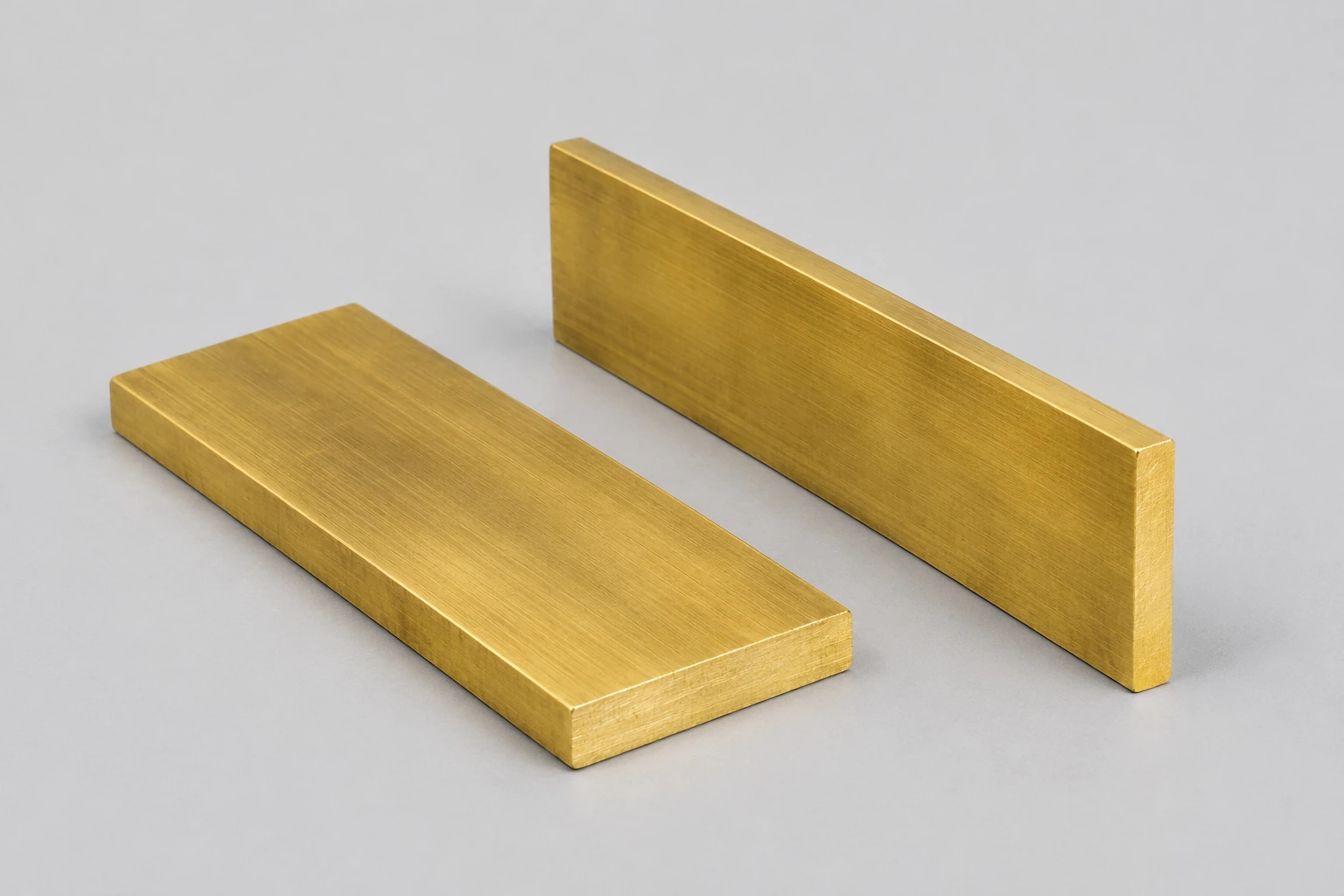
Two plain golden brass rectangular flat bars with visible cut ends
Golden brass round and hexagonal solid bar stock with visible cut ends

Yellow brass selected for the actual route

KME identifies CuZn37, CW508L and UNS C27200 on its named strip sheet. Its cold-forming role differs from a leaded free-cutting brass chosen mainly to break chips during heavy turning. We retain the ordered specification and temper rather than silently replacing C27200 with a faster-cutting alloy.[1]

A material designation does not itself establish an electrical contact rating or an end-use approval. The component definition keeps those functional requirements separate.

C27200 / CuZn37 named strip references
PropertyReference valueMaterial conditionUseful distinction
Tensile strength Rm300–370 MPaKME R300 stripLower-strength rolled condition
Tensile strength Rm480–560 MPaKME R480 stripHigher-strength rolled condition
Elongation A50mm38% minimumKME R300 stripRemaining ductility reference
Elongation A50mm3% minimumKME R480 stripNot the softer strip’s response
Elastic modulus110 GPaTypical annealed; 20°CMaterial stiffness reference
Thermal conductivity121 W/(m·K)Typical annealed; 20°CHeat-flow material reference
Thermal expansion20.2 µm/(m·K)Typical annealed; 20–300°CDissimilar-material fit input

KME CuZn37 / C27200 strip data, 10/2020, EN1652 mechanical reference. Elongation is A50mm; physical values are typical annealed material at 20°C, with expansion over 20–300°C. These references do not define a machined-part load rating.

Machining C27200 without losing the retained section

Thin plate section with supported mounting land and an opening

Window edges and fixing patterns

For a thin plate, milling removes the internal opening while the surrounding section is supported. We relate the fixing pattern to its mounting references and retain the specified corner radii instead of enlarging the opening through uncontrolled edge finishing.

Sleeve bores and end contacts

Turning establishes the selected diameter and end-face relationships. A thin-walled detail needs support that holds it without forcing the bore into its measured shape, especially when a later release changes the clamping load.

Features after forming

A formed blank can change where its holes or contact pads lie relative to the assembly. We locate the supplied condition from its working references and complete the released local features, leaving the bend and unaffected exterior within the supplied-part scope.

Plate support, sleeve clearance and final condition

Thin brass plate and sleeve acceptance conditionsSeparate the released plate, supported sleeve and installed mating contact.Mounting faceBrass componentMating detailDefined part and assembly state
The received component and its installed assembly use distinct acceptance conditions.
C27200 finished-feature acceptance
FeatureRequired relationshipAccepted conditionVerification
Windowed plateOpening, perimeter and fixing patternSpecified free or supported stateProfile, location and retained section
Formed bracketHoles / contacts across two legsReleased supplied or final formed stateSelected faces and feature references
Thin sleeveBore, outside contact and end facesLoose or defined installed stateSize, form and axial relationships
Coated contactFinal size and local coverageAfter included finishingDrawing limits and surface acceptance

Feature requirements for the delivered C27200 component

A window edge, a fixing pattern and a turned sleeve have different roles. Their limits follow the finished features, rather than one tolerance applied indiscriminately to all surfaces.

Working details for thin and formed brass components

Retained material at a fixing hole

The hole, nearby opening and outer edge leave a ligament that carries the fixing reaction. We preserve that released section through machining and deburring so enlarging an edge break does not consume the narrow supporting land.

Reference faces across a bend

The formed angle establishes the relationship between two legs. A hole position measured only from a raw edge can miss the installed mounting relationship; the released reference scheme connects both faces and the required attachment points.

Relief at an inserted component

An insert can touch an internal corner before its intended shoulder seats. A defined corner radius or local relief gives that edge clearance while retaining the face that carries the actual axial contact.

Grip geometry and fastening

A knob’s knurl or outer handling surface is separate from its retaining thread or bore. The section below the grip and the usable internal engagement remain in the component definition when the outer profile changes.

Discuss component requirements

C27200 parts in panels, guides and local hardware

Panels around an inserted module

A windowed plate locates its module through the selected opening and mounting pattern. Tool and fastener access are retained around the installed module rather than judged from the empty plate alone.

Formed mounting hardware

A formed bracket sets an offset between its adjoining surfaces. Local machining can finish the required fixing or locating contacts while leaving the released bend geometry intact.

Short guides and distance details

A sleeve or ring supports a selected mating member at its cylindrical or axial contact. The component follows the defined material and fit, while bearing life and wear performance come from the bearing design for that duty.

Manual adjustment details

The knob’s handling profile gives access to the adjustment connection. Its installed position still leaves the required finger and tool space beside the surrounding panel or frame.

Finished edges and selected surface coverage

Thin brass plate with four fixing holes and an open rectangular central window

Machined contact faces

We retain the specified texture on bores, shoulders and local mounting pads. Removing machining marks from a separate visible region does not require rounding a locating edge or polishing every working surface.

Edges around a thin opening

Deburring clears projecting metal from the window and holes while keeping the released edge break. Where little material remains, heavy edge finishing can change the useful land as well as its appearance.

Plated or tinned coverage

A selected coating defines which faces and contacts are included and when final dimensions are accepted. Masking, local coverage and the connection state are retained with the component rather than left to the general finish name.

Protected visible faces

We separate the finished plate faces and thin projections during packing. Part marking stays clear of working contacts, and any requested appearance sample identifies the actual visible surfaces.

Inspect the material state and completed geometry

Inspection concepts for a plate fixing pattern and two bracket legs

Retain product and temper identity

The material record keeps the specified C27200 product form and condition with the component. A later forming or thermal operation is identified where it changes the state used by the released drawing.

Check the actual mounting references

We check the opening, fixing pattern and local contacts from the selected reference faces. For a supplied preform, the inspection scope distinguishes the machined features from the shape retained from the earlier process.

Keep component and assembly results distinct

A completed dimensional check identifies the received geometry. Electrical contact, sealing, fatigue and other functional acceptance need their separately defined assembly condition and evidence.

What changes the cost of a C27200 component?

Blank size and window removal

A broad opening can remove much of the purchased plate while leaving a delicate perimeter. Stock use, support and the final cut sequence affect cost more than the finished component’s low weight suggests.

Number of controlled faces

A local cut on a formed bracket needs location and access on the supplied shape. Features on several legs or inside a short sleeve can add handling or another tool direction beyond the first flat setup.

Temper and finishing route

The ordered condition and any included forming or coating affect the work sequence. Final inspection after those operations avoids accepting an intermediate size that will change before delivery.

Quantity and common preparation

Programming, support preparation and the first accepted component share their cost across the quantity. A stable repeated outline can justify dedicated blank preparation; a small development order can favor flexible local machining.

From a C27200 development blank to repeat components

Release the complete starting state

The component definition identifies the selected product, temper and any supplied formed geometry before local machining.

Establish support and feature references

The first component resolves the cut sequence and inspection access for the retained plate, sleeve or bracket contacts.

Repeat the agreed complete route

The released material state, locating arrangement and included finish accompany the quantity instead of being inferred from the first outline alone.

Keep a changed route identifiable

A changed temper, bend or finish is retained in the new component revision so earlier fit hardware is not mistaken for the altered state.

C27200 brass component questions

Can the two bending orientations use the same radius in a harder strip?

Not by default. KME’s 90° reference for strip no thicker than 0.50 mm gives R/T values of 0.5 and 2 for the two listed orientations in R480; R300 is listed as 0 in both. Keep the selected bending direction and temper with the formed detail instead of transferring the softer condition’s bend reference to every strip.

Is one-third of tensile strength an operating vibration limit for a machined bracket?

No. KME describes an approximate temper-dependent bend-fatigue reference under symmetrical alternating loading for 10 million cycles at room temperature. A bracket with holes, bends, preload and a different loading history is not that test specimen. Its operating fatigue acceptance needs the actual component arrangement.

Does general corrosion resistance make an ammonia-containing cleaner acceptable?

No. KME identifies stress-corrosion cracking in cold-formed CuZn37 under tensile stress in the presence of agents including ammonia, amines and ammonium salts. Assembly can introduce that stress after manufacture. The cleaning and installed condition therefore matter together; a visually unchanged brass surface is not approval of the exposure.

Can C27200 be treated as a dezincification-resistant water-fitting grade?

Not from this designation. KME identifies possible dezincification with high-chlorine water and low carbonate hardness. Resistance under those conditions needs the released material and exposure requirements for the water in question. A water-contact design needs the appropriate released material and exposure requirements rather than a generic yellow-brass substitution.

Will machining a pre-tinned strip leave tin on every new edge?

No. KME lists hot-dip-tinned strip as a delivery form, so the coating is present before subsequent material removal. A newly milled window or drilled hole exposes a new cut surface. If those edges also require tin, the component needs a defined coverage and finishing sequence that includes them.

Can one H02 tensile-strength value cover every rod diameter?

No. Its Ms63b / C27200 sheet lists minimum tensile strength 375 MPa for the 3–12 mm diameter band and 350 MPa for the 12–18 mm diameter band in H02. The same temper name does not erase the product’s section band. Use the applicable incoming rod reference rather than extend the smaller-section value.

PROJECT SUPPORT

Discuss your C27200 brass component

Send the part drawing, selected product and temper, any supplied formed blank, quantity and final contact requirements. We can quote the local machining and included finish for that released component.

Technical references

Sources for named strip and rod conditions, processing distinctions and product scope.

  1. KME — CuZn37 / C27200 strip data, 10/2020EN1652 condition-dependent properties, bending references and specific environmental and processing behavior.
  2. Bedra — Ms63b / C27200Named rod-diameter and H02/H04 reference values, with product-specific delivery conditions.
  3. Millard Wire & Specialty Strip — C27200 specification sheetWrought-product fabrication routes including drawing, forming, shearing and swaging.
  4. ASTM International — B36/B36M-23Scope of the brass plate, sheet, strip and rolled-bar product specification.
VETCNCCNC MANUFACTURING

Get a Quote

Upload Drawing

*Required fields

Acetal part geometry illustration

Enlarged part geometry illustration

AI-generated part illustration.

English
WhatsApp Email us

Tell us about your project

Share your requirements and we will get back to you by email.

PDF, CAD or ZIP · up to 20 MB