Instrument mounting plates
Mounting holes and reference faces position an instrument across a defined span. A relieved underside can reduce mass while retaining material beneath the locating contacts.

Mounting holes and reference faces position an instrument across a defined span. A relieved underside can reduce mass while retaining material beneath the locating contacts.
A pocketed carrier locates optical hardware against machined shoulders. Its mechanical datums remain separate from optical alignment performed on the assembled instrument.
Turned spacers preserve a specified separation between mating faces. End-face parallelism and the working length matter alongside the nominal diameter.
A sleeve provides an axial seat and central bore. The flange-to-bore relationship establishes how the inserted component sits against its mounting reference.
A machined gauge body carries measuring or locating contacts. The accepted contact separation is related to its measurement temperature and support.
An Invar insert can control one local locating span within a different base material. Its fastening arrangement must accommodate the different expansion of the surrounding structure.
We quote custom Invar 36 plates, mounts, sleeves and instrument interfaces. The material’s low thermal expansion helps preserve a critical length, while machining stress, heat treatment and the mating assembly still affect the finished geometry.
The low-expansion alloy contains nominally 36% nickel. The selected product specification and thermal-expansion requirement define more than a general iron-nickel description.[1]
Annealed bar suits turned sleeves and spacers. A heavily reduced or asymmetric component can still move as material is removed, so final stability is managed through the machining sequence and any intermediate stress relief.[2] [1]
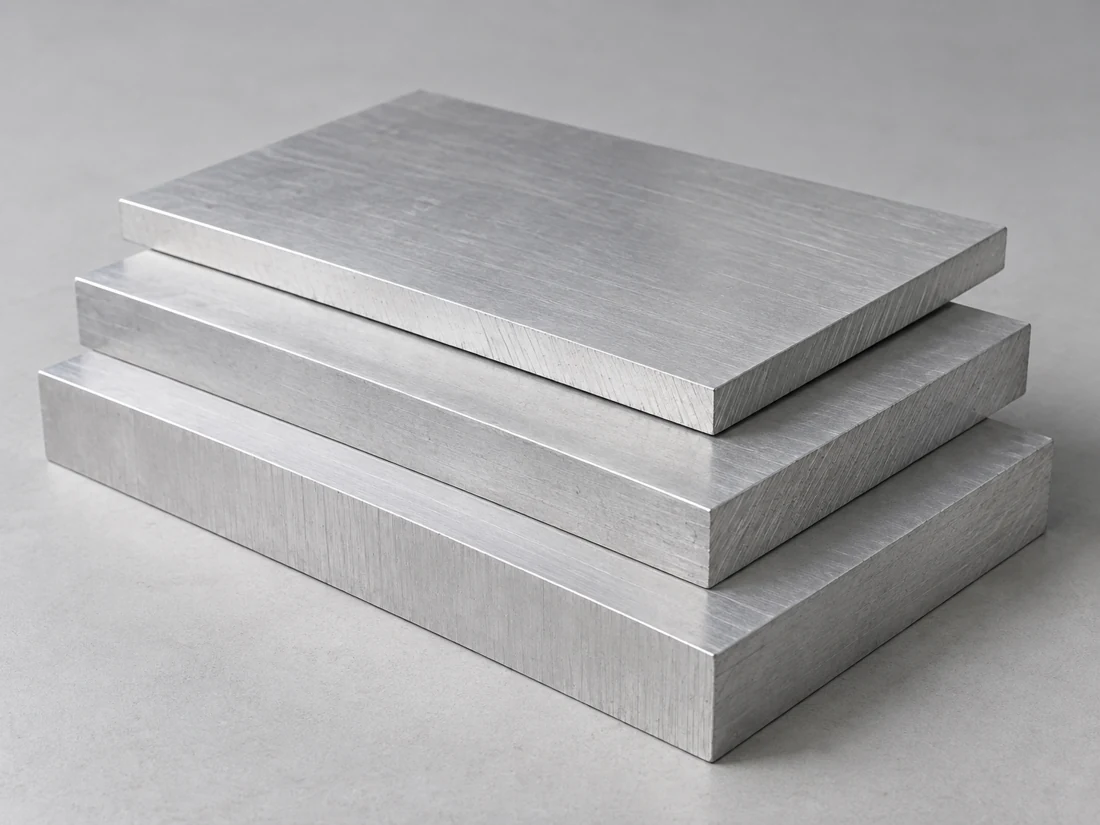
Plate supports broad mounts and reference bodies. Pocket depth and the distribution of retained material influence the machining stress left around the critical span.[3]
Stress relief or stabilization is a specified processing route, with temperature and sequence selected for the product. It must preserve the intended material behavior as well as the shape.

Invar 36 expands at different rates across different temperature intervals. Use the mean coefficient for the temperature span relevant to the component.[1]
Special Metals NILO36 supplies the named alloy reference; the data do not describe a finished VETCNC component.
| Property | Reference value | Condition | Buying relevance |
|---|---|---|---|
| Nickel content | Nominal36% | Fe-Ni alloy | Exact grade identity |
| Density | 8.11 g/cm³ | Producer reference | Component mass |
| Mean expansion | 1.5 µm/(m·K) | 20–100 °C | Interval-specific movement |
| Mean expansion | 2.6 µm/(m·K) | 20–200 °C | Wider-range movement |
| Tensile strength | 490 MPa typical | 20 °C; hot-rolled annealed bar | Reference stock condition |
| 0.2% yield strength | 240 MPa typical | Same annealed-bar basis | Elastic-load selection |
| Elongation | 42% typical | 20 °C;50 mm gauge length | Ductility reference |
Special Metals NILO/NILOMAG bulletin and Nickel Alloy Handbook. Typical values describe the named producer alloy and conditions. A finished-part thermal requirement uses its specified interval and processing history.

Roughing removes the major stock before the critical reference faces are finished. Any specified stress-relief stage belongs between the operations it is intended to stabilize.
Clamping a relieved plate flat can hide free-state distortion. Support and finishing use the accepted measurement condition rather than forcing the workpiece into a temporary shape.
NILO alloys work-harden and resemble austenitic stainless steels in machining behavior. Tool condition and a positive cut help avoid repeatedly loading a rubbed surface.[4]
Dimensional acceptance and a measured heat-lot expansion requirement are distinct deliverables.
| Feature | Requirement or reference | Accepted condition | Verification |
|---|---|---|---|
| Critical length | Drawing datum span | Defined temperature/support | Length measurement |
| Mounting land | Drawing flatness and relationship | After final thermal route | Datum-based geometry |
| Mating insert | Drawing seat and fastening interface | Free or specified assembled state | Fit/assembly check |
| Thermal behavior | Ordered CTE interval and limit | Specified lot and treatment | Separate expansion test |
Geometric and thermal acceptance answer different questions; material CTE is not a universal machining tolerance.
We quote the drawing’s working length, mounting faces and datum relationships. A reported room-temperature size does not by itself demonstrate performance through a thermal cycle.
A pocket can reduce mass without weakening the local support beneath a reference contact. Thin bridges beside the contact are more sensitive to clamping and stock-removal stress.
A constrained joint can transfer expansion from the surrounding material. A slot or compliant mounting choice is a design decision for the assembly’s actual load and locating task.
A coating changes the finished interface and can introduce another material into the thermal stack. Its thickness and masked areas belong with the final contact definition.
A machined gauge body supplies the defined geometry. Calibration of its measurement function requires its own method, conditions and traceable acceptance.
An Invar member can limit thermal movement across the measuring span. Other frame members and joints still enter the assembled error budget.
The mount locates the optics mechanically. Focus, alignment and thermal optical behavior remain properties of the complete optical arrangement.
A low-expansion insert is selected for its relation to the neighboring tooling and process temperature. A cure-cycle match is judged from expansion behaviour across the actual process temperature range.
A stable local reference can make a fixture useful across a controlled temperature range. Contact geometry and calibration conditions remain part of that reference.

The designated contacts retain their flatness and relationship after edge work. A general cosmetic polish can remove material from a calibrated span.
Deburring clears assembly edges without shortening an axial seating face or extending a relief into the working contact.
Any plating or other finish is matched to the drawing and thermal requirements. A coating is not assumed compatible with a low-expansion reference merely because it protects the surface.
Reference faces are separated from hard hardware and loose particles. The delivery condition identifies any protective oil or permitted cleaning before use.

The material record identifies the product specification and any required stabilization history. A nickel percentage alone does not prove the ordered low-expansion condition.
We inspect the specified contacts and their relationship in the defined setup. Free-state flatness and a clamped assembly position are recorded as different conditions.
Heat-lot CTE testing and instrument calibration require their own agreed scope. A dimensional report is not a thermal-expansion test.
Invar’s density and alloy cost make stock utilization significant. A deeply pocketed carrier discards more purchased material than a near-profile blank.
An intermediate thermal cycle and re-establishing datums add operations. They should serve the critical span rather than be requested as an undefined general treatment.
Recorded datum geometry, CTE testing or calibration add different kinds of work. Buying only the relevant evidence keeps the acceptance scope clear.
Programming and support preparation are shared across identical bodies. A new pocket layout can change stress release even when the outer dimensions remain the same.
A first component checks mounting access and the intended reference contacts. Assembly changes are resolved before the contact geometry is released.
The sample includes the specified stress-relief or stabilization sequence, so its inspected state represents the production route.
The accepted size and support conditions define the reference part. Any additional thermal or calibration result is attached to its own acceptance record.
Repeat orders retain the alloy, treatment route and working datums. A change to the mating base or operating range triggers review of that interface.
No. Invar36 is an iron-nickel alloy with magnetic behavior. It should not be selected as a nonmagnetic substitute merely because it has low thermal expansion.
Low expansion and heat conduction are different properties. Special Metals lists NILO36 thermal conductivity at 10.0 W/(m·K) at 20 °C. A carrier intended to spread heat therefore needs a thermal-path assessment as well as its dimensional requirement; low CTE alone does not make it a heat sink.
Not by name alone. These are different controlled-expansion alloys with different temperature-dependent curves. The intended expansion match and product specification must support the substitution.
Do not select filler from nickel content alone. Special Metals identifies NILO Filler Metal CF36 for welding NILO36 composite tooling. A welded carrier needs the selected filler and joining route matched to its expansion and final-condition requirements; machinability and weldability are separate manufacturing scopes.
A worn contact can shorten or shift the reference span. The replacement needs the intended geometry and calibration basis, rather than reproducing the wear found on the sample.
No. Invar is substantially denser than aluminum. The low-expansion benefit needs to justify the mass, stock cost and the stiffness of the retained geometry for the actual assembly.
Send the drawing, Invar product specification, quantity and critical reference span. Include the measurement temperature, thermal cycle, specified stabilization and any required CTE or calibration evidence.
Named low-expansion alloy data and the manufacturing/measurement decisions relevant to reference components.
We use Google Analytics to see how this site is used. Analytics cookies are set only if you accept. Privacy Policy
