Stepped shafts
We machine journals, shoulders, grooves and end features for shafts supported by bearings or other locating components. The working diameters share the drawing’s axis and face references.
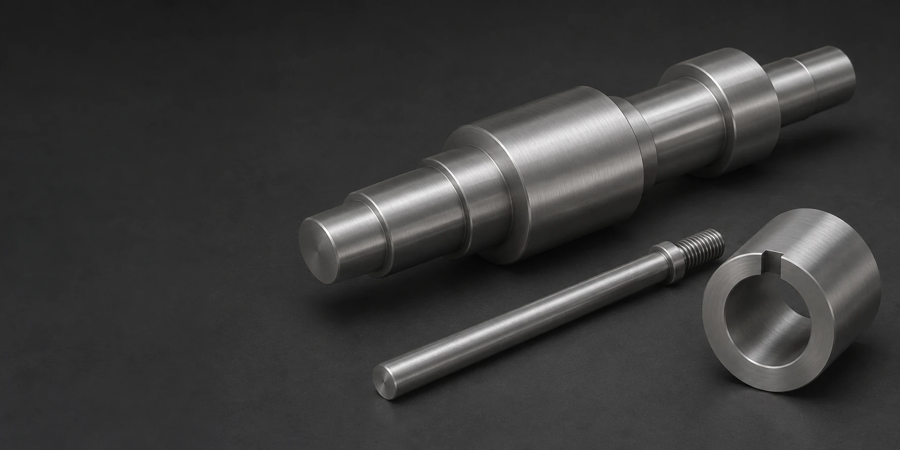
We machine journals, shoulders, grooves and end features for shafts supported by bearings or other locating components. The working diameters share the drawing’s axis and face references.
CNC turning brings the locating diameter and shoulder into their drawing relationship on the same hub. Specify the original quenched-and-tempered section and identify any further heat treatment before setting final dimensions.
A shoulder pin locates through its working diameter and seating face. A threaded or plain mounting end provides retention without replacing those locating functions.
A threaded end can retain a shaft in the surrounding assembly while a journal establishes its rotation axis. The thread relief and adjacent shoulder must leave room for the intended mating part.
A flanged sleeve combines a bore, outside diameter and axial-stop face. Each surface carries its own dimensional relationship to the mating shaft or mounting body.
We mill contact faces, mounting holes and local recesses in supporting blocks. Their retained section connects the working interface to the machine structure.
Our 39NiCrMo3 service covers machined components with the stock condition, treatment route and final features defined for the order. The required bulk properties and the geometry of the finished part are specified separately.
A +QT bar provides a defined mechanical condition before machining. It can suit a route that removes material while retaining the ordered bulk-property basis, with cutting and finishing planned for the actual hardness.[1]
An annealed blank permits the main geometry to be machined before the final thermal route. Lucefin’s reference lists a maximum of 240 HB for soft annealing; subsequent treatment and finishing establish a different delivered state.[1]
A prepared bar surface can reduce initial stock cleanup, while the final journal and mounting features are still machined to their own limits. The stock surface does not become a finished bearing seat simply because it is smooth.[1]
The producer’s +QT table gives different values as the original diameter or thickness increases. For example, tensile strength is 980–1180 MPa in its smallest section band and 880–1080 MPa for the larger band used below.[1]

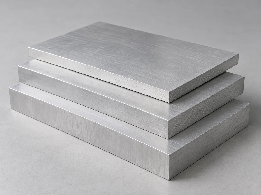
A strength value is only part of the material definition. The table also gives elongation, reduction of area and longitudinal impact energy for the stated +QT section at room temperature. These reference tests describe that material condition; a finished part’s notch, load path and service environment still determine its own acceptance needs.[1]
The material table uses Lucefin’s dated 2018 reference to EN 10083-3:2006, with its original section and test conditions retained.
| Parameter | Reference value | Unit | Applicable basis |
|---|---|---|---|
| Tensile strength | 880–1080 | MPa | +QT; section noted below |
| 0.2% proof strength | ≥685 | MPa | +QT; section noted below |
| Elongation A | ≥12 | % | Longitudinal; room temperature |
| Reduction of area Z | ≥45 | % | Longitudinal; room temperature |
| Impact energy Kv | ≥40 | J | Longitudinal; room temperature |
| Soft-annealed hardness | ≤240 | HB | +A reference condition |
| Carbon | 0.35–0.43 | mass % | Base-grade composition |
Lucefin 2018 reference. First five rows: hot-rolled +QT, 40 < d ≤ 100 mm or 20 < t ≤ 60 mm, longitudinal tests at room temperature, citing EN 10083-3:2006 in the original card. The separate +A and composition rows have their own stated basis.

We turn the journals, shoulders and retention details that establish a shaft or hub profile. The order in which those features are established follows the support available around the remaining section.
Keyways, flats, cross-holes and mounting faces connect the rotational body to other components. Their positions are related to the designated axis and face datums, not only to the rough outside shape.
A soft-machined part and a part cut from +QT stock have different routes. Where treatment follows roughing, the plan must leave access and material for establishing the required final seats after thermal movement.[1]
The final condition and datum support accompany the feature’s dimensional requirement.
| Feature | Required relationship | Delivery condition | Verification |
|---|---|---|---|
| Bearing journal | Diameter and axis control | Final machined/treatment state | Diameter and runout check |
| Axial shoulder | Face location and seating | Defined datum support | Length/face measurement |
| Keyway or cross-feature | Size, location and orientation | After included edge finish | Datum-related inspection |
| Protected external fit | Finished feature limits | Coated, masked or post-finished | Final-state measurement |
We inspect selected journals, faces and secondary features through the drawing’s specified relationships. The location and alignment of each working feature follow the drawing's specified relationships.
A shoulder transition connects sections of different stiffness. Its radius and the mating part’s clearance need to serve the load path and assembly together rather than being chosen only to simplify machining.
A keyway removes material from the shaft or hub section. Its depth, termination and nearby bore or shoulder affect the remaining geometry and the space available for the mating key.
A long, reduced-diameter section offers less support during cutting than a compact hub. The machining plan must account for that geometry and the datum surfaces available for final finishing.[1]
A retention groove close to a bearing seat needs the correct axial location and enough supporting material between features. A general edge break must not change its working profile or the adjacent face.
The bearings establish the rotating axis, while the drive connection transmits torque. The shaft’s journals, key or coupling feature and shoulder system must connect those functions coherently.
A pilot or bore can provide location while the bolt pattern supplies attachment. Separating those functions avoids relying on bolt clearance as a repeatable locating method.
A pin needs a working contact length as well as retention. The surrounding link width and support arrangement determine which part of the pin actually carries the load.
A support transfers load through its contact surfaces into the mounting arrangement. A correct hole pattern cannot compensate for an unsupported working face or an unsuitable surrounding section.

A journal’s roughness and surface direction are distinct from an exterior cosmetic finish. The drawing identifies the location and method required for a controlled contact surface.
A selected protective system needs coverage compatible with the assembly environment. Fits, threads and conductive or contact regions may need different treatment boundaries from the exposed exterior.
Deburring removes unwanted sharp or loose material while preserving the intended groove, thread lead and shoulder. Functional corners retain the form needed by their mate.
Finished journals and seating faces are kept clear of marking and handling damage. Packing supports the component without turning a protected working diameter into an unrestrained contact point.

The stock record identifies 39NiCrMo3, its delivery condition and relevant test basis. Any permitted machinability variant remains part of that material definition.[1]
We inspect selected size, location and axis relationships in the required delivered condition. The inspection method follows the controlled feature rather than treating every result as a single overall tolerance.
Fatigue life is established by a validation on the component itself. Any required component load or endurance validation has its own agreed assembly, method and acceptance limit.
The largest flange or shoulder can determine the purchased bar section. A long smaller journal can then require substantial removal even when the finished part is relatively light.
Machining +QT material differs from roughing an annealed blank before treatment. Slender sections, multiple orientations and final-seat access can add support and setup work.
Selected surface finishing, protective masks and recorded datum measurements add defined operations. Separate material or component tests also add their own work.
Programming and initial tooling preparation are spread across the quantity made together. An unchanged repeat can retain that basis, while a changed journal or material condition may require revised preparation.
The trial part establishes fit, access and seating within the actual mating assembly. Changes to a shoulder, groove or key interface become controlled drawing changes.
The accepted first part ties the finished geometry to the specified material and treatment state. Its acceptance basis identifies the selected results needed for production.
The released drawing, stock condition and included checks define the batch. A different starting section or treatment route is assessed against that definition before use.
A repeat retains the accepted material and interface definition. A revised bearing, coupling or duty requirement can change the component even if its external appearance remains similar.
No. The smaller finished journal does not retroactively change the original section’s heat-treatment response. Material acceptance uses the applicable starting/reference section and actual treatment record, rather than selecting a higher strength band from the finished diameter.
Not unless the acceptance specification expressly permits that method. Lucefin marks its +QT Brinell values as information; a hardness correlation does not independently establish proof strength, elongation or impact energy.
The drawing must define their angular relationship through a common reference. Independent dimensions from the shaft end establish axial position but cannot determine which way the keyway faces around the axis.
A uniform coating of thickness t on the complete outside surface adds 2t to the diameter. For example, 5 µm on each side adds 10 µm overall. Actual allowance and acceptance must use the specified process and finished limits, including any masking or final machining.
No. +QT identifies a quenched-and-tempered bulk condition. A separately hardened journal needs its own location, depth or hardness requirement and final-interface acceptance; it must be identified in the supply scope.
A component that needs a specified hard wearing case over a different core condition presents another material-and-treatment choice. 18NiCrMo5 addresses that case-hardening route, while 39NiCrMo3 is used for quench-and-temper bulk properties. The required contact and core behavior decide the specification.
Send the drawing, stock condition, final treatment and interface requirements, and quantity. We will define the machining route and the inspection included for your part.
Section, condition and test-direction notes for the stated reference data.
We use Google Analytics to see how this site is used. Analytics cookies are set only if you accept. Privacy Policy
