Straight wear strips
We mill straight UHMW strips with a defined running face, side profile and mounting pattern. Recesses keep the hardware beneath the contact surface, while end features locate the strip within the longer wear track.
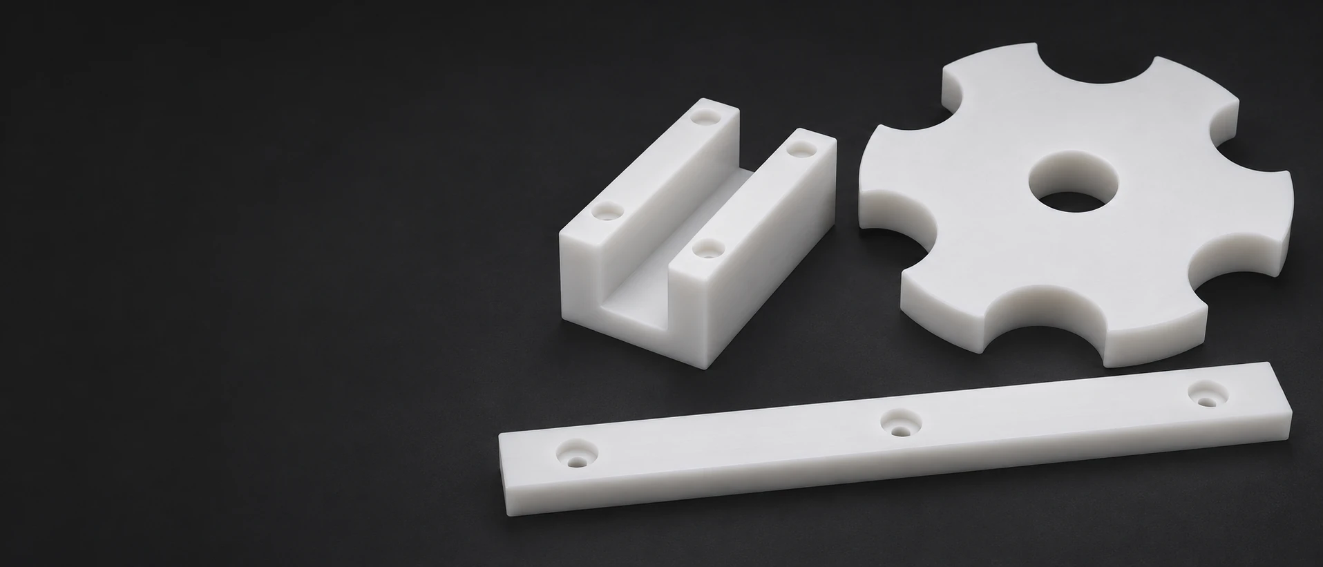
We mill straight UHMW strips with a defined running face, side profile and mounting pattern. Recesses keep the hardware beneath the contact surface, while end features locate the strip within the longer wear track.
Profiled chain-guide blocks combine a running channel with supporting sidewalls and mounting holes. We machine the specified channel section and local reliefs into the UHMW blank, including transitions required at the entry or exit.
We turn the bore, outside running diameter and locating flange of UHMW idler bushings. A stepped bore, shoulder relief or lubrication passage can form part of the drawing-defined geometry around the axle.
A guide pad presents a replaceable contact face against the moving member. We mill its thickness, perimeter and fixing features, with pockets or reliefs where the pad needs to clear the supporting frame.
UHMW scraper blades combine a working edge with an attachment section. We machine the specified blade profile, edge angle and mounting features so that the contact edge remains distinct from the body that holds it.
We mill product pockets around the starwheel perimeter and machine its center bore and fastening features. Pocket shape, spacing and angular position follow the drawing for the item being separated or transferred.
VETCNC quotes drawing-defined UHMW-PE milled and turned components for wear, guiding and handling duties. We confirm the exact stock product, feature feasibility and included inspection for the order.
A named virgin UHMW stock provides a useful starting point for comparing sliding-contact properties. The TIVAR 1000 natural data below describe that specific product; an unidentified sheet or a modified formulation does not automatically carry the same values. [1]
Added lubricant, static control and outdoor stabilization address different tasks. A change to one of these formulations is a material selection, rather than an extra finish on ordinary UHMW. We identify the proposed stock separately when the duty calls for it. [2] [1]
Plate and sheet suit strips, channel blocks, pads and scraper blades. The blank needs enough thickness and width to finish the working face and perimeter. A back-face relief can clear the frame while leaving a continuous wear face on the opposite side. [2]
Rod suits a bushing with a bore, outside contact diameter and flange on one axis. Starting close to that round envelope can reduce stock removal. A large center opening may justify another blank form if its product identity and remaining wall suit the part.


The friction coefficient describes resistance to sliding; wear rate describes material loss over distance. A low friction value alone does not tell us how long a guide will retain its profile. The mating surface, pressure and speed need to match the comparison being made. [1] [1]
The table keeps one named stock product and the conditions behind its published values.
| Property | Reference value | Test basis | Stated condition |
|---|---|---|---|
| Density | 0.93 g/cm³ | ISO 1183-1 | Natural virgin stock product |
| Tensile modulus | 750 MPa | ISO 527-1/-2 | Type 1B bar; 1 mm/min |
| Compressive stress | 6.5 / 10.5 / 17 MPa | ISO 604 | 1 / 2 / 5% nominal strain; 1 mm/min |
| Linear expansion | 200 µm/(m·K) | Producer reference | 23–100°C mean |
| Water absorption, 24 h | 0.1% by mass | ISO 62 | Water at 23°C; Ø50 × 3 mm disc |
| Sliding wear rate | 8 µm/km | Pin-on-disk procedure¹ | 3 MPa; 0.33 m/s |
| Dynamic friction coefficient | 0.15–0.30 | Pin-on-disk procedure¹ | Steel Ra 0.7–0.9 µm |
MCAM TIVAR 1000 Virgin UHMW-PE Product Datasheet, printed revision 07/03/2023, ISO columns. Most mechanical data are averages from dry specimens machined from 40–60 mm rod, otherwise 10–20 mm plate, at 23°C; compression uses Ø8 × 16 mm cylinders. Direction is unstated. ¹Procedure similar to ISO 7148-2 Method A, at 23°C and 50% RH; the pressure, speed and steel finish shown apply to both sliding rows. These are product-comparison values, not guaranteed purchase minima or finished-part ratings.

We support the retained section while machining the running face and profile. Excessive clamping can bend a strip against the fixture, leaving a different shape after release. A deep channel also changes how much support remains beneath the next cut.
Turning relates the bore, outside diameter and flange seat to the same axis. A thin wall needs a holding method that does not squeeze the bore out of shape; the finished interface is evaluated after the holding force is removed.
Sharp cutting geometry and a clear chip path help separate material rather than rub or smear it. Tool build-up and recut chips can affect the running surface or leave feathered edges. The cut and chip-removal method are chosen for the actual section. [3]
Feature limits use the drawing’s stated datums, support and temperature condition.
| Feature | Requirement or reference | Accepted condition | Verification |
|---|---|---|---|
| Guide channel or wear track | Drawing profile and path datums | Specified mounting support | Width/profile and transition check |
| Flanged idler bushing | Drawing bore, outside diameter and seat | Released or installed state as defined | Bore, diameter and face relationship |
| Reference thermal span | 500 mm, 23→43°C: ΔL ≈ +2.0 mm | Published mean coefficient held constant | Material-growth calculation |
| Thin wall or long strip | Drawing thickness and form limits | Defined support and measuring force | Check without squeezing or forced flattening |
Thermal estimate: ΔL = αLΔT = 200×10⁻⁶/K × 500 mm × 20 K = 2.0 mm. The source coefficient is a 23–100°C mean. Assembly clearance also depends on mating materials and restraint; this calculation does not set a required slot length or a manufacturing tolerance.
We quote the critical profile, bore and mounting relationships for the chosen UHMW stock and section. A long supported strip, a thin bushing and a starwheel pocket need different measurement arrangements; one general accuracy number does not define all three.
A joint should maintain the intended running level and direction. A step or projecting end can catch the moving item even when each separate strip meets its own thickness limit. Joint location and relative face position belong to the track geometry.
The usable wear layer lies between the original contact face and the highest retained hardware. Counterbore depth and the remaining material beneath it have different jobs; a deeper recess should not leave the mounting floor too thin.
A chain’s link plates, pins or rollers can occupy different parts of the channel envelope. Local relief lets the intended running element make contact while adjacent features pass freely. A single overall channel width cannot define every clearance. [3]
The blade angle and contact land control how the scraper meets the moving surface. The attachment section supports that edge, while its setting determines the working gap or contact. An unspecified sharp edge does not define that arrangement.
A guide supports the designated moving link or roller while the surrounding channel keeps the chain on its route. The contact section changes at curves, entries and returns; those locations determine where a plain strip or a profiled block is useful.
A guide pad separates a moving member from its support. The backing carries the pad while the exposed face supplies the replaceable sliding contact. The mounting arrangement must leave the pad seated across the region intended to carry that contact.
A scraper presents its working edge across the surface being cleared. Its mounting position and edge profile set the contact line; clearance around the blade gives displaced material somewhere to leave rather than collecting behind the edge.
Starwheel pockets receive the product and carry it through a defined arc. Pocket spacing works with the adjacent guides and transfer point, while the center mounting sets the wheel’s angular relationship to the rest of the handling mechanism.

The running face follows the specified texture and permitted tool-mark direction. A cosmetic matte finish is not a substitute for the required contact surface. Extra sanding or blasting can change the profile and is not an automatic finishing step.
Fine attached strands can remain at a profile edge or hole exit. We remove unwanted burrs without leaving loose material in a running channel. The finished edge condition is distinct from simply making a white surface look uniform.
A guide entry may need an edge break to lead the moving item into its path. A scraper instead retains its specified contact angle and edge land. General deburring must not round away the geometry that gives the blade its working contact.
A part number belongs on a permitted noncontact surface, away from the running profile. Finished parts are cleaned to the agreed requirement and separated during packing so that chips or hardware do not become trapped against the contact face.

We identify the specified UHMW product and any required modification with the part definition. The record distinguishes an approved change of formulation from an unchanged repeat, and is what identifies the material supplied.
A starwheel needs its pocket profiles and spacing related to the center and angular mounting datums. Checking one pocket diameter alone misses a pitch or phase error. For a guide segment, the corresponding checks relate the running profile to its mounting face and joints.
A dimensional inspection shows whether the released geometry was supplied. Actual running drag, wear and replacement interval need a representative equipment trial when they form part of acceptance. The material table does not itself demonstrate those operating results.
A long strip cut from a suitable plate layout uses stock differently from a bushing turned from a solid rod. A named modified grade or a stock route needed for a thin blank can also change material cost and availability.
A thin scraper, deep channel or long flexible strip can need added support during cutting. Underside recesses and cross-holes add setups, while a continuous profile accessible from one face is usually simpler to machine.
Controlled scraper geometry, selected running-face texture and recorded profile relationships add specific finishing or checking work. A service-life trial is a separate acceptance item with its own scope; it is not included merely by specifying UHMW.
Programming, workholding and initial profile checks are shared across identical parts made together. Several different guide sections still require their own preparation. An unchanged repeat can reuse the accepted basis rather than starting from another stock or profile definition.
An initial component establishes how the actual moving item enters, runs and leaves the contact profile. A change to the guide gap, scraper position or starwheel transfer geometry is resolved before that definition is released for the batch.
A representative wear component uses the intended stock product and mounting support. Where running performance is critical, the equipment trial supplies the application evidence before quantity is committed to that material and geometry.
The accepted drawing, stock identity and final feature requirements define the production run. Changes agreed during the trial are carried into the released revision rather than remaining an unrecorded adjustment on one sample.
A repeat references the same contact profile, stock product and inspection basis. A modified grade or revised joint is identified before it is mixed with earlier segments, so that replacement supply follows the intended track or handling arrangement.
No. That description alone does not identify an added lubricant. MCAM describes base TIVAR 1000 as self-lubricating, names a separate Oil Filled product with an oil additive, and identifies HPV as a grade with a built-in dry lubricant. The specified formulation determines what is actually in the stock, so name the grade when grease-free operation matters.
It is the comparison reference: the listed relative volume loss is normalized to TIVAR 1000 = 100. It does not mean 100% wear resistance or a particular replacement interval. Compare another index only on the same test basis; a sand-slurry result is not interchangeable with the table’s sliding-wear rate.
No. MCAM’s 3,000 ft·lb/(in²·min) entry is stated at 100 ft/min for a plastic thrust washer against steel, with pressure increased until deformation or the test’s temperature endpoint. Heat flow and contact behaviour follow the actual pressure, speed, counterface and cooling in your application. The 300°F endpoint in that procedure is not a permitted UHMW service temperature.
Only with a qualified bonded-joint design. Adhesives intended for UHMW can make bonding feasible, but the adhesive, surface preparation, joint geometry and differential movement all matter. Deleting the existing mechanical retention is therefore a design change, rather than an assumed equivalent attachment. The joint needs evidence for the actual loads and environment.
Not automatically. MCAM describes skived sheet as capable of end curl and blade lines, while its planed stock has a different gauge and surface condition. If those stock faces remain on the part, their flatness, thickness and texture must meet the finished drawing. Otherwise the blank and machining allowance need to accommodate finishing them.
They come from different contact tests. The 0.15–0.30 range uses a pin-on-disk-like procedure at 3 MPa and 0.33 m/s; 0.12 uses a plastic thrust washer against steel at 250 psi and 20 ft/min, with its own counterface condition. They are not the upper and lower bounds of one operating case. Use the test that represents the intended contact rather than simply selecting the smaller number.
Send the matching drawing and model, specified UHMW stock, quantity and required working-surface finish. Include the mating profile and any defined mounting, temperature or inspection condition so we can quote the intended component.
Named stock data, test conditions and manufacturing guidance used for the decisions on this page.
We use Google Analytics to see how this site is used. Analytics cookies are set only if you accept. Privacy Policy
