HDPE sleeves
We turn sleeves with a through bore, outer diameter and locating shoulder. The bore can provide clearance around a shaft while the shoulder sets the sleeve’s position in a plate or housing.
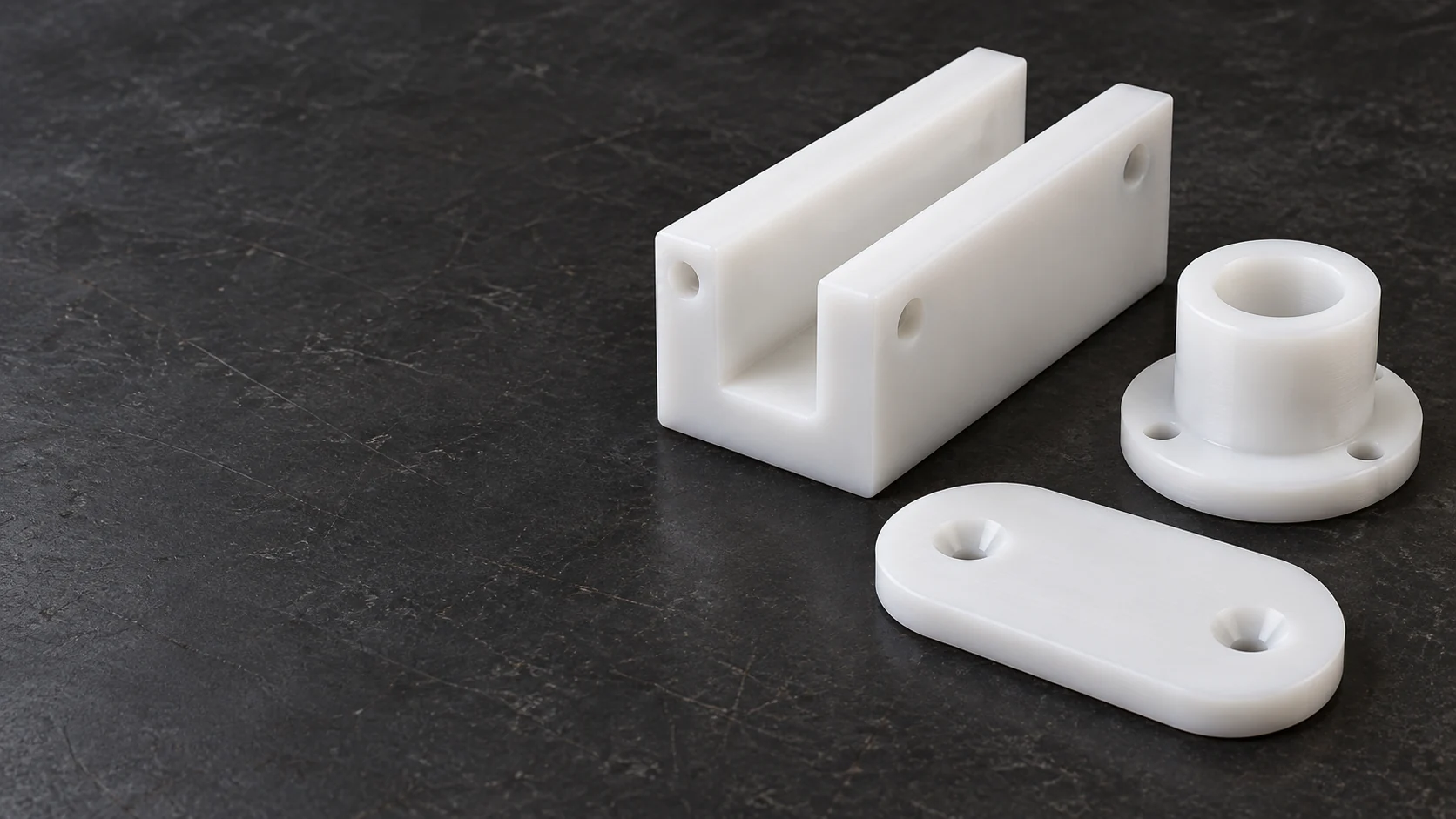
We turn sleeves with a through bore, outer diameter and locating shoulder. The bore can provide clearance around a shaft while the shoulder sets the sleeve’s position in a plate or housing.
Turned HDPE rollers combine a running diameter with an axle bore. A flange or groove can locate the moving item; the drawing separates the contact profile from the hub and mounting faces.
We mill straight or profiled channels into HDPE blocks. The channel width controls the path of the moving part, while recessed mounting holes keep screw heads away from the contact area.
Turned spacers set a gap between components through their finished length and end faces. For clamped assemblies, the design must account for compression of the polymer rather than treating it as a metal spacer.
We machine replaceable strips with recessed fasteners and a defined contact thickness. The mounting pattern lets the strip be replaced without moving its support; its edges follow the required travel path.
HDPE nests support a workpiece on selected faces or curved pockets. Relief around the remaining surfaces prevents the fixture from locating on burrs, ribs or areas that should stay clear.
Natural HDPE is an unpigmented stock choice for machined components. We keep the specified manufacturer and grade with the part definition; a white appearance alone does not identify the material.[1]
Black stock provides a different appearance without painting the finished part. UV resistance, electrical behavior and contact declarations depend on the named formulation, not the color.[1] [2]
Plates suit guide blocks, nests and contact strips. We select a blank with material for the required machined faces; the starting sheet thickness is not the finished thickness tolerance.[3]
Round stock suits sleeves, rollers and spacers. For a large bore, tube may reduce material removal if its grade, wall and manufacturing condition meet the drawing.


HDPE and PE-HD name high-density polyethylene. Ensinger identifies its PE300 family as PE-HD, PE500 as PE-HMW and PE1000 as PE-UHMW. A drawing that calls for UHMW polyethylene therefore needs a separate material selection; it is not an automatic HDPE substitution.[2] [2]
We quote the specified HDPE stock or identify a proposed alternative separately.
| Property | Reference value | Test method | Buyer relevance |
|---|---|---|---|
| Density | 0.96 g/cm³ | Supplier data | Component mass |
| Tensile modulus | 1,100 MPa | DIN EN ISO 527-1 | Elastic stiffness |
| Tensile strength at yield | 23 MPa | DIN EN ISO 527-1 | Short-term tensile behavior |
| Hardness | 64 Shore D | DIN EN ISO 868 | Contact indentation |
| Linear thermal expansion | 18 × 10⁻⁵/K | DIN EN ISO 11359-1;2 | Temperature-related movement |
Ensinger TECAFINE PE300 natural stock-shape guideline values, used for material comparison. Test temperature, specimen direction and CLTE interval are not stated in the data sheet. These values are not finished-part acceptance limits.
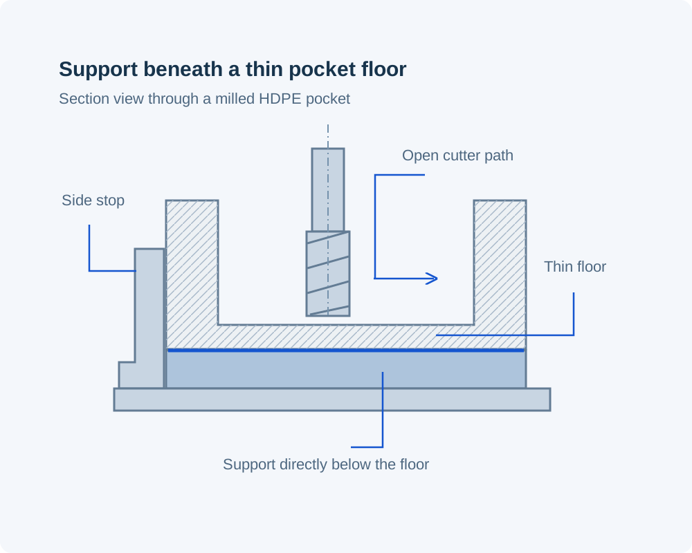
We mill the contact profile and mounting features from the same part datums. Internal corner radii and access to deep recesses determine the cutter path; a recessed fastener must remain below the working surface.
We turn the bore, outside diameter and shoulders that locate a sleeve or roller. A drawing can distinguish a clearance bore from a locating diameter instead of applying the same fit requirement to every surface.
HDPE can deflect under clamping and cutting forces. Broad support and controlled clamping reduce impressions; removing a deep pocket from one side also requires attention to the stresses left in the blank.[3]
| Feature | Drawing requirement | Acceptance condition | Verification |
|---|---|---|---|
| Guide channel | Width, depth and locating datums | Supported as specified | Profile and mounting-location check |
| Sleeve or roller | Bore, diameter and shoulder length | Free state or defined installed fit | Dimensional measurement |
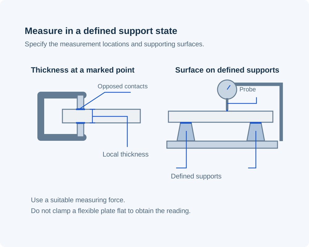
| Flat pad or plate | Thickness and flatness | Defined support; no forced flattening | Thickness and surface measurements |
| Recessed fastener | Hole position and head clearance | Specified screw and mounted stack | Recess-depth and assembly check |
Drawing dimensions use the stated units and feature limits. The accepted support, mounting and temperature conditions remain attached to the measurements.
A close locating bore, a clearance hole and an outside edge serve different purposes. We assess their drawing limits separately, including the section thickness and the condition in which each is measured.
A fixed locating point and appropriately designed slotted mounts can allow a guide to expand along its length. The drawing must still prevent unwanted movement across the travel path.
A thin floor beneath a pocket needs support if its shape controls the assembly. The backing surface and accessible clamping areas are part of the fixture geometry, not details to leave until inspection.
A small screw head can concentrate load in a soft contact area. A wider bearing surface or a drawing-defined sleeve can distribute or limit compression where the assembly requires it.[3]
A separate wear strip or pad lets the working surface be renewed without replacing the support. Its thickness, locating features and fastener recesses must remain compatible with the retained hardware.
Channels and side guides direct a moving item. We machine the path, lead-in and mounting geometry; speed, abrasion and the item’s contact surface determine whether the selected HDPE grade suits the duty.
Nests and support blocks hold a component on defined contacts. Relief pockets leave fragile features clear, and open access lets the workpiece be lifted out without dragging across the fixture.
HDPE can be considered for parts exposed to water or compatible process chemicals. The chemical identity, concentration and exposure temperature belong in the material decision.
Pads can separate a handled item from a metal support. Their profile, retained thickness and mounting access determine replacement fit; surface marking is evaluated against the actual handled item.
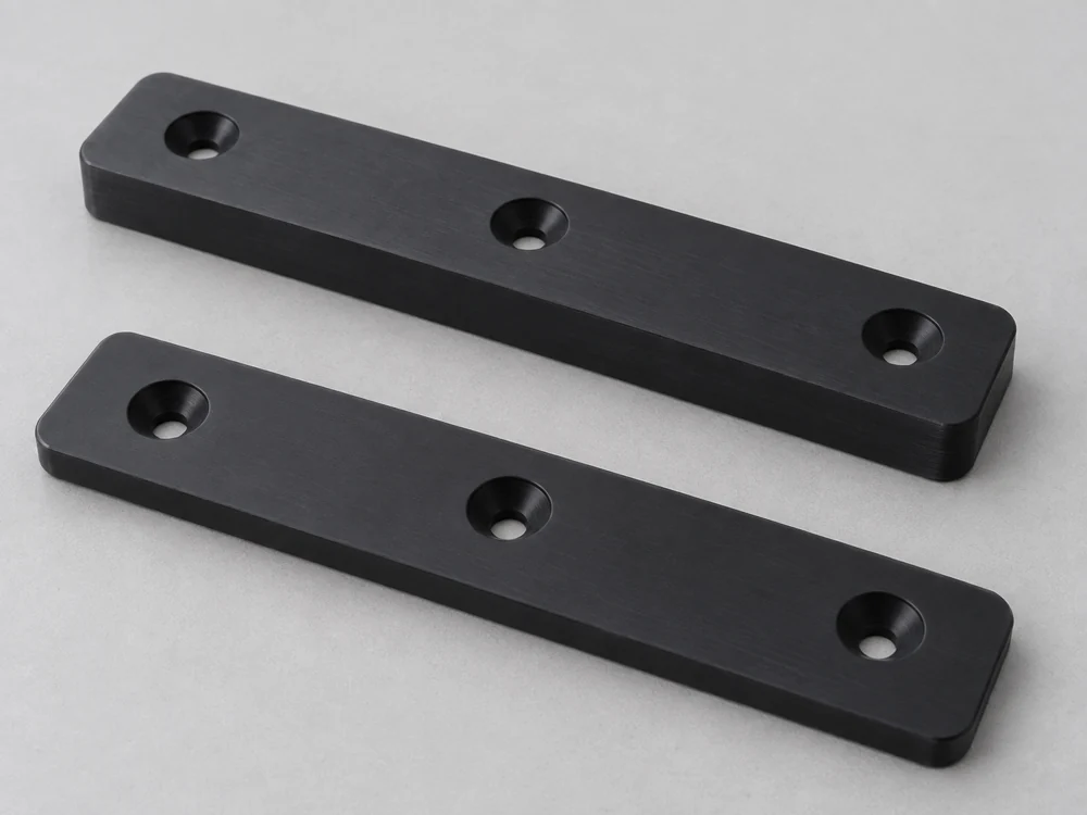
Normal tool paths remain visible on an as-machined face. A cosmetic face and a sliding contact can need different acceptance criteria even when both are on the same part.
Loose burrs and sharp feathered edges can interfere with a guide. We follow the specified edge break while retaining any corner or lip that locates the mating part.
Counterbore depth and pad thickness establish how far a screw head sits below the working face. The drawing can include the remaining contact thickness required before replacement.
Part numbers and revision marks belong on an accessible non-contact area. Packaging protects the finished profile from dents and debris that could affect its next assembly.
The order identifies the HDPE grade, color and required stock records. A supplier’s general resin name is not a substitute for the specified stock designation.
A report identifies the checked features and drawing revision. For a flexible guide or plate, the recorded support condition makes the result useful when the part reaches your assembly bench.
Dimensional checks establish the machined geometry. Wear, chemical exposure and marking trials answer different questions and need their own service conditions and acceptance criteria.
A deep nest cut from thick plate removes more stock than a shallow pad. Choosing the nearest suitable blank reduces waste without changing the finished geometry.
Side holes, underside recesses and narrow deep channels can require additional setups or tool reach. Features accessible from one face are usually simpler to arrange together.
Large thin plates and closely controlled mating features can need extra support and checking. The quote must include the same free-state or mounted acceptance condition used on the drawing.
A batch can share setup work; several different pocket profiles cannot be priced as one repeated part. Group quantities by part number and revision when comparing a first run with repeat supply.
We resolve the stock designation, contact features and open drawing questions before the machining route is released.
An initial component can be checked in its intended support and mounting hardware. Changes to the clearance or contact profile become a drawing revision.
We use the approved part definition for the batch, including its material identity and specified inspection conditions.
Repeat orders reference the approved revision. A changed guide profile, stock grade or fastener arrangement is identified before parts are mixed with earlier deliveries.
Treat recycled HDPE as a separately specified stock grade. The order needs its permitted recycled content and the properties required for the part; the PE300 natural values on this page cannot be transferred to an unidentified recycled sheet. A change from virgin to recycled stock needs material approval before it becomes repeat-production stock.
A worn guide can show the mounting arrangement, but its contact profile may no longer represent the intended size. We need the original dimensions or an agreed reconstruction that distinguishes wear from design clearance. A mating item or unworn matching part can help resolve that difference.
No. Use a named stock grade with documentation covering the intended food, contact time and temperature. Additives and color are part of that material definition. A general HDPE designation or a white appearance does not establish that the finished component meets the application’s requirements.
Only when it covers the actual cleaner, concentration, temperature and duration. Repeated cleaning and simultaneous mechanical load can differ from the source test. For a critical contact part, use the supplier’s grade-specific guidance and an application test that represents the cleaning cycle.
No. The listed yield value comes from a short-term tensile test. It does not define long-term deformation of a loaded spacer or clamped plate. Sustained load, contact area, temperature and allowed movement must be considered in the component design.
Not automatically. The starting stock, amount of material removed and sensitivity to shape change determine whether an additional stabilization step is useful. If one is required, its material-specific cycle and machining allowance need to be defined; copying a cycle from another plastic can change the part unexpectedly.
A reversible strip needs both contact faces and the mounting arrangement defined for reversal. A one-sided fastener recess may leave the screw head exposed after the strip is flipped, while the back face must still seat against its support. We machine the two-face geometry when it is specified on the drawing; an ordinary one-sided wear pad is not assumed to be reversible.
Share your HDPE component drawing, stock grade and quantity. We will review the machining and fit requirements with you.
Technical background for stock selection and HDPE component requirements.
