Solid Base Plates
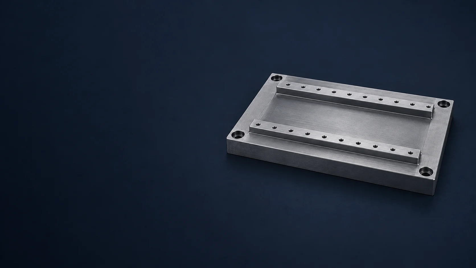
Flat or pocketed plates for tooling, inspection fixtures and equipment mounting. Bolt patterns, clearance openings and recessed areas follow the attached components.
VETCNC · Custom Components
CNC-machined plates and prepared-base interfaces
We machine base plates, stepped mounting bases and the specified faces of prepared cast or fabricated bases to your drawing. Our scope covers the mounting surfaces, locating features and hole patterns that connect your equipment.
Choose the component that matches your assembly. We quote the machined part or defined machining work; blank fabrication and sourcing are separate items in the quotation.
Flat or pocketed plates for tooling, inspection fixtures and equipment mounting. Bolt patterns, clearance openings and recessed areas follow the attached components.
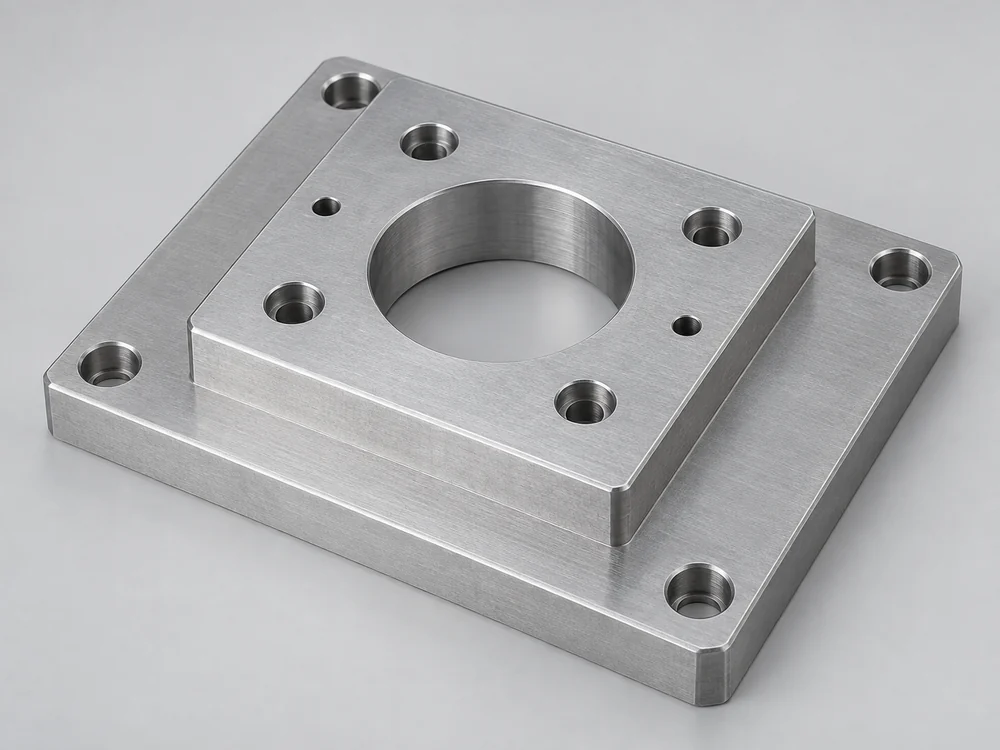
Raised pads and shoulders place motors, bearing housings or guide assemblies at the required height. The connecting faces can be machined as features of one component.
Finish machining of mounting pads, rail seats, bores and holes on an existing blank. The incoming condition and available machining allowance define the work before the final surfaces are cut.
Where a rail is located against a reference shoulder, shoulder height, corner relief and perpendicularity must match the selected guide. An oversized inside radius can prevent the rail from seating.
The pad height and locating geometry establish the position of a motor or bearing housing. Clearance holes provide room for fasteners; dowel holes or a locating bore define position where the assembly requires it.
We work from the specified material grade and delivery condition. The blank form affects how much stock must be removed and where the base can be supported during machining.
For plate-based mounting designs with machined faces, slots and tapped holes. Plate condition and any specified treatment are part of the starting-material requirement.
Explore Steel PlateFor equipment plates where component mass is a design consideration. Alloy, temper, plate thickness and the remaining section after pocketing belong in the specification.
Explore Aluminum PlateFor a base with ribs, bosses or other near-net features. The casting drawing establishes the stock available around the finished pads and bores.
Explore Prepared CastingsA single overall size does not define a machine base. The drawing needs to relate the working interfaces to common datums and identify the surfaces that remain unmachined.
| Feature | Drawing parameters | Assembly reference |
|---|---|---|
| Overall blank | L × W × H (mm or in); mass (kg or lb) | Blank and finished envelopes |
| Mounting pads | Height; flatness; pad-to-pad relationship | Common mounting plane |
| Paired rail seats | Height relationship; parallelism; spacing | Common datums across both seats |
| Reference shoulders | Height; corner relief; perpendicularity | Selected guide geometry |
| Holes and bores | Diameter or thread callout; depth; position | Datum scheme and mating hardware |
| Support condition | Support locations; free or restrained state | Specified measurement setup |
Tolerances apply to the defined feature and span. We quote the accepted dimensions and inspection scope for your base.
We quote face milling, pockets, bores and hole patterns from the part drawing. Features on the underside or adjacent faces determine additional setups and the references needed between them.
Paint or other specified protection must leave the required mounting contact and thread fit intact. Masking identifies the functional faces that remain uncoated and the dimensions accepted after finishing.
The delivery specification identifies contact areas, exposed edges and bores that need protection. Handling and packing arrangements must suit the base mass and the supports allowed by the design.
We tie the inspection scope to the features that locate the equipment. The quotation identifies the dimensional records included with the base.
Local thickness readings do not establish flatness across a plate or the relationship between separated pads. The inspection plan defines the area covered, the common reference and the support condition used for acceptance.
The inspection record relates locating-hole position to the drawing datums and identifies the final surface condition. Measurements taken before finishing must remain distinct from final acceptance results.
We can quote a replacement to a drawing or agreed specification. Worn parts and photographs can help identify the interfaces, but they do not establish the original material, tolerances or hidden mounting dimensions.
Yes. Mark the revised holes, slots or locating features on the drawing and include the mating component details. Changes to support geometry, plate thickness or load paths need approval by the equipment designer.
The base-machining scope does not include purchased motion hardware or equipment assembly. Any additional supply or assembly work must be listed separately in the quotation.
Blank size and condition, stock removal, the number of setups, interface tolerances and inspection coverage determine the work involved. Quantity, finishing and transport complete the quotation scope. We confirm the schedule for that order.
Send the drawing, material, quantity and delivery location. For a prepared base, include the blank dimensions, mass and current condition so we can quote the required machining.