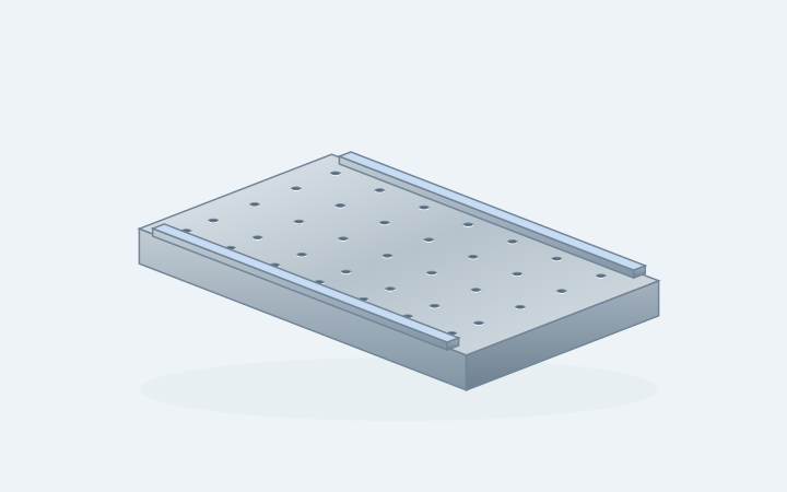
Tooling plates and mounting bases
Flat mounting faces, hole patterns and separate locating pads. Include the plate thickness, support condition and the span over which flatness matters.
Discuss a similar part →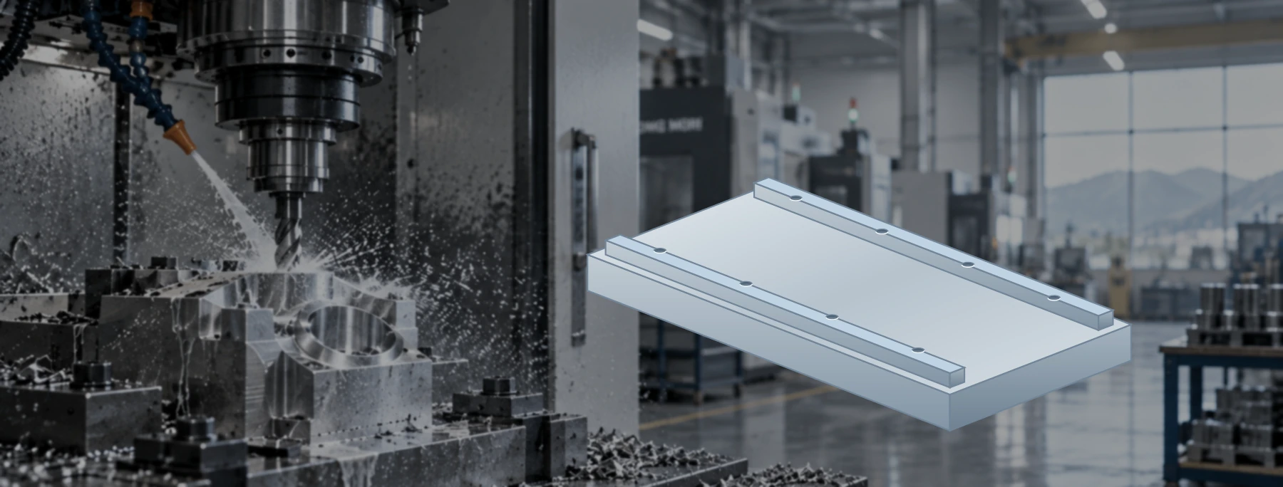
We quote large-part milling, turning and bore machining for plates, housings, rings, shafts and prepared equipment bases. The proposal identifies the manufacturing site, any partner operations, the inspection scope and delivery responsibility; blank sourcing is listed separately.
Flat mounting faces, hole patterns and separate locating pads. Include the plate thickness, support condition and the span over which flatness matters.
Discuss a similar part →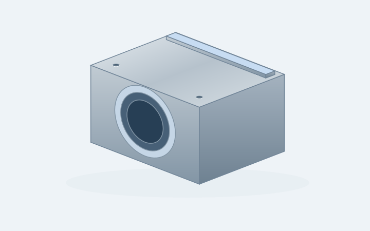
Bores and mounting faces may sit far apart or on different sides. Show which features share a datum and how the component fits into the assembly.
Discuss a similar part →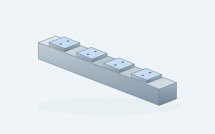
Long blanks need room for workholding as well as travel along the part. Identify the guide faces, hole locations and any sections that can be used for support.
Discuss a similar part →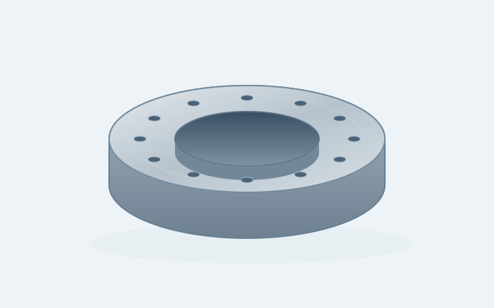
Outside diameter, bore size, thickness and raw-blank weight help establish the turning route. Add bolt-hole and sealing-face details for any later milling.
Discuss a similar part →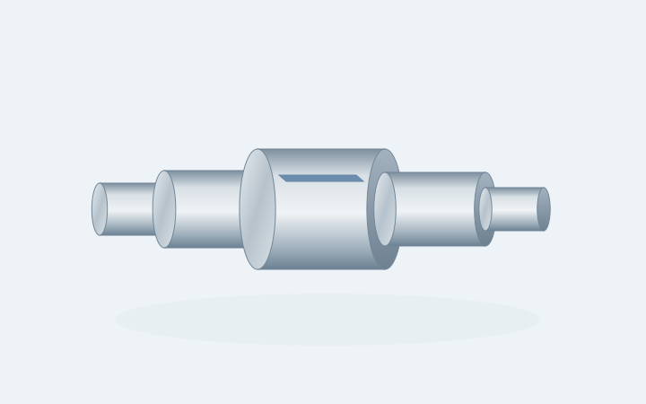
Bearing seats, shoulders and cross-features need to stay related through each setup. Include the starting diameter, total length and the surfaces available for support.
Discuss a similar part →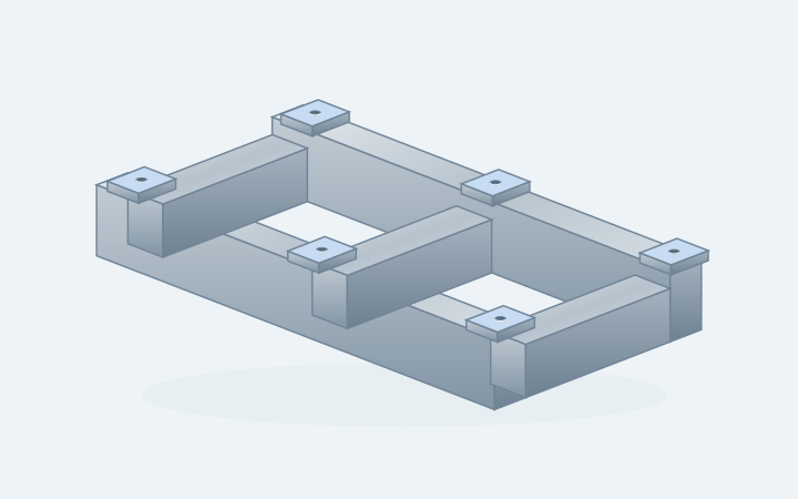
Finish-machined pads and holes can start from a supplied casting or fabrication. Keep the blank specification separate from the final machining drawing.
Discuss a similar part →Try a feature such as a bore, shaft or mounting face, or send your own drawing.
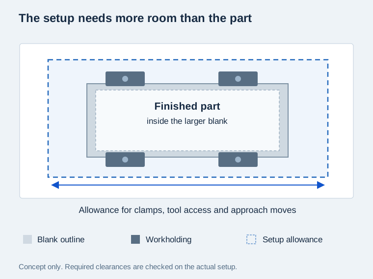
The starting blank includes casting allowance, excess stock and temporary tabs. Its largest dimensions, together with the machined faces, establish the space needed before clamps and tools are added.
The fixture and tool need space too. Machine travel, spindle clearance and table size are separate checks; none should be substituted for the finished part dimensions. [1]
Discuss this optionThe load review includes the raw blank, fixture and any offset mass. Support locations must suit heavy sections and fragile projections in each machining orientation.
A large work area can still have a limiting load or rotary swing. Ask for the proposed setup to be checked against its actual configuration, including any indexed position. [2]
Discuss this optionA drawing may fit inside the machine travel while a long boring bar, holder or angled approach does not. Section views help explain deep features. A marked model can show which areas must remain accessible.
Underside work and features sharing a datum carry through the setup plan. Each orientation needs its own clearance and reference check. [1]
Discuss this option| Item | Part information | Review before production |
|---|---|---|
| Size and travel | Final and blank dimensions, units, machined faces | Usable clearance with fixtures and tools |
| Mass and support | Blank mass, support and handling drawing | Load, distribution, orientation |
| Loading | Blank form, packaged size, site access | Transfer route and handling responsibility |
| Measurement | Features, datums, tolerances, support condition | Access, measurement method, report |
Mounting planes, pockets and hole patterns can require gantry, bridge or horizontal access. The part geometry determines the useful approach; the machine type is selected after size, load and fixture clearance are reviewed. [1] [2]
CNC milling services →Round parts need a review of swing, diameter, length and support. A large flange and a long shaft present different holding problems. Include any flats, keyways or bolt circles that need a second process.
CNC turning services →For a housing, the bore diameter is only part of the job. A section view should show the controlled length, shoulders and nearby faces. Mark any paired bores or mounting features that need a shared datum.
Explore milled components →Specify the material designation, delivery condition and stock thickness. Identify broad faces or thin sections that need particular attention as material is removed.
Aluminum machining →Provide the casting drawing with the machining drawing. Mark locating areas and machining allowance; agree how a shortage of stock or an exposed casting defect will be handled.
Cast iron machining →Include the blank drawing, material certificate requirements and supplied condition. For shafts and rings, show the stock left on diameters, bores and end faces.
Steel machining →State whether you are supplying the finished fabrication or asking for sourcing coordination. Provide its current inspection and treatment records. Welding, heat treatment and finish machining need clearly assigned scopes.
Blank sourcing can be discussed separately. A machining inquiry does not include foundry work, forging, welding or heat treatment unless those items are accepted in the quotation.
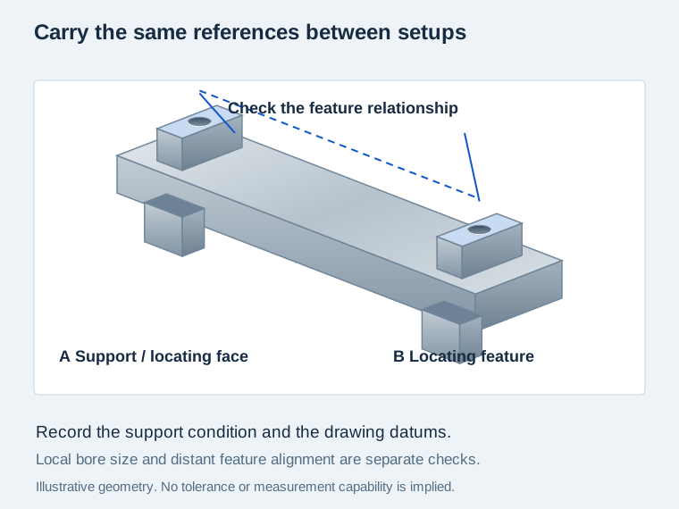
Identify the relationship between separated bearing bores and the mounting face, including the datums used to inspect them. Correct bore diameters alone do not establish alignment.
For a part that is repositioned, identify the references used again in the next setup. Temporary locating features may help, but they need to be planned before the final faces are completed.
For long or flexible sections, agree how the part is supported during machining and measurement. Clamping and support can influence the cut, particularly where the remaining section is less rigid. [3]
Discuss this optionShare the known blank mass, dimensions and any approved handling information. The manufacturing site must confirm how it will receive, position and turn the part before accepting the work.
A part may need to leave the machine for another setup, finishing or inspection. Agree who handles those transfers and how reference faces and exposed edges will be protected.
Identify areas that can support the packed part and surfaces that must not contact the crate. Include destination and unloading restrictions when requesting a shipping scope.
For a large plate, a local thickness check and flatness across the full mounting face answer different questions. For a housing, bore size and bore alignment need separate results. Name the features to be reported and the drawing references used for each result.
Discuss a suitable measuring method before the last cut. Include the agreed support and temperature conditions where they affect acceptance, and separate in-process checks from the final inspection record.
| Feature | Drawing requirements | Inspection considerations |
|---|---|---|
| Broad faces | Flatness, parallelism, controlled area | Support condition; full-face coverage |
| Distant holes | Position, alignment, datums | Common coordinate reference |
| Large bores and journals | Diameter, length, roundness | Measurement access along the controlled length |
| Long rails and bases | Straightness, mounting pads | Free/supported condition; span and measurement locations |
| Coated interfaces | Masking, final dimensions | Checks after treatment; revision and process records |
Mark corrosion-protection areas, cosmetic faces and functional surfaces separately. Keep coating thickness, masking and dimensions after treatment together in the drawing package.
Request the material and treatment records required for the job. Link any dimensional report to the part number, drawing revision and the stage at which the measurements were taken.
Specify any edge-break requirements and protected contact surfaces. Discuss suitable corrosion protection and packaging without leaving residue on surfaces that must later seal, bond or make electrical contact.
Send the drawing, model, material, blank dimensions, weight and quantity. Mark any missing information so it can be resolved before a quote is agreed.
We identify the proposed machining site and the responsibilities for blank supply, specialist processing and inspection. The arrangement can be coordinated through VETCNC or made as a direct partner introduction.
Set the first-part reporting scope and any customer hold points. For repeat orders, keep the approved drawing and setup records tied to the correct revision.
Complete the agreed final checks, identify the delivery lot and confirm packaging, transport and handover responsibilities.
A near-net casting and a solid plate can start from very different shapes. Ask which blank, stock allowance and preparation work the price covers.
A second orientation adds handling and locating work. Deep bores, hard-to-reach features and temporary fixtures can change the proposed route even when the outside dimensions stay the same.
Full-span measurement, treatment records, protective packing and transport may be separate items. Compare quotations against the same drawing revision and delivery scope.
Read the quote-comparison guide →The term describes components that need a larger working space, greater load capacity or a more involved handling arrangement than an ordinary small-part setup. It is not a standard size class. Give the actual dimensions and weight so the discussion starts with your part rather than a label.
We confirm the accepted blank envelope and mass against the proposed manufacturing site and setup, including fixture load, tool clearance and measuring access. The quotation records the accepted dimensions and machining scope for that part.
No. Clamps, fixtures, toolholders and approach moves also need room. A part can fit on a table while a required edge or side hole is inaccessible. Loading clearance and the chosen orientation are part of the same review. [1]
A flange may combine turned faces with a milled bolt pattern; a shaft may combine journals with a keyway. We quote the required operations together, with the reference transfer, support and manufacturing site identified for the component.
Customer-supplied blanks can be reviewed. Send the blank drawing, current condition, material records and available machining allowance. Agree who handles shortages, damage or defects found before or during machining. Sourcing a blank is a separate scope to confirm.
Send the actual dimension and geometric requirements, including any general tolerances referenced on the drawing. A short bore and a long mounting face need different checks. Capability is confirmed against the material, span, support condition, finishing and selected measurement method.
Define the common datums and required relationship first. Then agree the instrument or measuring method, the area or locations covered, and the support condition. The report should distinguish local sizes from alignment or geometry across the component.
Do not assume the same treatment applies to every blank. Provide the material, manufacturing history and any treatment required by the drawing. If a treatment or an intermediate hold point is needed, its specification, supplier and position in the process must be agreed before final machining.
Send the quantity actually needed, plus any later forecast separately. One-off work may need a dedicated setup and full first-part review. Repeat orders can refer to approved fixtures and records, provided the drawing and supply scope have not changed.
Include a dimensioned drawing and matching model, material and blank condition, finished and raw dimensions, blank mass, quantity, critical features and delivery location. Add handling restrictions and the required inspection records. The CNC machining RFQ checklist covers the rest of the file package.
Send the information you already have. A marked-up drawing is useful for showing which faces, bores or mounting pads make the job demanding.
Open items can stay open in the first inquiry. Tell us what still needs a decision instead of guessing a material, mass or tolerance.
Kevin’s role is to keep the manufacturing route clear: who machines the part, who supplies or treats the blank, and who is responsible for the final records. Meet VETCNC.
Use the main contact page →Only share information you are authorized to send. We will use it to respond to this inquiry.
Share your drawing, material and quantity. Tell us what you need and we will reply by email.
Technical references for the processes discussed on this page.