Pocketed housings
We mill housings with thin bases and perimeter flanges. Removing a deep pocket can change the blank’s shape, so the stock condition and sequence matter before the cover face receives its final cut.

We mill housings with thin bases and perimeter flanges. Removing a deep pocket can change the blank’s shape, so the stock condition and sequence matter before the cover face receives its final cut.
Our fixture and mounting plates combine milled faces, locating holes and clamping slots.
We machine brackets from a suitable blank with the mounting faces kept in their required relationship. Counterbores and tool clearance are planned around the surfaces that actually contact the equipment.
We turn spacers with a defined bore, flange thickness and shoulder length. The accepted dimensions identify the finished condition, including any coating on the bore or clamped faces.
We turn adapters that connect different diameters or threaded interfaces. Concentric features, thread runout and shoulder contact are dimensioned separately rather than hidden under a general tolerance.
We machine flat contact faces, mounting holes and pocketed features in 6061 blocks for thermal assemblies.
T6 identifies solution heat treatment and artificial aging. It does not identify plate, sheet or extrusion. We retain the product form with the temper because the applicable material limits depend on both. [1]
For a pocketed body or broad mounting plate, we consider stretch-relieved T651 plate. Lower residual stress is useful when substantial material is removed; it does not replace a flatness requirement on the finished component. [1] [2]
T6511 identifies stretch-relieved extruded stock. Round or rectangular bar can suit sleeves, adapters and repeated cross-sections; the machining plan still accounts for stock direction, straightness and the surfaces removed. [1]
We use T651 plate or T6511 extrusion on a T6 drawing only when the drawing and purchasing specification allow that condition, or an approved substitution is recorded. Permission comes from the drawing and purchasing specification, or from a recorded approved substitution.
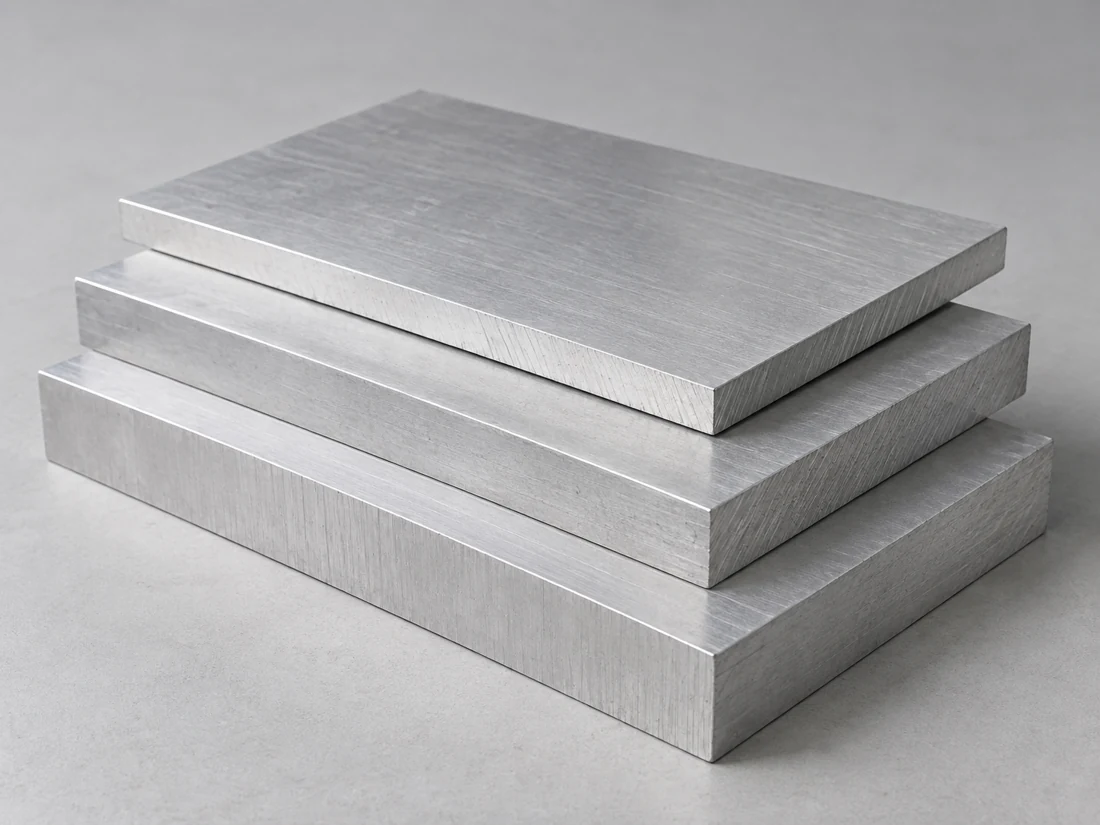
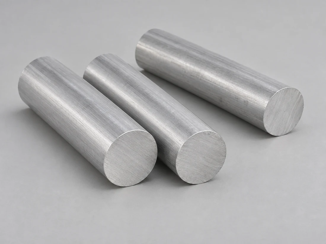
Published stock limits for strength and elongation.
| Stock / original section (in) | Tensile min (ksi) | Yield min (ksi) | Elongation min (%) |
|---|---|---|---|
| T6 / T6511 extrusion, 0.062–0.249 | 38 | 35 | 8 |
| T6 / T6511 extrusion, 0.250 and above | 38 | 35 | 10 |
| T651 plate, 0.250–0.499 | 42 | 35 | 10 |
| T651 plate, 0.500–1.000 | 42 | 35 | 9 |
| T651 plate, 1.001–2.000 | 42 | 35 | 8 |
| T651 plate, 2.001–4.000 | 42 | 35 | 6 |
| T651 plate, 4.001–6.000 | 40 | 35 | 6 |
Sources: Hydro Alloy 6061 extrusions; Kaiser Aluminum Sheet & Plate, Table 7.2 (uncoated T651 plate). Section is the original stock/test section, not the machined wall. Elongation: 2 in or 4 specimen diameters, where a standard specimen can be taken. 1 in = 25.4 mm; 1 ksi ≈ 6.895 MPa.
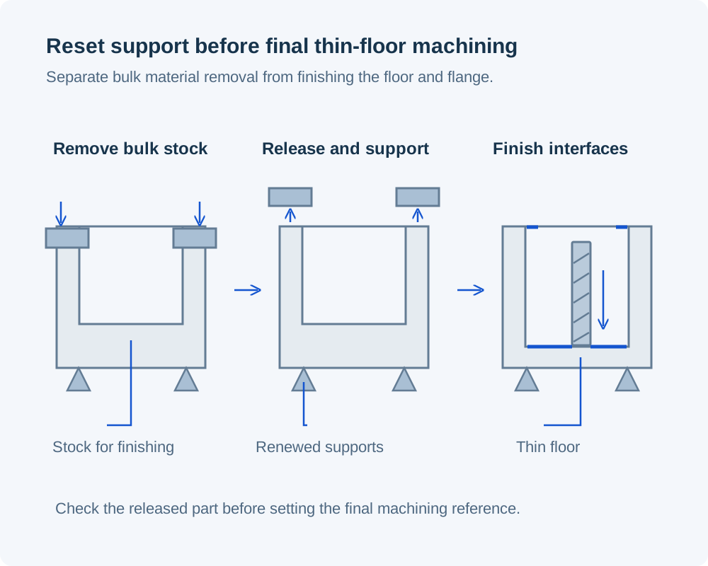
We plan the main stock removal before finishing a thin floor or broad flange. Where the geometry warrants it, the part can be released and its support re-established between roughing and finishing so the final cut is referenced to the current shape.
We choose the bar form around the largest diameter and the length held in the setup. Long chips in 6061 can interfere with a bore or thread, so chip clearance and the sequence of internal and external cuts receive separate attention.
A thin plate clamped flat can move when released. Our process planning distinguishes material movement after stock removal from elastic movement under the fixture, with support arranged around the critical face.[2]
Discuss the finished dimensions in the shared inquiry dialog.
| Feature | Reference parameter | Applies to | Acceptance basis |
|---|---|---|---|
| Locating bore | Ø20 H7: 20.000–20.021 mm | Only a drawing specifying Ø20 H7 | Finished size in the specified coating state |
| Thermally sensitive span | CLTE 23.6 µm/(m·K) | 6061; average over 20–100°C | Drawing temperature and mating materials |
| Type III coated interface | 0.002 in coating → about 0.001 in buildup per surface | AAC 50% penetration / 50% buildup guide | Specified final dimension; actual finish route |
| Broad mounting face | Drawing flatness and datum limits | Defined released or installed condition | Surface measurements with the stated support |
H7 values follow the ELESA+GANTER DIN ISO 286 reference. CLTE comes from Hydro Alloy 6061. The Aluminum Anodizers Council Type III buildup relationship is a planning reference, not a blanket machining allowance. The component drawing controls final acceptance.
We agree which finished dimensions require a recorded inspection result.
We use the available opening and internal radius to establish cutter access. A narrow corner deep inside a housing may need a different tool or an approved relief; increasing pocket depth without changing access adds reach rather than usable space.
We look at where the material remains after machining. A thick rim around a thin floor needs a different support arrangement from a uniformly thick plate, even when both start from the same T651 stock.
We distinguish a directly tapped aluminum thread from a specified insert. Engagement, edge distance and fastener access come from the joint design; an insert adds its own installation geometry and acceptance requirement.
We identify contact lands before specifying the exterior finish. A decorative or insulating coating must not silently extend into a surface intended to transfer heat or carry an electrical connection.
We separate the perimeter flange from the outer cosmetic walls. Hole alignment, seal contact where required and cover clearance belong to that interface, while exterior tool marks follow the appearance specification.
We keep the bore, shoulder and any external thread tied to the same assembly definition. The coating boundary is located so a finished adapter can still engage its mating part.
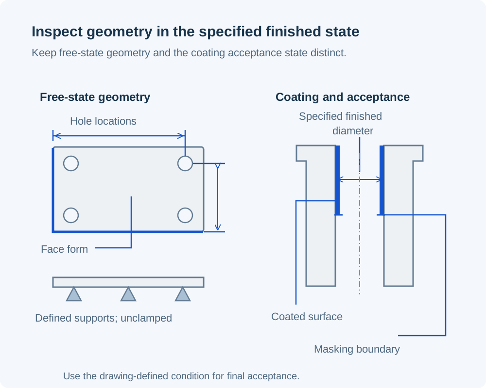
A fixture plate’s working face and locating pattern control how it positions the workpiece. We check those features in the drawing's specified support condition, which is where the finished plate's geometry is accepted.
Contact-face geometry, clamping and the interface layer affect the assembled thermal path. We relate the machined face and fixing features to the mating surface shown on the assembly drawing.
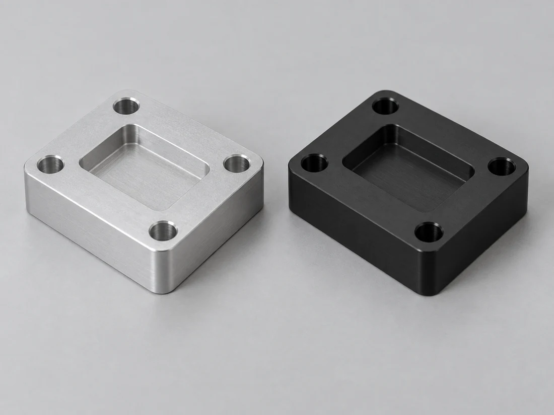
We retain the specified contact geometry and edge condition. Tool-mark appearance is separated from the measured roughness of a bore or mating face.
For a blasted or otherwise prepared exterior, we identify the visible zones and protect functional lands. Surface preparation and the anodizing route are considered together when an appearance sample is required.
We define coated and masked areas before machining final fit surfaces. Thread acceptance, locating bores and contact faces follow the specified delivered condition rather than a single blanket coating allowance.
We keep stock source, surface preparation and finish requirements consistent for parts displayed together. A color name alone is insufficient to define acceptable shade and texture across an assembly.
We retain the material record required by the order against the relevant blank or batch.
We check the mounting face, locating features and fit dimensions using the specified datums and support. Inspection after final treatment is distinguished from the machining checks made before it.
We verify the specified finished condition at masked lands, threaded features and fit surfaces. A material certificate and a coating record serve different purposes; neither replaces the dimensional checks.
A plate blank, round bar and suitable profile leave different amounts of material to remove. We compare the starting shape with the finished envelope while preserving the required product form and temper.
A deep cavity, broad thin face or final machining after treatment can add setups and handling. We account for these operations in the route instead of pricing only the volume of metal removed.
Masked contact lands, an appearance sample and recorded dimensional checks each add a defined task. They belong in the same scope as the machined component.
Programming and initial setup costs are shared across repeat quantities, while material and machining remain part of each component’s cost. A repeatable blank and setup route lets us keep that basis consistent for later batches.
A pocketed housing prototype lets you check cover seating and assembly access before ordering a batch.
When first-part approval is required, we agree which drawing revision, dimensional results and appearance reference establish acceptance for the batch.
We use the approved part revision for batch production. A changed hole pattern or finish specification requires a revised production reference.
A different stock form, temper or treatment can change the basis of an approved part. We check the affected requirements before applying that change to a repeat order.
No. Color and coating type are separate specifications. A black finish may be produced by dyeing an anodic coating, so coating thickness and wear requirements are called out separately from the colour. We retain the required anodizing type and thickness separately from the approved appearance.
A hardness reading measures one property at a test location. It does not by itself establish the alloy chemistry, product form or heat-treatment history. Where material identity is required, we keep the applicable stock record; a separately specified hardness check can add evidence without replacing it.
The region affected by welding can lose strength relative to the original T6 condition. We therefore do not use the incoming T6 stock values as proof of the welded assembly’s strength. The assembly design needs its welding and any subsequent heat-treatment requirements defined separately from machining.
The new cut removes the coating from the machined surface. Before rework, we need to know whether that exposed area is an intended contact land or must regain protection. Any stripping or recoating is considered with the remaining size limits; a reworked dimension leaves the coating thinner or locally removed, so the finish is reassessed.
No. A cast tooling plate is a different material product, even if it is supplied with a flat machined surface. The alloy, strength basis and finishing behavior must satisfy the component specification. We treat that change as a material-selection decision rather than a different brand of T651 plate.
T651 addresses the stock’s stress-relieved condition; it is not a substitute for section stiffness. Kaiser’s 6061 sheet, coil and plate data lists the same typical elastic modulus for T6 and T651. If a finished plate deflects excessively under its working load, the span, thickness and support need to be assessed rather than relying on that temper change alone.
Share the drawing, required 6061 stock condition and quantity. We will define the machining route, finished interfaces and inspection scope for your component.
Published stock limits and finish references support the values above. The component drawing defines its finished acceptance requirements.
We use Google Analytics to see how this site is used. Analytics cookies are set only if you accept. Privacy Policy
