Circular mounting flanges
A ring-shaped flange connects a round housing or component to a mounting face. We machine the center opening, seating face and surrounding attachment pattern as one defined component.
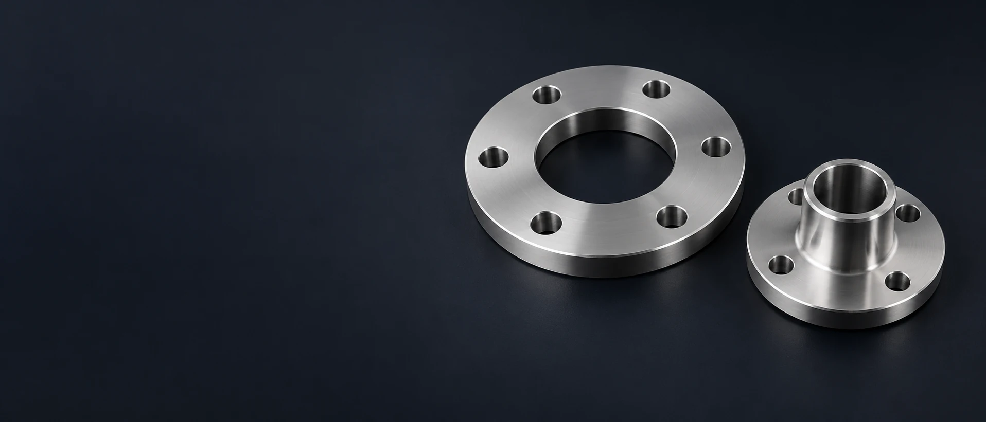
A ring-shaped flange connects a round housing or component to a mounting face. We machine the center opening, seating face and surrounding attachment pattern as one defined component.
A projecting hub combines a shaft interface with the flange’s attachment face. Bore, hub length and flange position locate the connected parts along the common axis.
Adapters connect two mating interfaces with different register diameters or attachment patterns. Their two sides retain the required axial spacing and orientation.
A rectangular outline can fit an equipment footprint while the central opening carries a round mounting interface. Corner and edge holes connect the plate to the surrounding structure.
A radial slit and clamping feature allow the flange hub to close around its selected mating diameter. We machine the released clamp geometry, including its slit and hardware features.
An oval or two-ear profile places the mounting holes on either side of the center opening. This form suits a defined narrow mounting footprint rather than a full circular bolt pattern.
A cylindrical extension carries a register or pass-through bore while the flange attaches from one end. We machine the extension and flange to the specified shared axis and face dimensions.
A solid plate closes the specified housing or access opening. Its fastening pattern, contact annulus and any recess follow the cover-joint design.
No matching flanges. Try another feature name or reset the filters.

Aluminum provides a lower-mass option for mounting rings and adapter plates. We retain the specified alloy and temper so the ordered flange has the intended material condition.

Steel is an option for loaded hubs and mounting interfaces; stainless steel and titanium can be selected where the design calls for their corrosion behavior. Exact grade and condition matter: heat treatment or a change of alloy can change both the manufacturing sequence and the finished joint.

We machine named engineering plastics for spacer flanges, covers and other drawing-defined interfaces. Sustained bolt loading and temperature can change polymer geometry over time, so the design needs a suitable bearing area beneath the fasteners and an appropriate accepted condition.

A male pilot and its mating recess establish radial location. Bolt-clearance holes allow the fasteners to pass; they do not provide the same centering function. The register diameter and engagement depth therefore have separate requirements from the attachment holes.

The hole count, pitch-circle diameter and angular starting position define the attachment pattern. On a two-sided adapter, the relationship between the two patterns determines the orientation of the connected equipment, even when both circles are individually correct.

A seating face sets the axial position of the mating component. A face can be flat yet tilted relative to the bore axis. The drawing’s separate orientation or runout control defines that relationship instead of relying on thickness or flatness alone.
| Feature | Reference or drawing callout | Acceptance focus |
|---|---|---|
| Register bore · unsplit reference | H7, >18–30 mm: lower 0; upper +0.021 mm | Bore limits; mating pilot specified separately |
| Bolt-clearance hole · medium series | M6: Ø6.6 mm; M8: Ø9 mm | ISO 273 clearance diameter, not tapping size |
| Equally spaced six-hole pattern | 360° ÷ 6 = 60° angular pitch | Pitch-circle diameter and first-hole orientation still defined |
| Flange thickness and axial step | Drawing-defined seating-face distances | Installed spacing between actual contact faces |
| Bolt head or washer seat | Selected hardware and seat geometry | Bearing face, recess and corner clearance |
| Face-to-axis geometry | Specified datum axis and orientation/runout control | Face relationship accepted from the defined axis |
H7 deviations apply only when the drawing selects that class in the nominal band >18 through 30 mm. ISO 273 values are selected medium-series clearance holes; special joints follow their own design requirements. The angular value is a geometry calculation. The references describe the published standards; the tolerance, load and pressure figures for your flange come from its released drawing.

We turn the circular profiles, bores and seating faces to their specified relationships. A component with registers on both sides needs a route that carries the defined axis through the workholding and any change of setup.
Milling completes bolt holes, flats, rectangular outlines and access features around the turned geometry. Pattern location is related to the functional register or bore, so an outer edge is not used as an inspection reference unless the drawing assigns that role.
Large openings and clamp slits leave less material supporting the flange. Workholding and the cutting sequence must let the part relax into its specified free condition rather than machining a forced shape that changes when released.[2]
Anodizing or a deposited coating can change the accepted register or bore size. The finish definition separates treated surfaces from masked interfaces and identifies the final dimensions required for the mating part.
A bolt head or washer needs the specified bearing surface. Spotfaces and counterbores provide that surface at the intended depth and leave room for the selected head and assembly tool.
Lead-ins help the pilot or shaft enter without catching a raised edge. We preserve the specified contact face and edge geometry while removing unwanted burrs at the bore, mounting holes and milled openings.
Cosmetic texture applies to the defined visible areas. It can be separated from the register, seating face and hidden recesses so appearance requirements do not unnecessarily extend to every machined surface.
The selected hardware also needs clearance at its head-to-shank fillet so that the head seats against the flange. [3]
We check the specified bore or pilot and the location of its mounting pattern from the drawing datums. Clearance diameter and pattern position are reported as two separate results.
For a specified runout check, the measurement refers to the drawing’s datum axis. Measuring from a convenient outside diameter can establish a different axis and produce a different result. The inspection condition identifies the reference and support used.
Part number, revision and batch identity connect the supplied flange to its specified material, treatment and dimensional records. Our quotation identifies the report and sampling scope.
An initial flange can establish fastener access and available axial space in the mating equipment.
A two-sided adapter connects two equipment interfaces. A revision to either mating component can require a new adapter even when the other side is unchanged; the accepted adapter remains tied to the agreed pair of interface drawings.
Changes resulting from the first installation become the controlled component revision. The production batch follows that accepted geometry rather than an uncorrected trial drawing.
Packing keeps hard edges away from the register and seating face. Long hub extensions receive support without loading the thin flange as a cantilever during transit.
Starting stock diameter, the amount removed around a narrow hub, work on both faces and secondary hole patterns affect machining time. Thin rings and interrupted profiles can add support work. Larger batches spread programming and fixture preparation across more parts; material removal and finishing remain per-part operations.
| Include | Required detail |
|---|---|
| Flange geometry | Model/drawing, bore or pilot, hub profile, face distances and units |
| Mating interfaces | Register limits, bolt pattern/clocking, datums and face controls |
| Finished condition | Material/condition, coating or masking, hardware seats and acceptance state |
| Order and acceptance | Part/revision, quantity, reports and any separate assembly requirements |
Identify the governing interface drawing where two different equipment patterns meet. Controlled part numbers keep each adapter side and revision traceable.
No. This page covers drawing-defined mechanical mounting flanges and adapters. ASME B16.5-2025 addresses pipe flanges and flanged fittings with requirements for materials, pressure-temperature ratings, dimensions, marking and other matters. Full compliance and a pressure rating follow the specified product standard and its conformity scope. A pressure-piping requirement needs its own specified product and conformity scope.
The defined shaft connection provides the torque path: for example, a key, interference fit or designed clamping interface. Allowable torque comes from the defined shaft connection, the fastener preload and the contact surfaces that carry the duty. Fastener preload, contact surfaces and the selected connection design must support the duty. We machine those specified features without assigning a catalog coupling rating to a custom hub.
A conventional cap-screw joint normally has clearance through the flange being clamped and thread engagement in the mating part; a through-bolt can instead clamp against a nut. Tapping both mating holes changes that arrangement and can prevent the screw from drawing the faces together as intended. Such a joint needs an explicit design rather than treating tapped and clearance holes as interchangeable choices.
Use the condition in which the drawing requires the bore to meet its limit. A free-part bore and one closed around a shaft or mandrel under defined clamping conditions can differ. If acceptance is in the clamped state, define the mating diameter, hardware condition and closure arrangement, and we measure the bore in that state.
A pre-machined flange establishes the geometry before welding. Welding can change face alignment and shape, so a requirement that applies to the welded assembly may need later finish machining or a final check. The manufacturing sequence separates those stages. Our quotation identifies whether the supplied flange is finished for installation or left with an agreed machining allowance for a later operation.
No. The actual contact annulus and the load available from the fasteners affect gasket selection. A gasket that matches the hole positions can still have an unsuitable compressed area, material or thickness for the joint. The selected gasket and cover-joint design define the mating surfaces, and sealing performance follows the compressed area, material and thickness they call for.
Send the flange drawing and the mating-interface definition with the material and quantity. We will quote the component machining, specified finished condition and required records.
References for the selected fit, fastening and joint distinctions on this page.
We use Google Analytics to see how this site is used. Analytics cookies are set only if you accept. Privacy Policy
