Cross-drilled distribution blocks
We machine a main gallery with intersecting branches and the access holes used to make them. The body routes fluid between the ports shown on your drawing.
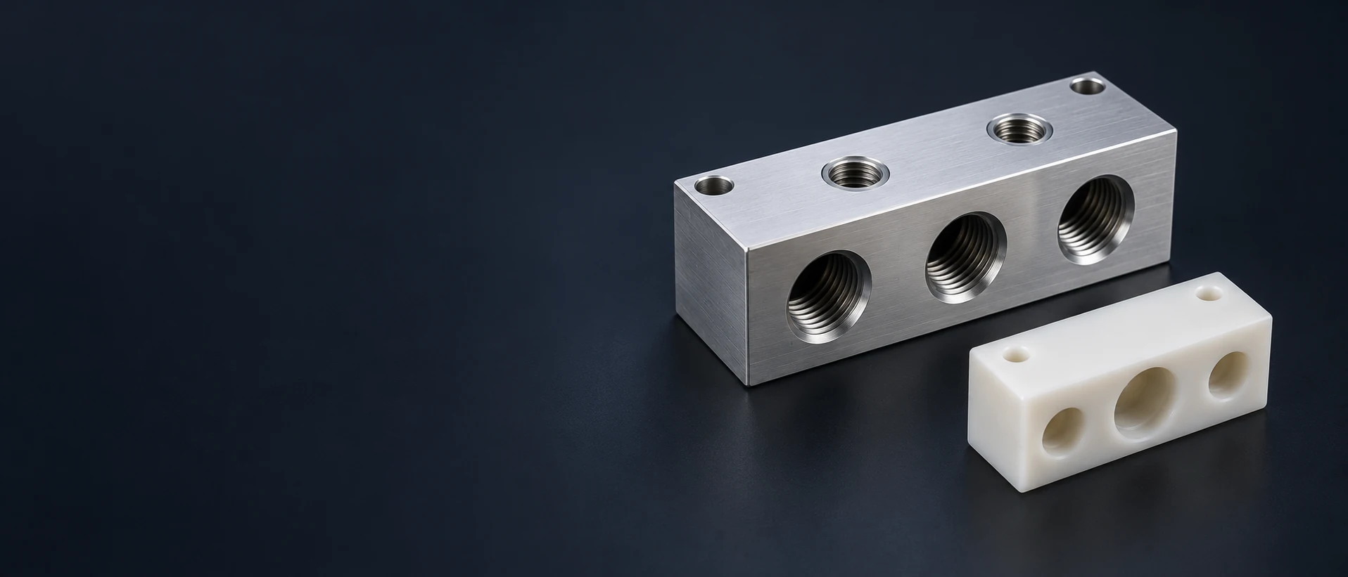
We machine a main gallery with intersecting branches and the access holes used to make them. The body routes fluid between the ports shown on your drawing.
A machined mounting face connects a surface-mounted valve to the block’s supply, return and working passages. The interface includes the face ports and fastening pattern.
Stepped cavities receive the selected screw-in cartridge. We machine the block to its specified cavity drawing, including the internal shoulders and separate passage entries.
Compact bodies connect passages approaching from several directions. Each connection carries its own port designation so an inch, metric or pipe-thread interface remains identifiable.
An elongated gallery supplies a row of branch outlets. Outlet pitch, mounting points and end connections define how the bar fits beside the equipment it serves.
Adapter bodies place different connection interfaces on the required faces. The internal route joins the selected ports without needing the outside fittings to share an axis.
An open milled channel gives access to a route that cannot be drilled as a straight gallery. We supply the drawing-defined body and, where included, its separate cover; joining and assembly have their own scope.
We machine ported bodies in the specified engineering plastic. These parts suit designs that select a polymer wetted path rather than using a metal block interchangeably.
No matching blocks. Try another feature name or reset the filters.

Aluminum reduces block mass and is readily machined into multi-port bodies. The specified alloy and temper remain part of the drawing; the fluid, closures and loaded interfaces determine whether that material suits the design.

Stainless steel is an option when the design specifies a corrosion-resistant metallic wetted path. Steel and brass remain distinct selections for the block and its threaded interfaces; these metals are heavier than aluminum at the same geometry. The named grade and condition govern the supplied material.


The valve-side ports and fixing holes must share the mounting face’s datum system. The seals land over the intended openings because the ports and fixing holes share the mounting face's datum system. Locating features also establish the required valve orientation.

A straight-thread O-ring port uses more than its tapped hole: the lead-in, seal housing and surrounding face are part of the connection. A thread gauge checks the thread; the seat and entry geometry still need their own dimensional acceptance.

Drill axes and depths determine which galleries meet inside the body. A passage that stops short leaves an unintended restriction; one that goes too far can open into another circuit. We use the drawing’s common datums and depth definitions for these cross-face relationships.
| Feature | Reference or drawing callout | Acceptance focus |
|---|---|---|
| Inch SAE O-ring boss port | -4: 7/16–20; -6: 9/16–18 | Selected thread plus complete O-ring port geometry |
| Metric ISO 6149 port | M12×1.5 or M14×1.5 | Metric thread and specified seal housing |
| NPT pipe-thread port | 1/4–18 NPT; 1:16 diameter taper | Tapered thread engagement and specified sealing method |
| Cartridge cavity | Selected cavity identifier and drawing revision | Shoulders, seal leads and passage entry locations |
| Face-mounted valve interface | Specified mounting designation and face requirements | Port pattern, locating features and sealing land |
| Cross-gallery and closure | Specified bore axes, depths and closure position | Required intersections and remaining circuit separation |
Selected interface references from Parker port guides; the full port standard and fitting drawing govern sealing geometry and acceptance. Unified callouts give diameter in inches and threads per inch; metric pitch is in millimetres. The NPT fraction is a nominal pipe size. The references describe the published port standards; the tolerances and pressure rating for your block come from its released drawing.

A drilled gallery follows a straight tool path. Its entry face, depth and intersection with the next bore have to be reachable in the planned setup. A closed curved route needs a different component construction, such as the covered-channel form shown above.
Cartridge cavities combine several diameters, shoulders and seal-entry features. The finishing tool follows the selected cavity profile and locating shoulder. Sun Hydraulics’ cavity guidance also warns that reaming cannot be expected to correct a drilled hole that has wandered off its intended axis.
Burrs at crossing bores can remain inside an otherwise finished block. The route needs access to remove them and clear the passages before closures hide the intersections. A difficult internal edge must be resolved in the machining plan rather than treated as an outside chamfer.[3]
The selected seal interface sets the surface-finish requirement. Keeping a sealing land free of a scratch or edge defect is different from specifying an attractive exterior texture; their acceptance areas remain separate on the part.
External coating and internal treatment are different specifications. Coverage, masking and process access affect whether the specified layer reaches a passage or changes a port’s final dimensions. We quote the required finish areas and final condition.
An expansion-plug bore or threaded closure seat follows the selected closure design. Its accepted diameter and surface condition apply at installation; coating that changes the seating zone cannot be added without accounting for that change.
Markings connect each physical port to the released circuit map. They must remain legible after finishing without damaging a seal zone.
Finish and marking operations must not leave loose residue inside the fluid paths. [3]
Our dimensional scope follows the specified port, mounting-face and cavity features. Sizes, depths and datum relationships are checked against the released drawing in the quoted final condition.
Acceptance must distinguish an intended open connection from an unintended connection between circuits. The port map identifies both. Any required passage verification, cleanliness acceptance or pressure-related testing is defined separately from the dimensional report in the quotation.
Part number, revision and batch identity connect the supplied body to its material, finish and agreed inspection records.

A first body allows your assembly review to establish fitting access, valve clearance and the installed port orientation before release of the repeat component.
The accepted configuration includes hidden galleries, closure positions and valve interfaces. An unchanged exterior model does not authorize a change inside the block.
A different port map needs a controlled part or revision identity. Marking and packing keep similar-looking blocks from being mixed at installation.
Packing protects sealing faces and port entries and keeps loose material out of open passages. Temporary shipping protection remains distinguishable from a specified circuit closure.
The number of machining faces, deep galleries, cartridge cavities and inaccessible intersections drives setup and tooling work. A larger repeat quantity spreads programming and fixture preparation over more bodies; it does not remove the per-part work of making and finishing the internal features.
| Include | Required detail |
|---|---|
| Body model and circuit map | Passage sections, port labels and intended connected or isolated networks |
| Connection and valve interfaces | Port standards, fitting drawings, valve pattern and cavity identifiers/revisions |
| Closure and finished condition | Plug/closure part references and depths; finish areas, masking and supplied assembly state |
| Order and acceptance | Matching part/revision, material/condition, quantity, records and separately specified tests |
Use a controlled drawing or section view for hidden features that a simplified solid model does not fully define. Agree secure file transfer for restricted designs.
No. Safe working pressure comes out of the pressure design for that block. Wall sections, intersecting bores, closures, temperature and the selected connections all affect the design. ISO 6149-1 also makes permissible connection pressure dependent on size, material, design and application. We quote the machined component against the released design rather than assigning a stock pressure rating to every aluminum block.
No. ISO 4401 defines mounting-surface dimensions for four-port directional valves so the interfaces can be interchangeable. It does not choose which passages connect inside your body or which valve function your system needs. The selected mounting designation and the separate internal circuit definition are both needed.
Not necessarily. The thread is only one feature. Shoulder depths, sealing diameters, lead-ins and the locations at which passages enter the cavity can differ. Use the selected cartridge manufacturer's cavity identifier and controlled drawing, since the shoulder depths, sealing diameters and lead-ins are what make the valve seat and operate correctly.
That depends on whether the opening is a manufacturing access hole or a future service point. A permanent expansion plug seals by expanding into its prepared housing; it is not interchangeable with a removable threaded closure. A removable design preserves maintenance access but needs its own sealing and retention geometry. The chosen closure defines the machined seat and its installation requirements.
No. A port label does not describe the smallest internal passage, the path length, turns or installed restrictions. Flow must be considered with the fluid condition and the permitted pressure drop through the complete route. The machining drawing defines the geometry we supply; it does not by itself create a tested flow rating.
A design can contain isolated passage networks, but their separation must be explicit. Crossing drill paths, plug depths and any shared interface need to preserve that isolation. If cross-circuit leakage is an acceptance concern, the component specification must identify that requirement separately from leakage to the outside. The block’s exterior dimensions cannot demonstrate isolation.
Send the released body drawing, port map and interface references with the material and quantity. We will quote the machined component and identify the included finish, records and delivery condition.
Interface definitions and manufacturing references used on this page.
We use Google Analytics to see how this site is used. Analytics cookies are set only if you accept. Privacy Policy
