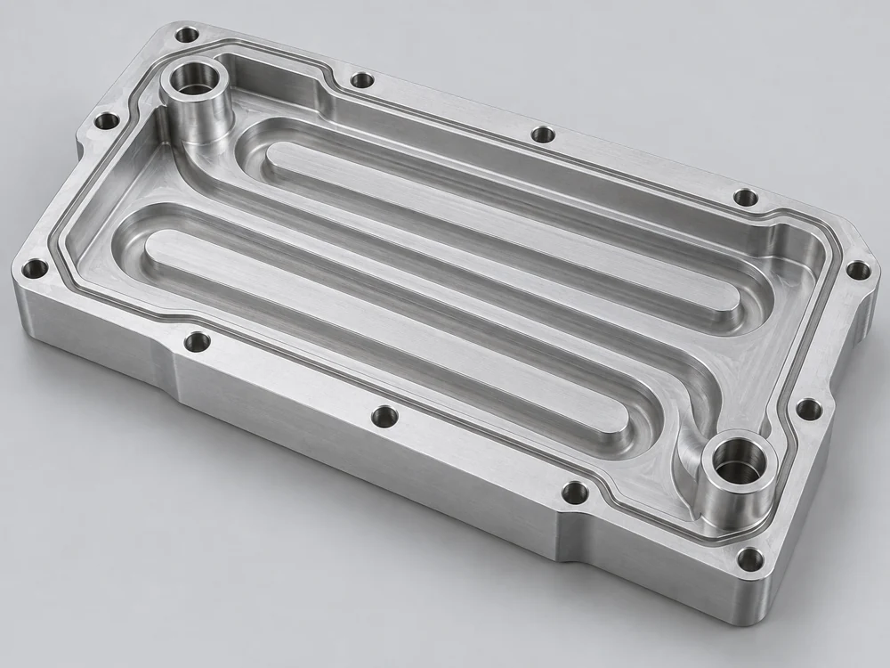
Cold Plate Bodies and Channel Plates
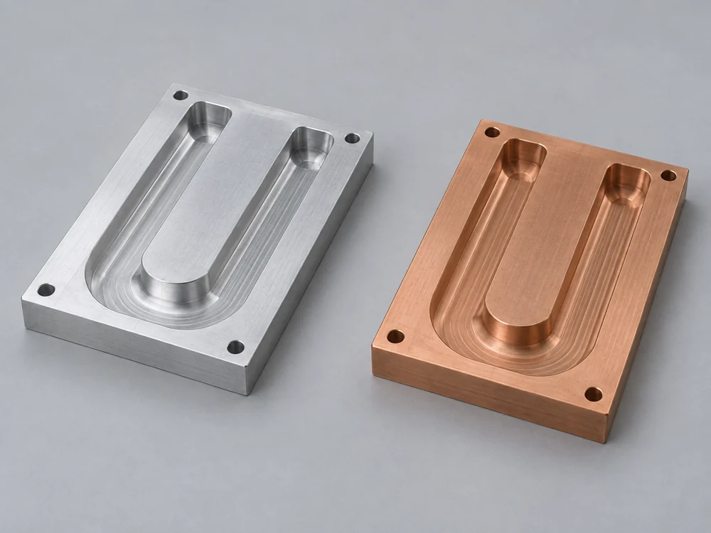
We mill open channels, pockets and the surrounding joint features. Channel depth and the remaining base thickness need separate dimensions so the coolant path and heat-contact base follow the same design.
VETCNC · Custom Components
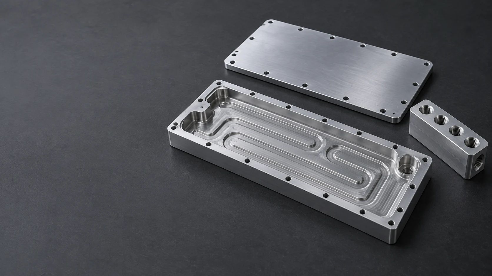
Cold plate bodies, covers and manifolds
We machine liquid cooling components to your drawings, from open-channel bodies and ported covers to manifold blocks and mounting parts. Our scope is component machining for your cooling assembly.
We machine the passages, ports and mating features on individual parts. The released design defines how those parts close, connect and mount within the liquid cooling system.
We mill open channels, pockets and the surrounding joint features. Channel depth and the remaining base thickness need separate dimensions so the coolant path and heat-contact base follow the same design.
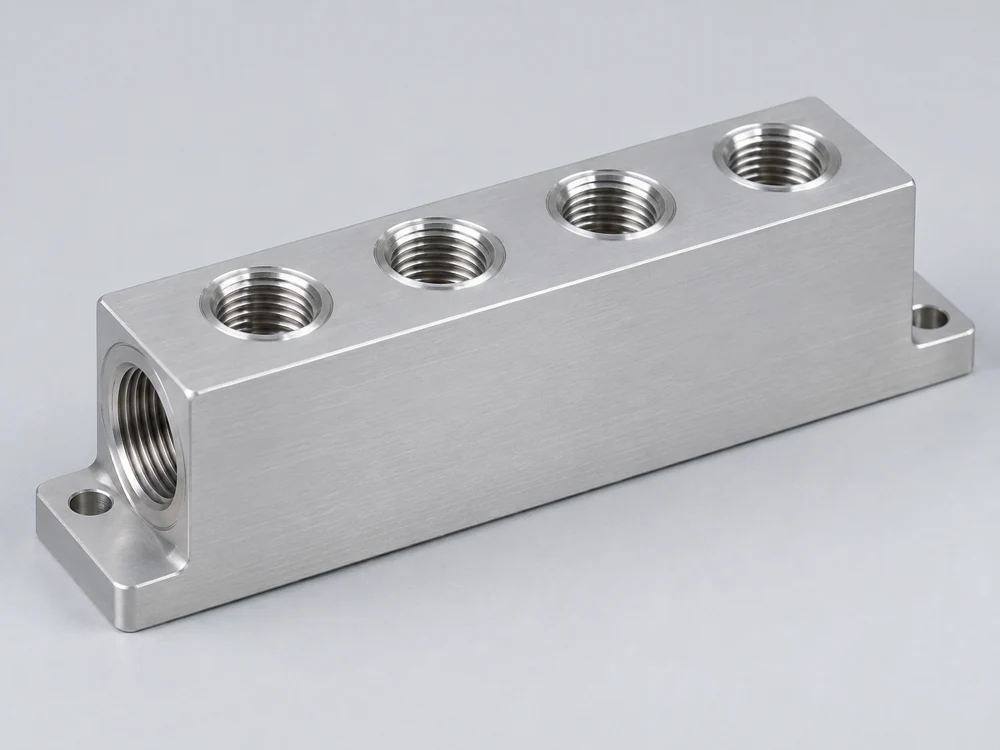
We machine distribution passages, connection ports and mounting holes. Cross-drilled passages need defined end closures; port spacing must leave room for the selected fittings and their installation tools.
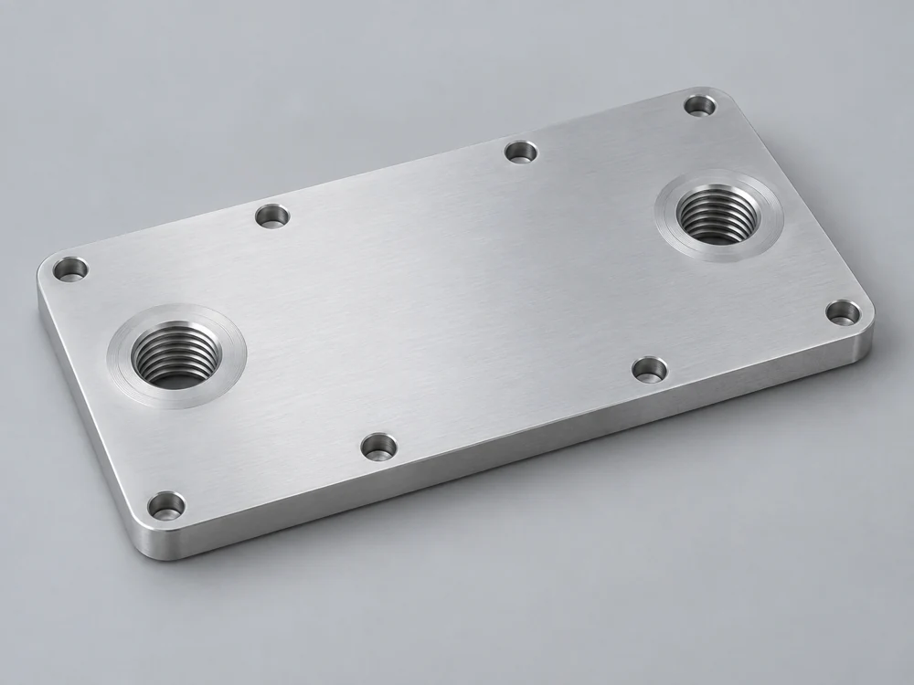
We machine covers with the specified port and fastening pattern, plus separate brackets or spacers. Their locating features keep the coolant connections and cold plate aligned with the surrounding assembly.
A cold plate has two different mating requirements: the cover joint contains coolant, while the opposite face contacts the heat source. We keep their dimensions and surface requirements separate.
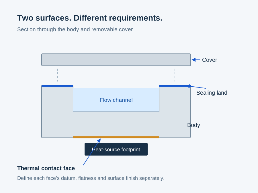
For an O-ring cover, the groove and mating land follow the selected seal design. A cover intended for joining needs its own joint geometry and machining allowance. We machine those features to the drawing.
The contact footprint, face flatness and mounting height set the physical interface with the cooled component. We locate the fastening and datum features from that interface, including clearance for the specified thermal interface material.
We machine the specified alloy and stock condition. The body, manifold and mounting hardware can serve different functions, so they need not use the same material.
A lower-density option for channel bodies, covers and mounting parts. The stock temper and any later joining operation matter when defining the finished component.
Mass, stock condition and the downstream joining route.
ETP copper provides high thermal conductivity for the heat-transfer body. The material data below help compare conduction and mass with 6061 aluminum.
Heat conduction through the body and component mass.
An option when the downstream joining procedure calls for oxygen-free copper. C10200 and C11000 are distinct grades; similar conductivity does not make them interchangeable in that procedure.
The copper grade required by the approved joining procedure.
An option for manifold and connection components in loops that specify 316L wetted parts. Its role is the fluid connection rather than replacing a copper heat-transfer base.
The loop’s approved wetted-material specification.
Copper has higher thermal conductivity; aluminum has lower density. These properties support material selection, while channel geometry, coolant flow and the assembled contact interface determine cold plate performance.
| Material / product condition | Thermal conductivity W/(m·K) | Density g/cm³ |
|---|---|---|
| 6061-T6/T6511 extrusions | 167 at 25°C | ≈2.71 |
| C11000 ETP copper | ≈391 at 20°C | 8.91 at 20°C |
Reference data: Hydro, Alloy 6061 extrusion data sheet (typical conductivity; density temperature not stated), and Copper Development Association, C11000 physical properties. Values apply to the stated material and product condition.
Our quotation covers the individual part numbers and their finished condition. Cold plate thermal design, cover joining, assembly and system qualification are outside this machining scope.
Channel corners must accommodate the specified cutter radius. Cross-drilled passages need access for removing burrs where the bores intersect.
If the drawing calls for a coating, its thickness and coverage affect the seal groove, fitting interface and heat-contact face. We identify the finish and masked areas in the machining quotation.
We identify supplied parts by part number and drawing revision. Packaging separates components and protects sealing lands, contact faces and port edges during shipment.
We link dimensional checks to the drawing’s functional features. A component inspection report records machined geometry; leakage and thermal performance are accepted on the completed cooling assembly.
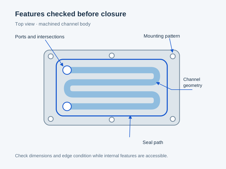
Channel depth, remaining base thickness, groove dimensions and port features each have their own drawing requirements. Thread checks follow the specified fitting interface; a passing thread gauge alone does not verify the sealing land.
We check the specified face and mounting dimensions from the stated datums. The quotation identifies the dimensional records included, so acceptance follows the same features used to locate the part in its assembly.
Not as a direct manufacturing substitution. Skiving and milling produce different channel and fin geometries. A change in fin thickness, spacing or channel shape requires design approval and cooling validation. We quote the released milled geometry rather than treating the two routes as equivalent.
A controlled cover drawing can define the interface for a replacement body. Include the seal section, groove location, fastener pattern and locating features. A used cover may help establish the shape, but wear or distortion should not become the nominal dimensions of the new part.
No. BSPP uses parallel threads with a separate sealing feature; NPT uses tapered threads and its specified sealing method. Matching a nominal port size does not make the interfaces equivalent. We need the selected port standard or fitting drawing, including its seat or spotface.
Only after the material change is approved for that loop. Compatibility depends on the coolant product, its inhibitor package, operating temperature and all wetted metals and seals. A water-glycol label alone is insufficient, and a coating does not automatically qualify the substitution.
Identify the closed assembly being tested, test medium, pressure, stabilization and hold times, temperature, and leakage limit with units. An open machined body cannot demonstrate the completed cover joint’s leak tightness. The assembly test belongs with your joining or assembly scope, separately from our dimensional inspection.
Define the permitted particles or residue and the inspection method for the wetted passages. A visual burr check does not establish a particle-cleanliness limit. If acceptance uses an extraction or flushing test, include that procedure and limit as a separate requirement in the component specification.
Use the stage at which the drawing requires the interface to meet its limit. Heat from joining and loads from assembly can change the face geometry. A pre-joining report establishes the machined condition; it does not replace a final check when the design requires flatness after joining or under specified mounting conditions.
Send the component drawings, material, quantity and required finish. Include the mating cover or fitting details where they define the machined interface.