On this page
Choose a finish for a CNC machined metal part by assigning a job to each surface before naming a process. A visible aluminum cover might need a controlled color, its locating bore must still fit after treatment, and its grounding pad may need a different surface condition. A stainless fitting whose concern is residual free iron has a different finishing task from one whose wetted passage must also be smoother. A steel bracket may need corrosion protection without losing thread fit. The metal grade, operating exposure, functional features and final inspection requirement narrow the viable routes.
“Anodized,” “passivated,” “plated,” “blasted” and “brushed” do not describe interchangeable versions of one result. Some alter the base surface, some deposit material, and some mainly change texture. The selection below starts with those differences and ends with a drawing note that can be produced and checked.
Give each surface one clear job
Start on the part drawing, not in a finish catalog. Mark the faces that locate, seal, conduct electricity, carry load or slide against another part. Mark the faces that customers see and the faces exposed to moisture, chemicals or handling. One face may have several jobs; a sealing land may also be visible. The important point is that the jobs are explicit. Otherwise “finish all over” can coat a fit or leave an unprotected corner where the designer expected protection.
These are parallel questions to answer for each zone:
- Fit or motion: Will any added film, oxide growth or metal removal change a bore, shaft, thread or bearing seat?
- Contact or sealing: Does this surface need a defined roughness, cleanliness, electrical path or gasket contact condition?
- Exposure: What liquid, atmosphere, abrasion or handling will the finished part actually see?
- Appearance: Which faces need a controlled color, gloss or grain, and what variation is acceptable?
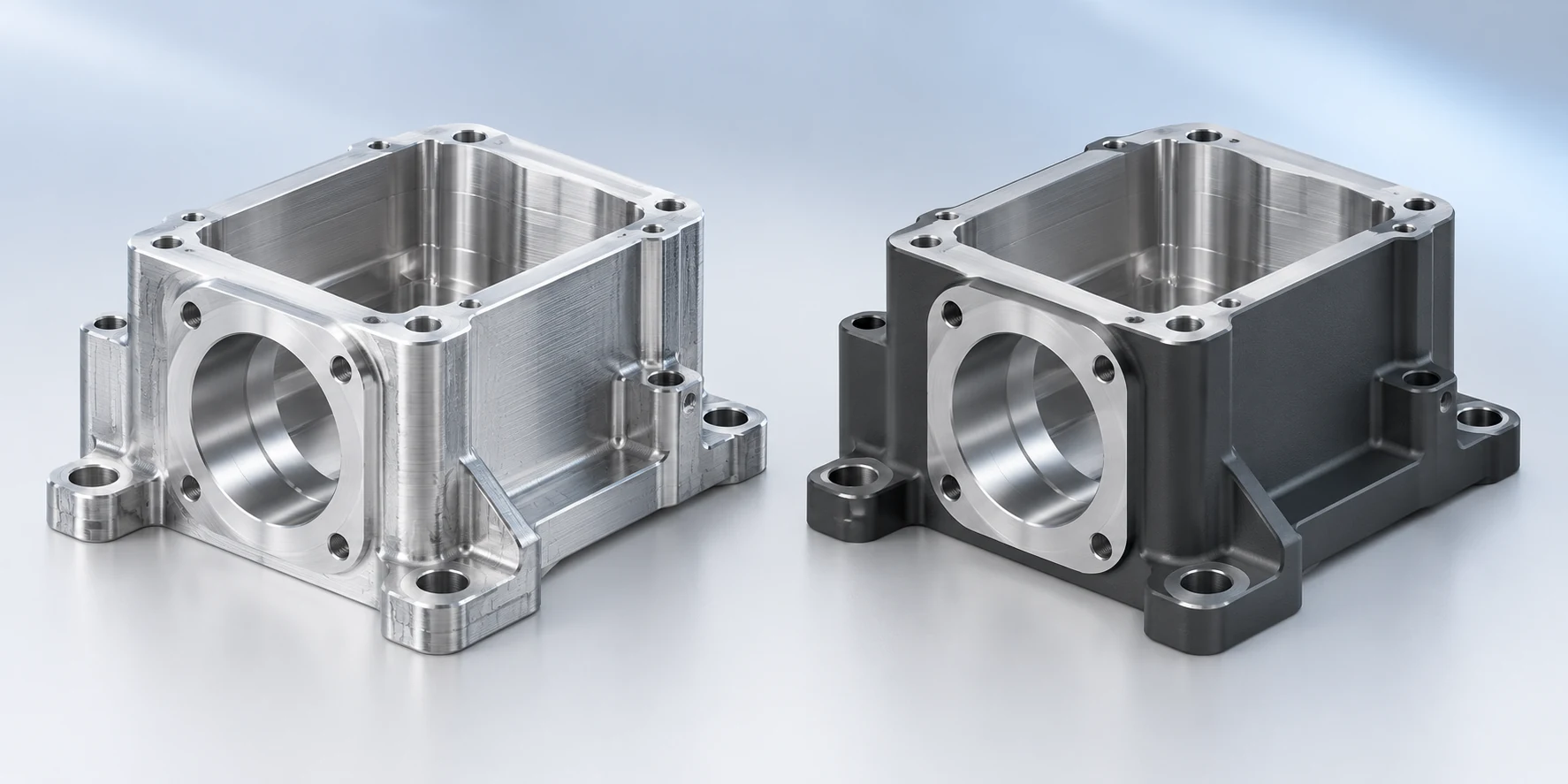
A freshly milled surface is not necessarily a failed surface. If its texture, edges and condition meet the part’s requirements, an extra decorative operation may add cost and a new fit risk without improving the function. Conversely, a smooth-looking face is not proof of corrosion resistance. A visual process such as brushing or blasting primarily addresses texture and preparation; a specified anodic oxide, metallic deposit or chemical treatment has a different purpose. This distinction is visible in the process descriptions of the Aluminum Anodizers Council and ASTM’s stainless and zinc standards. [1] [2] [3]
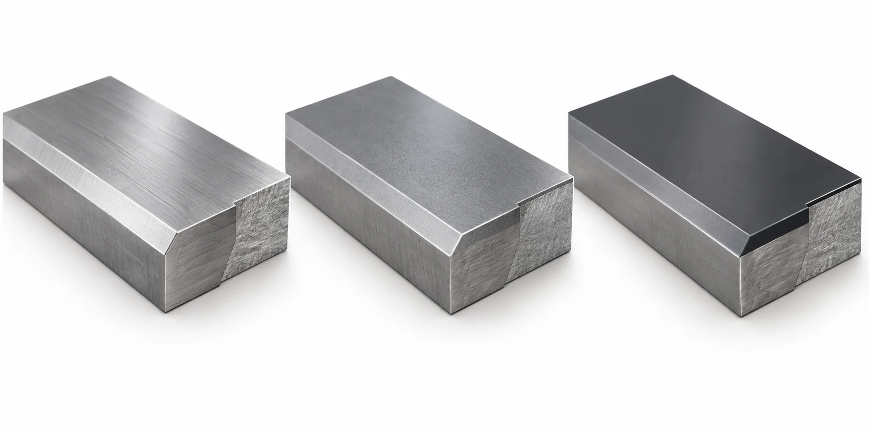
Keep texture and dimensions separate in the drawing. A roughness value describes a measured aspect of surface texture, not size, flatness or a complete corrosion system. A cosmetic sample can control what a face should look like, but it cannot substitute for a bore-size or coating-thickness check. If the starting milled surface itself is the question, our guide to milling marks and finishing addresses its acceptance before adding another treatment.
Screen candidate finishes by material and functional goal
Use the base material as the first gate. Anodizing is a conversion of aluminum at its surface; a zinc electroplate is specified for iron or steel; chemical passivation under ASTM A967/A967M is a treatment for stainless parts. Those names cannot be transferred from one substrate to another by changing only the color. The table is a screening map for common CNC part situations, not a ranking or a complete process specification. Each row asks what must change and which feature could invalidate an otherwise attractive route.
| Substrate and part goal | Candidate finish route | What it changes | Feature or acceptance to resolve |
|---|---|---|---|
| Aluminum exterior needing specified color or oxide properties | Specified anodic oxide, with preparation and sealing as required | Converts aluminum at the surface; the oxide can change final dimensions | Coated bore/OD fit, appearance range, contact point and selected thickness |
| Steel bracket exposed to moisture, with mating threads | Specified zinc coating and supplementary treatment, if suitable for the steel condition | Adds a metallic coating whose thickness affects thread and mating clearance | Thread class, steel strength, coating acceptance and hydrogen-embrittlement controls |
| Irregular metal component needing a specified wear or corrosion response | Electroless nickel-phosphorus if coating properties and solution access meet the job | Deposits material on surfaces reached by circulating solution | Blind recess access, final fit, coating class and any heat treatment |
| Metal enclosure needing an opaque color and environmental protection | Paint or a powder-coating system selected for the substrate and exposure | Adds a cured organic film over prepared metal | Masking, cure compatibility, recess coverage and finished film/fit |
| Stainless part needing removal of surface free iron | Cleaning and specified chemical passivation | Treats a chemically clean stainless surface; it is not a smoothing operation | Scale or contamination removal and a suitable passivation-effectiveness test |
| Stainless part also needing controlled surface smoothing | Electropolishing route evaluated for the grade and geometry | Removes surface metal and can passivate under suitable conditions | Permitted material removal, recess access, final size and surface acceptance |
| Visible metal face needing a defined texture | Brushing or blasting before any compatible later treatment | Changes the exposed topography and visual lay or matte appearance | Protected interfaces, edge condition, reference sample and later coating compatibility |
Several routes can be combined, but the sequence must be designed rather than implied. A metal part may be mechanically textured before a compatible protective treatment; a plated surface may require its own preparation. The table does not say that blasting protects against corrosion, that passivation makes a surface glossy, or that a nominal coating thickness automatically reaches every recess. Those are separate engineering claims that require their own evidence and acceptance.
An opaque painted or powder-coated enclosure is another legitimate route when the required color and protective system suit the substrate and environment. Powder is commonly applied electrostatically to grounded metal and then cured to a continuous film; the chosen coating, preparation and cure conditions determine the result. The Powder Coating Institute treats pretreatment as part of adhesion and corrosion performance, and notes that a recess can inhibit electrostatic powder application. [13] [14] Protect close-fitting seats and threads, check whether the part tolerates the cure cycle, and inspect the cured film where its thickness matters. An opaque finish may visually cover the base color, but it does not remove the need for a sound prepared substrate or a separate dimensional check.
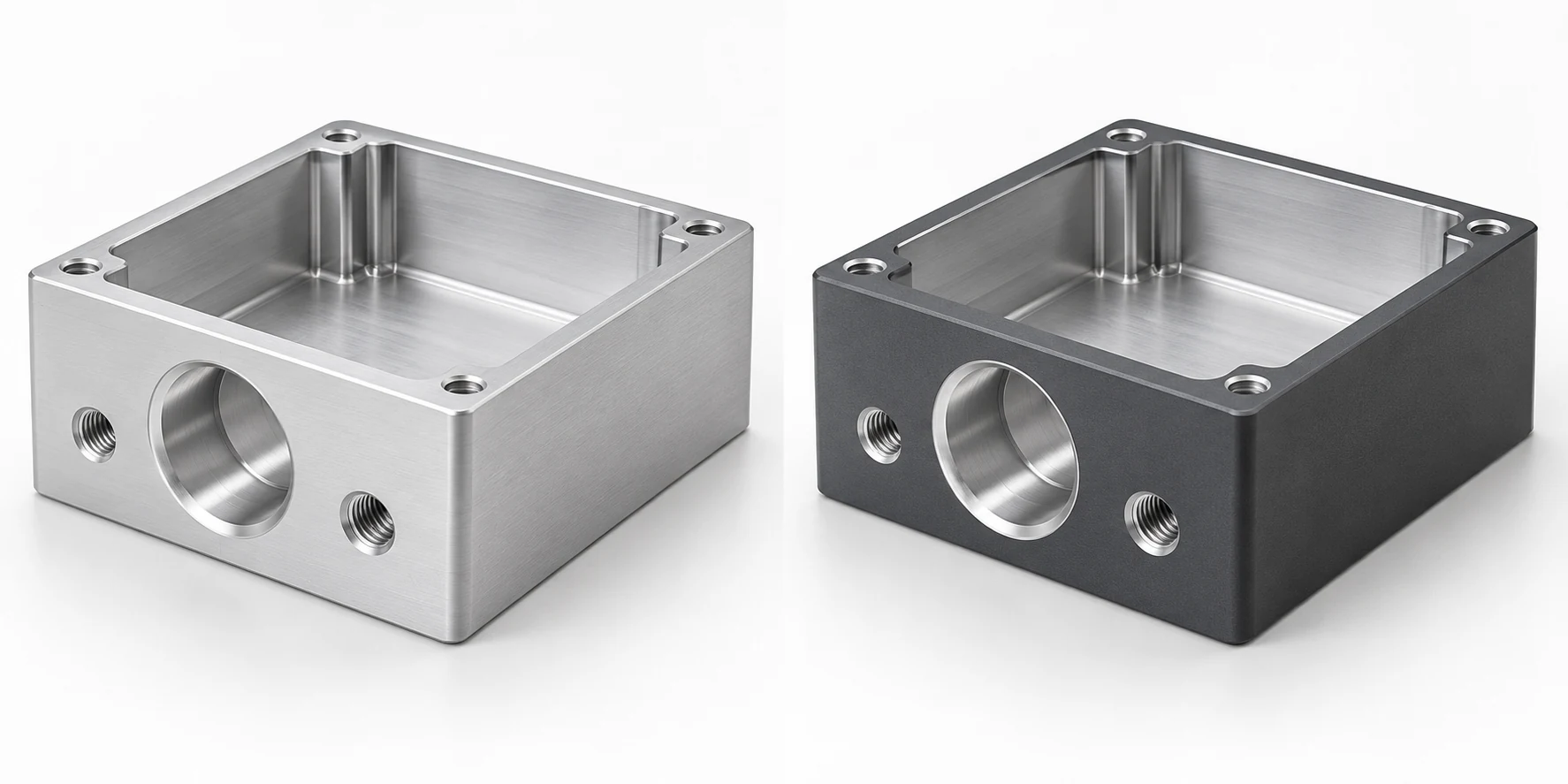
Aluminum: choose anodizing with the final bore and appearance in mind
For a machined aluminum housing, anodizing may serve corrosion, wear or appearance requirements, depending on the coating specification and use. The anodic oxide forms from the aluminum rather than being laid on as paint. That matters for a press-fit bore or a close sliding feature. Part of the oxide grows outward from the original metal surface, while part forms inward. The Aluminum Anodizers Council (AAC) gives a nominal Type II rule of thumb of about two-thirds inward and one-third outward; actual dimensional change depends on the alloy, pretreatment and process. [1]
Take the AAC’s own planning example: a 0.6 mil oxide with nominal one-third outward growth moves each side of an anodized hole inward by 0.2 mil. Across the diameter, the hole is then about 0.4 mil (0.0004 in) smaller before accounting for other process effects. That is material to a bore whose allowed range is narrow. It is not a universal allowance to subtract from every print; chemical etching and actual coating variation can change the result. Specify the finished bore range, then agree whether the bore is coated, masked or finished by an approved later operation. An exterior OD and an internal bore need separate consideration because their mating effect has opposite directions.

Appearance needs a similarly explicit decision. Anodizing does not automatically erase milling marks, scratches or a blasted texture. AAC notes that alloy, temper, gloss, surface structure and coloring route affect the result. For a cosmetic enclosure, name the visible faces, approved color range or sample, surface preparation and any permitted rack-contact area. [4] If a grounding pad must remain conductive, do not let an all-over anodize note silently cover it. If an anodic coating thickness is an acceptance characteristic, ASTM B244 describes an eddy-current measurement method for suitable anodic coatings on aluminum; it does not measure the final bore size for you. [5]
Hardcoat and decorative anodizing should be chosen by function, not by assuming the heavier-sounding name is better. A wear-facing land and a color-controlled front panel may call for different coating properties, thicknesses and appearance expectations. The AAC’s hardcoat guideline treats thickness as a specified, measured property and calls for agreement on relevant openings and threaded holes. [6] The cost and rack implications of an already selected anodizing route are covered separately in our anodizing-cost guide; here the first question is which delivered surface is actually required.
Steel: protect exposed surfaces without sacrificing fit or strength
A carbon-steel or low-alloy-steel bracket exposed to moisture may need a protective finish, but “plate steel” is not enough to define it. ASTM B633-23 covers electrodeposited zinc coatings on iron and steel for corrosion protection, with thickness classes, supplementary finishes and acceptance provisions. [3] The order still needs the applicable coating designation and the part’s exposure and appearance requirements. Neither a smooth bare-machined face nor a generic “silver zinc” description establishes the delivered corrosion performance.
The most common geometry conflict is a thread or fitted seat. A deposited layer occupies space. On an external thread it grows on flanks and crest; inside a tapped hole it reduces available clearance. ISO 2081:2025, for its specified chromium(VI)-treated zinc system, explicitly notes that thread class or fit can limit the coating thickness that can be applied. [7] Identify which threads must assemble in the finished condition and which surfaces may be masked or treated differently. Inspect the specified coating and then verify the actual assembly requirement, rather than assuming that a preplate thread gauge proves postplate fit.

Steel strength can change the route. ASTM B633 says high-strength steel above 1700 MPa should not be zinc electroplated under that specification, and it directs mechanical fastener purchasers toward the applicable fastener specification. That is a specific scope warning, not a claim that every steel part or every zinc method has the same restriction. For a high-strength or fatigue-sensitive part, resolve the material condition and hydrogen-embrittlement controls before choosing a deposit from an appearance photo. [3]
Electroless nickel-phosphorus is another functional metallic coating, sometimes useful when an irregular part needs coverage. ASTM B733-22(2026) describes relatively uniform deposition on irregular geometry where solution can circulate; phosphorus content and any heat treatment affect coating properties. [8] That conditional access matters for a deep blind hole or narrow pocket. Do not substitute it for zinc merely because both are metallic coatings, or assume it will solve an unreachable cavity. First define the target performance, mating dimensions and process access; then select and inspect a coating system that meets them.
Stainless steel: decide whether cleaning, passivation or smoothing is the task
Stainless steel does not become suitable for every service merely because it is called stainless. Grade, surface damage, heat tint, contamination and the actual environment matter. If the part’s surface has free iron from fabrication or handling, chemical passivation may be specified after suitable cleaning. ASTM A967/A967M-25 describes several chemical treatment routes and alternative qualitative tests for their effectiveness; it does not pick one treatment or test for every application. [2] The acceptance question is whether the agreed treatment and test meet the part’s requirement, not whether the part looks shiny.
If oxide scale or heat tint is present, do not expect a passivation note to replace the appropriate cleaning or descaling operation. ASTM A380/A380M-25 treats cleaning, descaling and passivation as related but distinct tasks, and notes that visual inspection can miss thin contamination films. [9] On a fluid fitting, an internal passage also needs adequate solution access, rinsing and drainage. A polished exterior does not demonstrate that the internal surface has received the required treatment.

When controlled smoothing or removal of a damaged surface layer is also required, electropolishing is a different candidate. ASTM B912-26 covers passivation of specified stainless families using electropolishing; under proper process conditions, smoothing and passivation occur together. The result depends on alloy, solution and operation. [10] Electropolishing removes metal rather than depositing a protective film, so a narrow wall, thread or close bore still needs a final-size plan. It is not a universal way to erase deep tool marks, fix a bad fit or reach every concealed area. Our passivation versus electropolishing comparison handles the detailed choice; here the practical gate is whether the job calls for free-iron removal alone or for an additional, measurable surface change.
Appearance starts with the machined surface underneath
A visible face may be brushed for directional grain, blasted for a matte appearance, or prepared before a later coating. These operations can make two identical geometries look very different. They are not interchangeable with protective treatments. The starting tool marks, scratches, material and edge condition still influence the final appearance. The AAC’s anodizing guidance explains that mechanical texture and defects show through anodic oxide rather than being hidden by it. [4] A finish callout that ignores the starting condition can produce a part that satisfies the treatment name but fails the intended look.
Specify appearance on the faces people actually see. A reference sample from the same intended material and preparation can control sheen, color range and allowable marks more effectively than a word such as “satin.” If the finish is directional, identify its lay relative to a named edge on the drawing. If a functional face has a numerical texture requirement, give its parameter, location and measurement condition separately. Our brushed-finish guide covers grain direction and samples in detail; this selection guide uses those controls only after brushing is the chosen route.

Abrasive treatment also has geometric consequences. A broad face can receive uniform contact more readily than the floor of a narrow recess beside a tall wall. An edge can lose its intended break if abrasive work is aggressive; an opening can show a different texture transition from the surrounding panel. For blasting, abrasive type and shape affect the resulting profile and appearance; ISO 11124-1:2026 discusses this in the context of metallic abrasives used primarily for steel preparation. [11] That source does not make blasting a corrosion coating or establish one universal roughness for aluminum housings. If the part needs both a cosmetic texture and corrosion protection, the downstream treatment still needs its own compatible specification and acceptance.
Check recesses, masking and contact locations before approving a route
A finish reaches a real shape, not the shaded area of a CAD view. A blind pocket may trap solution or block circulation; a narrow gap may be difficult to rinse; a high wall can interrupt brushing. A coating process can require electrical contact or a support point that leaves a local mark. For anodizing, the AAC specifically notes the need for rack contact and that masking a flat area can be more difficult than plugging a hole. [1] A part whose only permissible contact face is its primary cosmetic surface has a design conflict before the first batch is run.
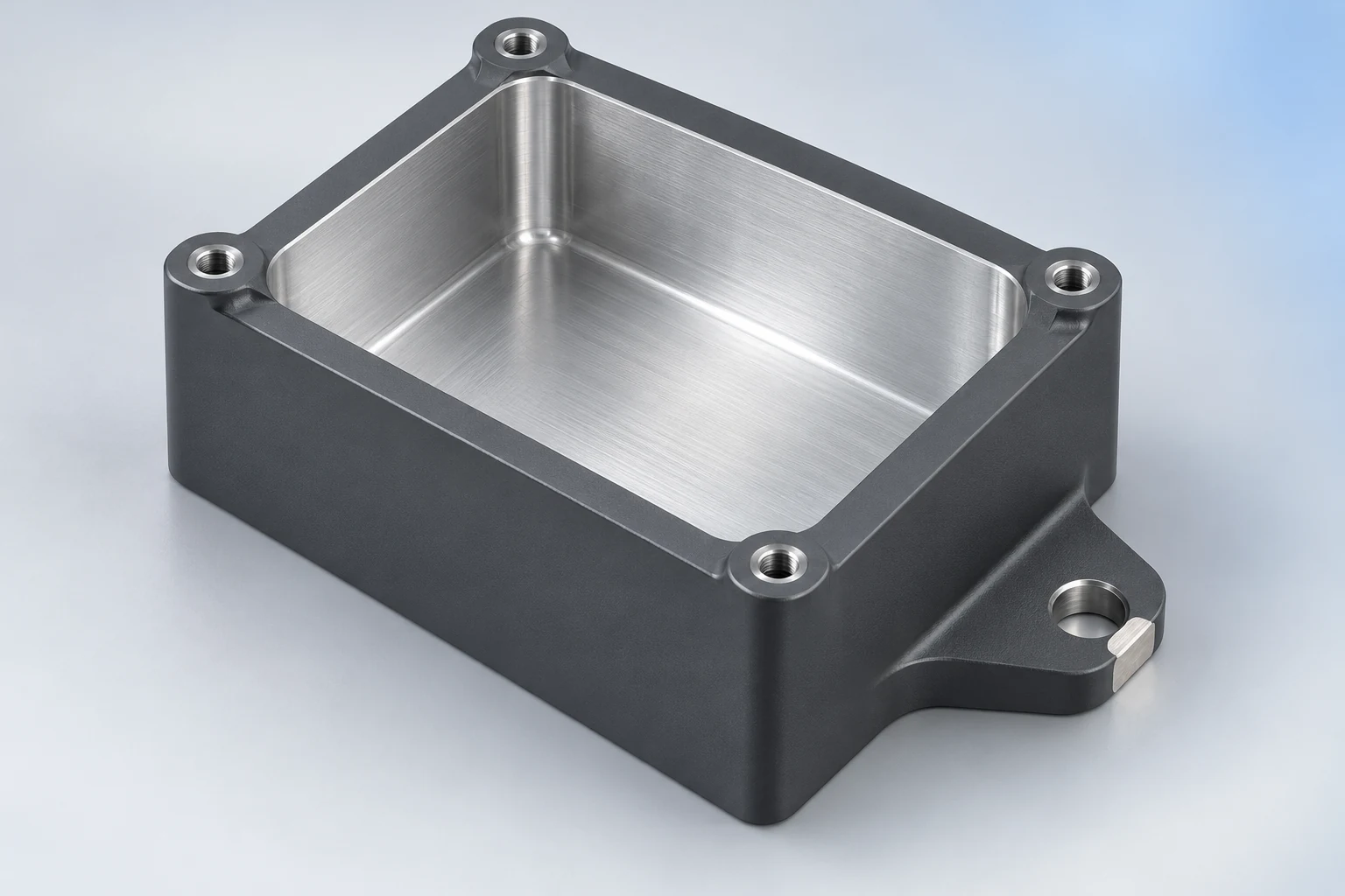
Use a marked drawing to separate three kinds of area: must receive the treatment, must remain in another specified condition, and may carry a contact or transition mark. A fitted bore might be masked; an electrical pad might need a bare region; a hidden edge might accept a rack mark. These are not free options. Plugs, masks, contact location and post-treatment cleaning add handling and can change which orientation or lot arrangement is feasible. For an electroless deposit, ASTM B733’s relatively uniform thickness statement is conditional on solution circulation. [8] State a difficult internal-surface requirement explicitly rather than assuming the exterior result proves it.
When masking would create a fragile edge or uncontrolled transition at a critical interface, re-examine the design. A different finishing sequence, a local final-machining operation, a revised boundary or a different coating may be more reliable. A requirement that cannot be reached or measured on the actual geometry should be resolved before a process is locked into a drawing. The answer depends on the part, not on a general promise that a shop can mask “as needed.”
Write the finish as a final-part requirement
A useful finish note connects the substrate, process, treatment zone and acceptance to the delivered part. It is possible to specify too little (“black finish”) and to specify too much by copying a full standard without identifying the actual functional surface. The following order avoids both failures. If a trial shows that a candidate process cannot meet the result, return to the route decision rather than accepting a defective part because the process name was followed.
- Identify the base material and its condition. Use the alloy or grade and state that affects the treatment, including a heat-treated condition where relevant. A color sample from another alloy is not automatically representative.
- Assign the surface jobs. Mark fit, sealing, contact, wear, corrosion-exposed and visible areas. Name the actual environment and required appearance or functional result.
- Choose the process and applicable specification. State the treatment family, required class/type or coating system, and any necessary pretreatment or sealing. Use the edition required by the order rather than silently changing it.
- Draw the boundaries. Mark treated and excluded zones, permissible rack/contact positions, masked threads or bores, and any required texture direction or reference sample.
- Define the delivered geometry. Put critical size, form and thread-fit limits on the part after all specified finishing. Agree any prefinish machining allowance separately with the producer.
- Set acceptance at the relevant locations. Choose treatment-appropriate coating thickness, cleanliness/passivation, appearance, adhesion or corrosion tests only where they matter, plus final-part dimensional inspection. A single visual approval does not measure all of these.
For the aluminum housing concept, a drawing with a defined F-1 finish schedule, controlled sample S-1 and identified features could carry a compact note like this:
Apply anodic oxide to marked exterior faces per finish schedule F-1 (ASTM B580-25 coating type and thickness). Leave locating bore B and grounding pad G uncoated. Rack contact is permitted only on rear tab R. Finished bore B shall meet its drawing size limits. Compare marked exterior faces with approved sample S-1; measure coating thickness at exterior location E and verify finished bore B size.
The finish schedule must contain the actual coating type, thickness and any required sealing or color condition. Bore B’s limits remain with the dimensional drawing rather than being replaced by a generic anodizing allowance. ASTM B580-25 covers anodic oxide requirements on aluminum and allows application-specific properties to be agreed by the buyer and manufacturer. [15]

Inspection method matters as much as the number written beside it. ASTM B244 addresses eddy-current measurement of suitable anodic coatings, while ASTM D7091-22 addresses dry-film thickness measurement of nonmagnetic coatings over metal and notes that thickness varies across a surface. [5] [12] A coating reading at one easy exterior spot may miss a critical recess; a prefinish gauge result may miss a postfinish fit failure. Select sample locations and the relevant final condition. Where a visual finish is specified, retain an approved sample and agree which faces it governs. The acceptance package should test the specified outcome rather than collect every possible report.
Three part concepts lead to different finish decisions
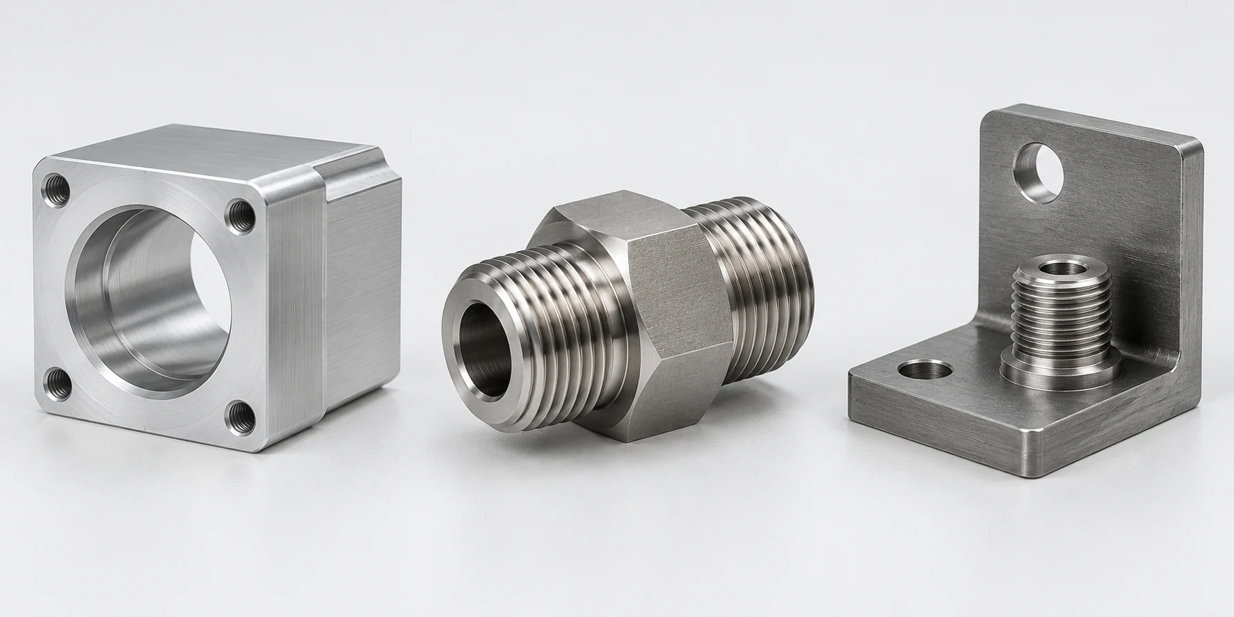
Aluminum control housing with a fitted bore
Assume an aluminum housing has a colored visible exterior, a close-fitting alignment bore, a threaded mounting hole and a grounding pad. The exterior might be a good anodizing candidate, but the bore fit and grounding function prevent an unqualified “anodize all surfaces” note. Choose the coating specification for the exterior and its actual exposure. Decide with the finisher whether the bore will be coated with a machining allowance, masked or brought to size by an agreed later process. Identify the pad’s required electrical condition and an acceptable rack-contact position. Inspect exterior appearance and coating at designated areas, then check the finished bore and assembly fit. If the design later relaxes the bore fit, that change may simplify masking; it does not change the need to define the final delivered condition.
Stainless fluid fitting with an internal passage
Assume a machined stainless fitting has residual shop contamination and an internal wetted passage. If the principal concern is free iron, the route starts with suitable cleaning and a specified passivation treatment and effectiveness check. If the passage must also meet a separate surface-roughness or cleanliness target that cleaning/passivation will not provide, evaluate electropolishing or another controlled preparation while checking access, rinsing and allowable metal removal. A glossy outside and an unverified bore are not a passing result. If the actual passage geometry cannot be reached or inspected to the requirement, revise the route or the geometry instead of relying on the finish label.
Threaded steel bracket for a wet environment
Assume a steel bracket has a threaded attachment and exterior surfaces exposed to moisture. A specified zinc system is one candidate for corrosion protection. Thread class and final mating fit constrain the useful deposit; the coating’s supplementary treatment and inspection must match the exposure and order. If the steel is in a high-strength condition, review the applicable process and hydrogen-embrittlement requirements before placing it on a zinc-plating line. If the bracket is redesigned with a non-threaded insert interface or a different material, the finish decision may change. The correct quote and inspection compare accepted brackets in their delivered state, not bare parts followed by an unspecified “protective coating.”
Technical sources
- Aluminum Anodizers Council, Anodized Aluminum FAQ. Anodic growth and dimensional examples, masking and rack-contact questions.
- ASTM International, A967/A967M-25: Chemical Passivation Treatments for Stainless Steel Parts. Public scope and alternative effectiveness tests.
- ASTM International, B633-23: Electrodeposited Zinc Coatings on Iron and Steel. Public scope, coating classes and high-strength steel/fastener limits.
- Aluminum Anodizers Council, Anodic Coating Specifications. Alloy, temper, surface preparation and agreed appearance range.
- ASTM International, B244-09(2021): Eddy-Current Thickness Measurement of Anodic Coatings on Aluminum. Public measurement scope and thin-conversion-coating limit.
- Aluminum Anodizers Council, Application Guideline for Selection of Hard Anodic Oxide Finishes. Coating-thickness measurement and application-specific agreement.
- ISO, 2081:2025, Metallic and Other Inorganic Coatings — Electroplated Coatings on Iron and Steel Using Zinc Treated with Solutions Containing Chromium (VI). Public threaded-fit limitation for this specified coating system.
- ASTM International, B733-22(2026): Autocatalytic Nickel-Phosphorus Coatings. Public scope, circulation and property conditions.
- ASTM International, A380/A380M-25: Cleaning, Descaling, Pickling, and Passivation of Stainless Steel. Public scope and contamination/inspection distinctions.
- ASTM International, B912-26: Passivation of Stainless Steels Using Electropolishing. Public scope and simultaneous smoothing/passivation conditions.
- ISO, 11124-1:2026, Metallic Blast-Cleaning Abrasives. Abrasive type and shape in steel-preparation context.
- ASTM International, D7091-22: Dry-Film Thickness Measurement of Nonmagnetic Coatings on Metal. Measurement location and variation context.
- Powder Coating Institute, What Is Powder Coating? Electrostatic application to metal and the curing step.
- Powder Coating Institute, Powder Coating Glossary of Terms & Definitions Pretreatment, film build and recess-related application limits.
- ASTM International, B580-25: Anodic Oxide Coatings on Aluminum. Public scope and buyer/manufacturer agreement on application-specific coating properties.