On this page
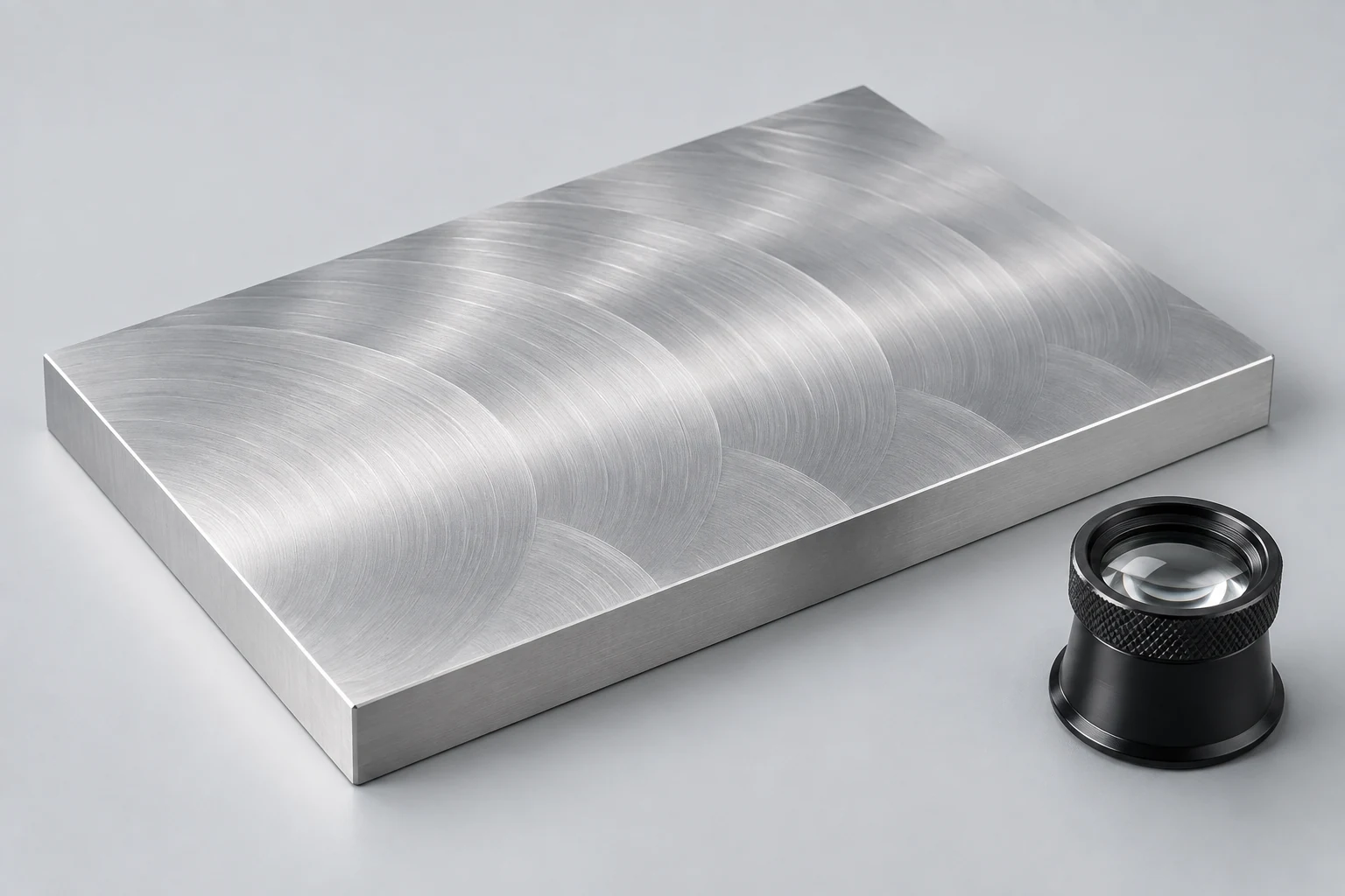
Visible milling marks can be acceptable when the part meets its dimensional, geometric, surface-texture and agreed appearance requirements. A regular cutter pattern is not automatically a defect. A local score, raised material or a change in texture on a working surface needs a closer check; a photograph alone cannot establish the cause or decide acceptance.
The useful decision is whether the affected surface already meets its requirements, needs further inspection, or would benefit from a different finish. Removing marks simply because they are visible can change a feature that was otherwise correct.
Read the marks before changing the surface
Milling leaves a surface as successive cutting edges and passes remove material. Their overlap can produce arcs, parallel lines or transitions between paths. Cutter geometry and cutting conditions influence that pattern. Sandvik Coromant’s discussion of machined surface finish distinguishes visible marks from required surface quality; our guide to how CNC milling works places them within the machining sequence. [1]
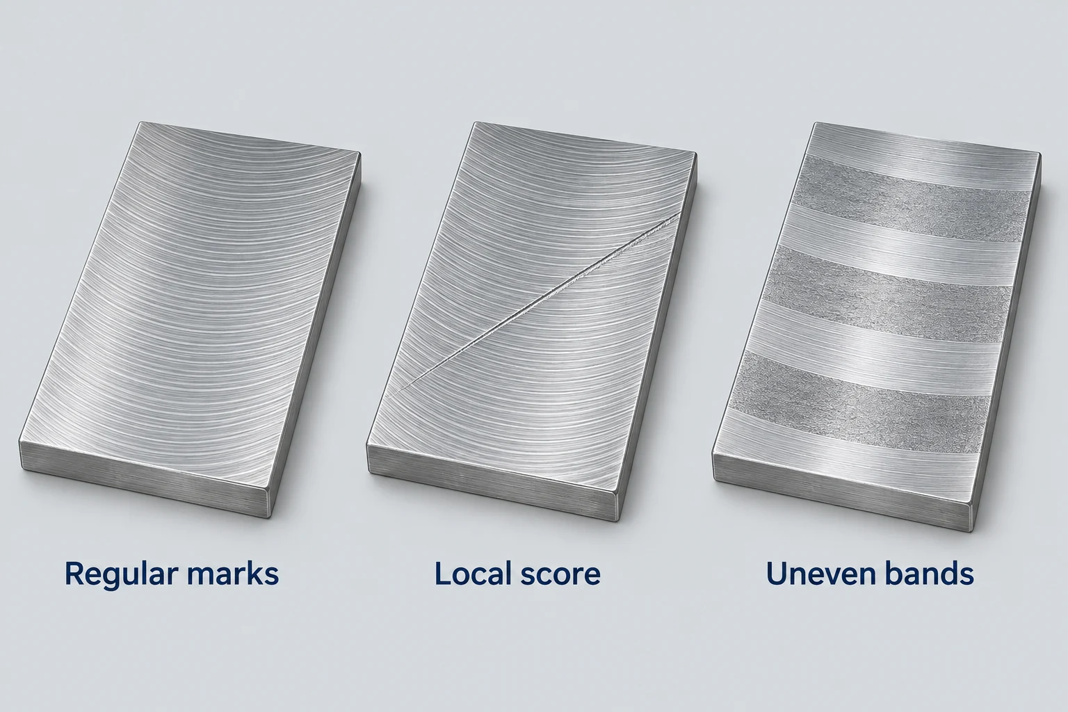
Look for a difference between a repeated pattern and a localized interruption: an isolated groove crossing the pattern, a torn-looking patch, a raised edge or uneven bands. These are observations to record, not diagnoses. Vibration, cutting-edge condition and other process conditions can affect the surface; similar appearances can have different causes. [1]
Compare like areas under consistent lighting. A reflection can make an otherwise subtle pattern prominent, while another angle can hide it. Record that change in visibility without treating either view as a roughness measurement.
Before polishing or blasting anything, record the affected location on the drawing and photograph the overall face as well as the local mark. Retain the part’s identity and current condition for the review. Ask which check would distinguish an appearance issue from a texture, size or form problem. A close-up without the feature’s location is much less useful.
Judge the affected surface by its job
Start with the released drawing and agreed order requirements, including general notes, referenced specifications and any approved appearance sample. A surface without its own local finish callout may still be covered elsewhere. When the requirement is missing or unclear, resolve it with the responsible engineer instead of inventing a roughness limit at receiving.
Ra averages the absolute height deviations of a roughness profile from its mean line over the evaluated length. It is not a visual grade, a scratch-depth limit or a flatness result. Measurement direction and evaluation conditions matter, and an average does not describe every local feature. NIST’s metrology guidance explains profile evaluation, while Mitutoyo’s surface-roughness bulletin distinguishes roughness, waviness and surface flaws. [2]
| Affected surface | Deciding requirement | Useful check | Disposition |
|---|---|---|---|
| Noncritical internal face | Specified surface and edge condition | Applicable notes; local raised material | Retain the texture if requirements are met |
| Visible cover face | Agreed appearance | Reference sample and viewing conditions | Discuss a cosmetic change if appearance falls short |
| Mounting or seating face | Specified geometry and texture | Flatness, orientation and texture as required | Measure the relevant characteristic before rework |
| Sealing or sliding face | Interface-specific surface condition | Mark location, direction and applicable texture limits | Review the interface before changing its finish |
| Close-fitting bore | Final size, form and texture | Specified bore checks at the affected area | Evaluate removal or treatment against the fit |
A roughness report also needs to refer to the relevant location and measurement conditions. A trace taken elsewhere on a broad face cannot, by itself, settle a concern about one isolated mark. Request the check that addresses the disputed area instead of using an unrelated average as the answer.
The same visible line can therefore call for different actions on an enclosure wall and a sealing face. If a part meets the specified Ra but has a local groove, check any separate surface-defect requirement and the interface’s needs. If geometry is out of tolerance, an attractive cosmetic finish does not resolve that failure.
Choose a finish for the problem it can solve
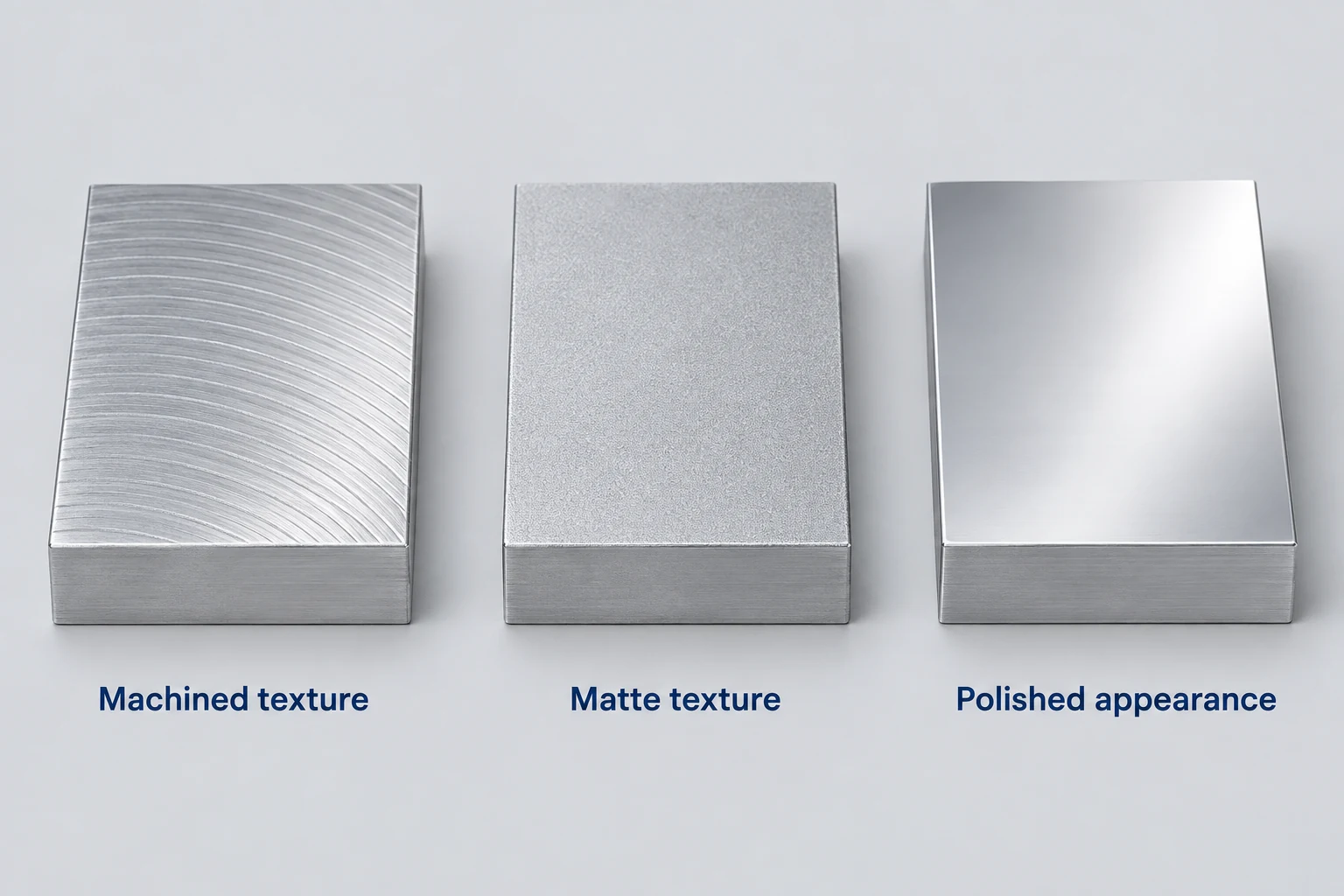
Keep the as-machined surface when it satisfies the required function and appearance. There is no need to erase all evidence of cutting merely to make the part look more finished. This decision still includes the specified edge treatment and any applicable surface restrictions.
Consider a matte treatment for an appearance requirement. Abrasive blasting can create a different texture on suitable parts, but a matte surface is not evidence that an underlying score has been removed. Review the actual starting surface and a representative treated sample when appearance drives the choice. Do not approve the process name alone as the acceptance criterion. [3]
Consider controlled abrasive finishing when material must be removed. Polishing or blending may reduce machining marks, but removing material also changes the surface being accepted. The required removal, remaining dimensions and edge shape govern whether the operation is suitable. 3M’s abrasive-product guidance lists both machine-mark removal and edge-breaking or radiusing applications, illustrating why the boundary matters. [4]
Choose anodizing for its specified surface properties and appearance on suitable aluminum. It is not a substitute for correcting an unacceptable machined surface. A scratch or gouge extending into the base metal needs its own corrective operation; renewing the oxide layer does not remove it. The coating also affects dimensions. Agree the preparation and final condition as part of the treatment. [5]
Our CNC milling service distinguishes as-machined, bead-blasted and anodized delivery conditions. A proposed finish should state the problem it addresses and the surfaces it changes.
Protect functional features before rework
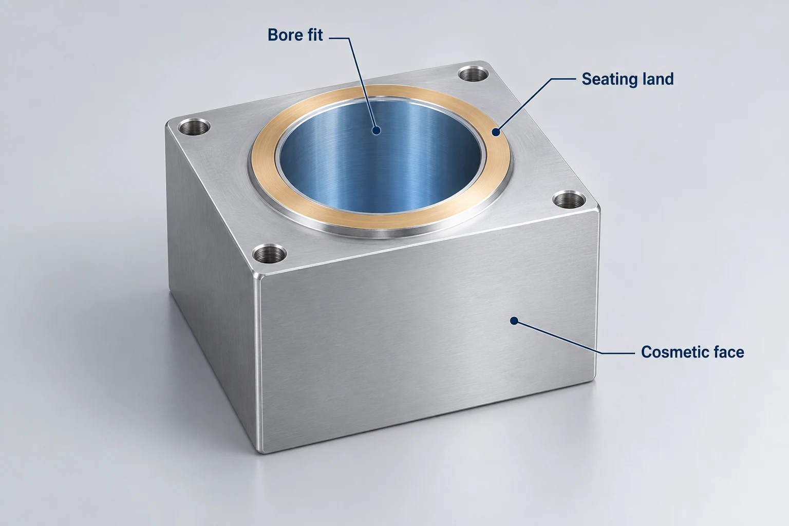
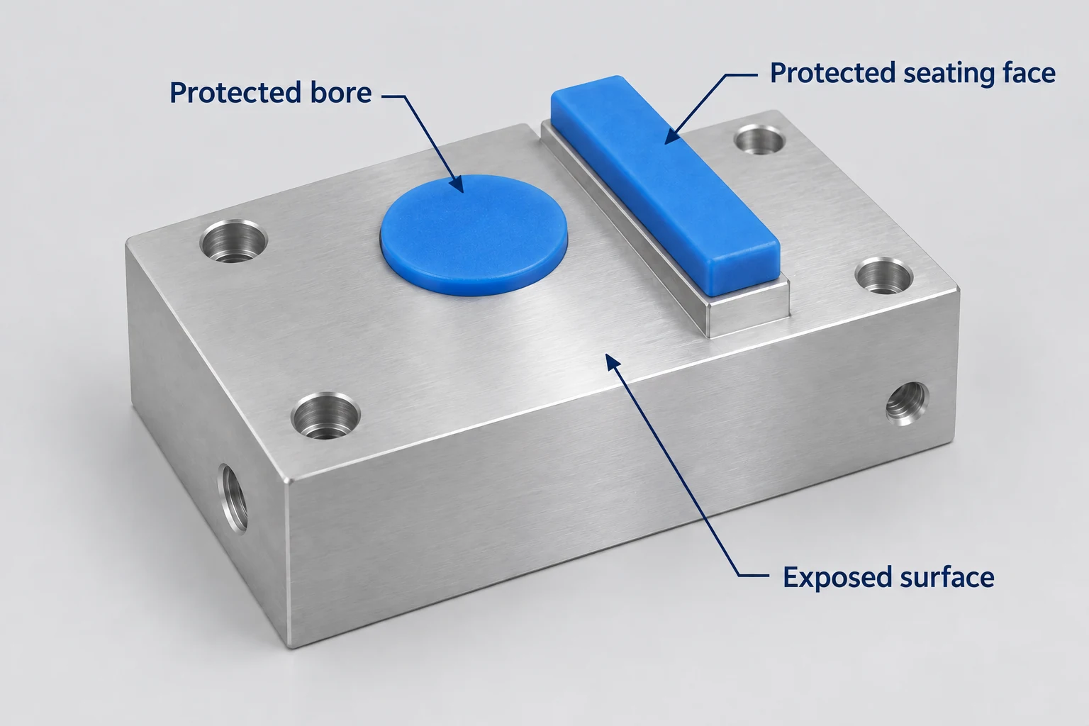
Consider a housing whose exterior needs a more uniform appearance while its bore locates another component. Treating both areas identically could change the bore even though the complaint concerns the outside. Define where the proposed work starts and stops, and which seating lands, threads, edges or contact areas must retain their required condition.
For material-removing work, assess the remaining dimensional allowance and edge shape before agreeing to blend a mark away. For anodizing, address coating thickness and dimensional change, including whether selected areas need masking. Masking is a process-specific proposal to review with the processor, not a promise that every protected boundary will be invisible. [4] [5]
Record the approved change and verify the characteristics it can affect in the required final condition. If the surface cannot be brought into compliance without losing a functional dimension or edge, cosmetic rework is not an adequate disposition. The engineering review must address the part’s remaining requirements.
For the next order, carry those surface zones, appearance references and final inspection conditions into the drawing package. The CNC machining RFQ guide shows how to connect that definition to the rest of the purchasing scope.
Milling marks FAQ
Can two parts with the same Ra look different?
Yes. Ra summarizes profile heights; it does not fully describe the pattern, direction or spacing of the texture. Parts can share an Ra value while having different appearances. Use a separate appearance reference when visual consistency matters. [2]
Does “as-machined” mean any milling mark is acceptable?
No. It identifies a delivered surface condition, not permission to ignore drawing requirements. Size, geometry, surface-texture limits, edge condition and any agreed appearance criteria still apply.
Can a fingernail test decide whether a scratch passes?
No. Feeling a mark may help locate it, but it does not measure its depth or establish compliance with a specified texture or defect limit. Use the inspection method appropriate to the affected requirement.
Should the entire part receive one cosmetic finish?
Only when that treatment is compatible with all affected surfaces. A visible exterior, a fitting bore and an electrical contact can need different treatment boundaries. Specify the zones instead of extending a cosmetic change across the whole part.
Technical sources
- Sandvik Coromant. Milling—Principles, “Surface finish of a machined part,” publisher preview; and Solving Everyday End Milling Challenges, published by Fastenal, March 9, 2026. Visible machining marks and factors affecting milling results.
- NIST. Introduction to Surface Finish Metrology (2010). Profile evaluation and roughness parameters. Mitutoyo. Surface Roughness Measurement, Bulletin No. 1984. Surface components and measurement considerations.
- Herb Tobben, Clemco Industries. Surface Finishing: It’s All About Lookin’ Good, The Shot Peener, Fall 2004. Blasting media, processing conditions and a matte-finish application.
- 3M. Standard Abrasives — Coated, Bonded & Non-Woven Product Line. Machine-mark removal, polishing, edge breaking and radiusing applications.
- Aluminum Anodizers Council. Anodized Aluminum FAQs. Dimensional effects, masking and damage that extends into the base metal.



