On this page
CNC (computer numerical control) milling is a subtractive manufacturing process in which a rotating cutting tool removes material from a workpiece under computer control. The machine coordinates the movement between the cutter and the material to produce features such as flat faces, pockets, slots, holes and curved surfaces. Rather than adding material layer by layer, it cuts away what the finished part does not need. [1]
The usual workflow is to define the part, plan the tools and toolpaths, prepare the machine and workholding, remove material, and inspect the result. Two similar-looking parts can still require different tools, setups or machining sequences.
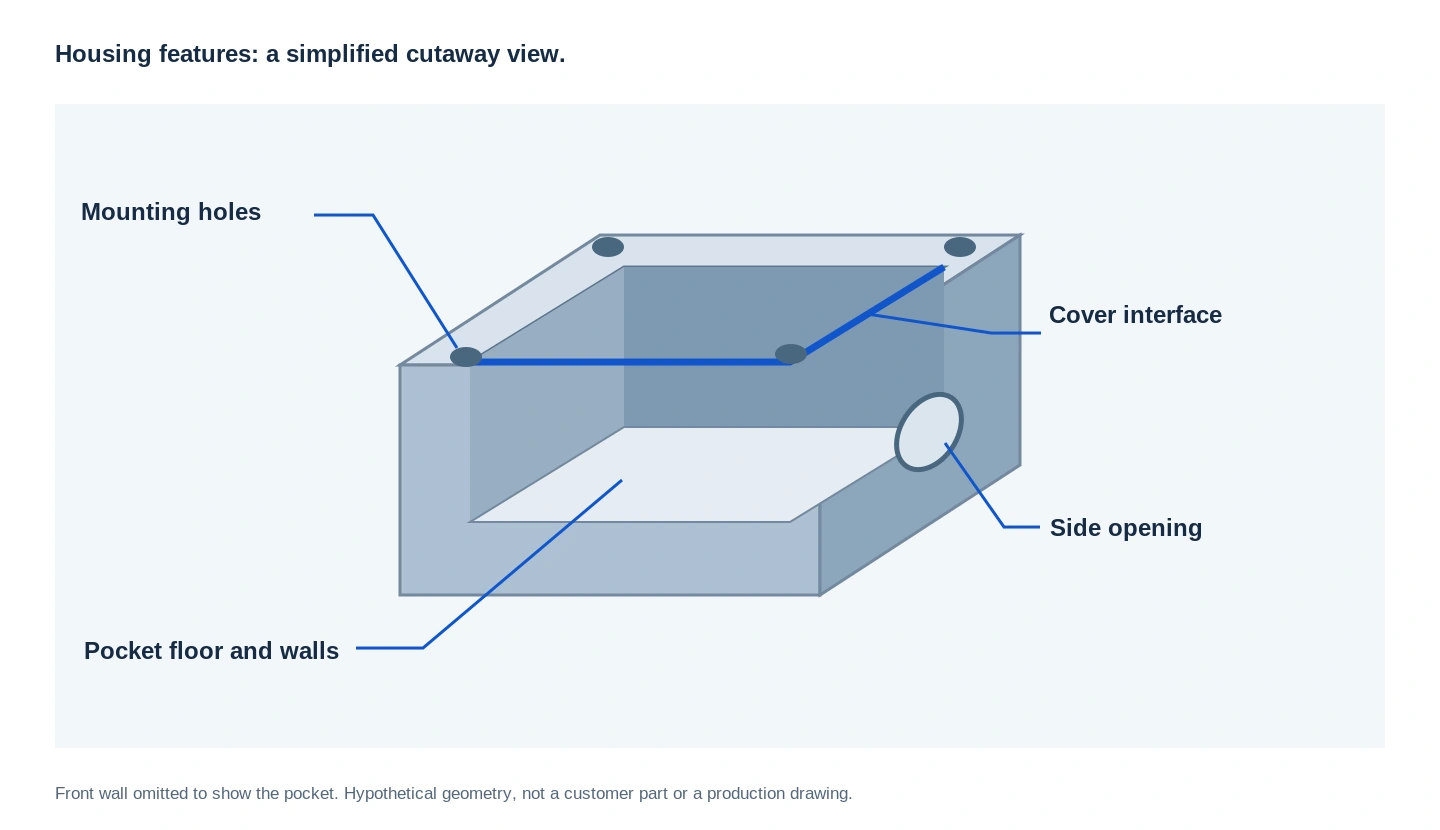
Consider a housing with an internal pocket, a cover seat and several mounting holes. Its shape is only part of the problem. The machinist also needs to decide how to hold it, how the cutter will reach each feature, which surfaces establish its position and when to machine the areas that control assembly. The same questions appear across many CNC-milled part shapes, even when their applications differ.
Understanding CNC milling means connecting those decisions to the finished part—not simply counting how many axes a machine has. For the equipment itself, our guide to milling machine parts, motion and uses explains the spindle, table and controls.
Header image: Illustrative CNC milling scene. AI-generated image, not a photograph of vetcnc facilities.
What actually moves during CNC milling?
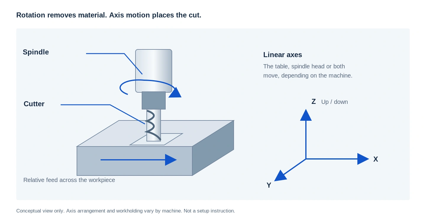
The spindle rotates the cutter, while the machine’s axes control its position relative to the workpiece. Depending on the machine configuration, the table, spindle head or both may move. A CNC program coordinates this motion with tool selection, spindle speed and feed rate. The useful distinction is between the cutter’s rotation and the programmed movement that carries it through the material. [2]
As a milling cutter rotates, its cutting edges enter and leave the workpiece repeatedly. Each engagement removes material as a chip. The angle and extent of contact change as the cutter enters a pocket, moves beside a wall or travels around a corner. This is why a tool can behave differently along one continuous path, even when the programmed spindle speed remains unchanged. [3]
In conventional turning, the workpiece rotates while a cutting tool feeds against it. Milling is different because the rotating cutter supplies the primary cutting motion. This makes milling useful for features that are not centered on a single rotational axis. A component can require both processes: a shaft might be turned for its diameters and then milled to add a flat or keyway. [4]
For someone reading a part drawing, a helpful first question is: which features are organized around an axis, and which require a cutter to travel across a face or around a profile? Our machining process comparison places these operations alongside drilling, boring and other processes.
How a CAD model becomes a milling program
The model defines the shape; CAM defines how to cut it
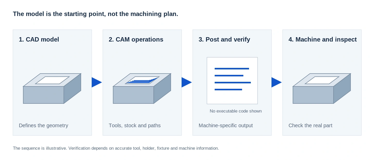
A CAD (computer-aided design) model describes geometry. CAM—computer-aided manufacturing—uses that geometry to develop machining operations. The programmer selects tools, defines the stock and setup, chooses cutting strategies and calculates toolpaths. A single model can support several possible machining routes; creating the model does not, by itself, decide how the part will be manufactured. [5]
Imagine that our housing includes a large pocket and a small groove around its opening. Using one small cutter for everything might avoid a tool change, but that does not automatically make it a better plan. A larger cutter could remove the open pocket material, while a smaller cutter handles the groove and remaining details. The manufacturing decision concerns the sequence, not just whether a tool can fit.
The program must match the actual machine
A post-processor converts CAM operations into instructions appropriate for a particular machine and control. These instructions commonly include G-code, along with commands for tool changes, spindle operation and other machine functions. The same CAM setup should not be assumed to produce a ready-to-run program for every machine configuration. [5]
Simulation can help identify collisions, travel-limit problems and unintended material removal before machining. Its usefulness depends on the machine, tool, holder, fixture and stock information represented in the simulation. A successful simulation is a valuable check, but it does not prove that the physical setup has been assembled correctly. [6]
Workholding and offsets connect the program to the real part
The workpiece needs secure, repeatable support. A vise may suit rectangular stock, while another component may need shaped jaws or a dedicated fixture. The machine also needs the workpiece location and the relevant tool dimensions, established through work and tool offsets. These connect the programmed coordinates to the actual cutting position. [7]
For the housing example, this raises a practical question: after the internal pocket has been cut, what remains available for clamping when the part is turned over?
That question belongs in the process plan before material is removed. Otherwise, an apparently straightforward first operation can leave an awkward second setup.
Which milling operations create which part features?
“Milling” includes several kinds of cuts. The operation is selected around the surface or feature that needs to be produced, rather than around the overall name of the component. [1]
| Part feature | Common operation | What the cutting tool does |
|---|---|---|
| Broad, flat face | Face milling | Sweeps across a surface to remove material and establish a face |
| Vertical wall or step | Shoulder or side milling | Uses the side of the cutter to generate a wall, often together with an adjacent face |
| Internal recess | Pocket milling | Clears material within a boundary while retaining surrounding walls |
| Slot or channel | Slot milling | Removes material along a narrow path using suitable tooling |
| Curved surface | Profile or surface milling | Follows the shape through a series of coordinated passes |
| Beveled edge | Chamfer milling | Creates an angled edge with a cutter suited to the required geometry |
These operations describe different cutting tasks, and one component can contain several of them. Face, shoulder, pocket and chamfer milling should not be treated as competing manufacturing methods for the entire part. [8] [9] [19]
Cutter shape determines which surfaces it can generate
An end mill can use its side edges to produce walls and, when designed for the operation, its end geometry to cut floors or enter material. A ball-nose cutter has a rounded end that is useful for following curved surfaces. Face mills and chamfer cutters provide different cutting geometries for their respective tasks. The cutter’s diameter, usable length and edge shape all affect access to the feature. [9]
This creates an important distinction between the tool fitting inside the feature and the tool being suitable for machining it. A cutter may have enough diameter clearance but require excessive reach, or its holder may interfere with an adjacent wall.
Holes on a milling machine are not always made by milling
A machining center can use drills, boring tools, reamers and taps as well as milling cutters. A hole might be drilled, enlarged by boring, finished by reaming or produced through circular milling. Threads may be tapped or thread-milled, depending on the feature and process.
Calling the machine a “mill” does not mean every operation performed on it is technically milling. The required diameter, depth, position, finish and tool access help determine the appropriate method. [10]
Why a milling cutter does not simply trace the CAD outline
The tool center follows a different path from the cutting edge
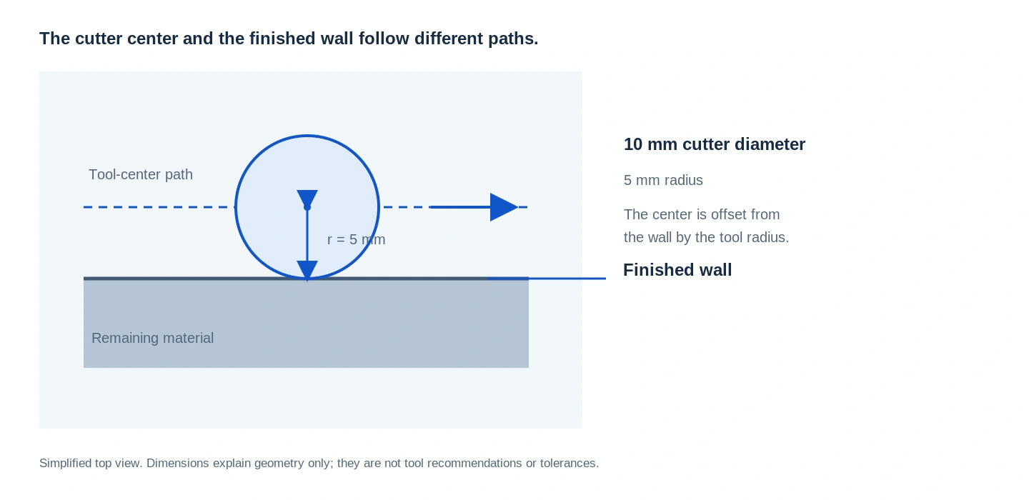
A cutter has a physical diameter. To machine a wall, its center normally travels at an offset from the desired surface, accounting for the cutter radius. CAM calculations and cutter compensation help manage the relationship between the programmed path and the surface generated by the cutting edge. [11]
For a simple geometric illustration, imagine a circular cutter with a 10 mm diameter beside a straight wall. Its center is nominally 5 mm from the wall when its outer edge touches that surface. This is a geometric relationship—not a finished-part tolerance or an instruction for setting up a machine.
Once the tool reaches an internal corner, the problem changes. More of its circumference may engage with material, increasing the cutting load. Tool diameter and corner geometry therefore influence more than the smallest radius the tool can physically reach. [12]
Roughing and finishing serve different purposes
Roughing removes the bulk of the unwanted material. Finishing establishes the remaining surfaces and dimensions using a process suited to those requirements. Between them, semi-finishing or rest machining may prepare particular areas or remove stock that a larger cutter could not reach.
These are stages of machining, not necessarily different types of machines. The toolpath used to remove a large volume of stock does not have to be the same path used to produce the final wall or surface. [9]
In our housing example, the pocket could be cleared while leaving material on its walls and floor. Later passes would then address the final pocket dimensions and the cover seat. This separates the task of removing stock from the task of completing the functional surfaces.
Entry moves and cutter engagement matter
A toolpath includes how the cutter enters material, how it stays engaged and how it leaves. Ramping, helical entry and other approaches can provide alternatives to a straight plunge when the cutter and available space permit them. Along the cut, changes in engagement affect the loads experienced by the cutting edges. [10]
A path that looks short on screen is not automatically the most productive or stable path. Avoiding abrupt engagement changes can be more useful than simply minimizing travel distance. [3]
How spindle speed, feed and depth of cut work together
Spindle speed describes cutter revolutions per minute; feed rate describes travel per minute. Cutting speed is the speed at the relevant cutting diameter. Feed per tooth relates the advance to the spindle speed and effective tooth count. Axial depth and radial engagement describe how much of the cutter participates in the cut. [13]
A simplified feed calculation illustrates the relationship:
Feed rate = spindle speed × effective tooth count × feed per tooth
For example, an assumed speed of 6,000 rpm, four effective teeth and 0.04 mm feed per tooth gives:
6,000 × 4 × 0.04 = 960 mm/min
These numbers are only an arithmetic example. They are not recommended cutting data for any particular material or tool.
Changing rpm without adjusting feed changes the advance per tooth. Changing the cutter diameter changes cutting speed at the same rpm. Actual chip thickness also depends on engagement and cutter geometry. [13]
The practical lesson is that “run it faster” is not a complete machining strategy. The material, tool, reach, fixture and cut must be considered together.
Climb milling and conventional milling describe the direction of engagement
In peripheral climb milling, the chip generally starts thicker and becomes thinner as the cutting edge leaves the material. Conventional milling reverses that progression. The choice affects cutting forces, rubbing and how the workpiece interacts with the cutter.
Climb milling is commonly preferred when the machine, fixture and workpiece allow it, but it is not an unconditional rule. Backlash and workholding behavior are among the factors that need consideration. [14]
What changes between three-axis and five-axis milling?
Additional axes mainly change how the cutter and workpiece can be oriented relative to one another. They do not remove the need for suitable tooling, support and a sound process. [15]
| Configuration | How it works | What it changes |
|---|---|---|
| Three-axis milling | Coordinates movement along X, Y and Z with a fixed tool orientation relative to the setup | Machines features accessible from that direction; other faces may need another setup |
| Four-axis milling | Adds a rotary axis | Can reposition or rotate the workpiece to reach features around it |
| 3+2 machining | Uses two rotary axes to establish an orientation, then cuts with those rotary positions held | Provides access from several fixed orientations without necessarily using simultaneous five-axis motion |
| Simultaneous five-axis machining | Coordinates linear and rotary movement during cutting | Allows tool orientation to change along a surface or feature |
The distinction between 3+2 positioning and simultaneous five-axis cutting is about whether orientation changes during the cut, not simply whether two rotary axes are present. [4] [15]
Three-axis machining can produce accessible curved surfaces through coordinated X, Y and Z movement. A three-dimensional CAD model therefore does not automatically require simultaneous five-axis machining. [15]
For our housing, a pocket and holes accessible from above might be handled in one orientation. A side port requires another approach. Depending on the geometry and available equipment, that could mean reclamping the part, indexing it with a rotary setup or using a multi-axis machine.
The right question is not “Which machine has the most axes?” It is “Which setup reaches the required features while maintaining their relationships?” The 5-axis machining overview provides a separate place to review that project route.
A pocketed housing shows how the steps fit together
Consider a hypothetical aluminum housing with an open rectangular pocket, an internal ledge for a cover, four mounting holes and a connector opening on one side. The following sequence illustrates the planning questions. It is not a production plan for a real customer part.
Establish the references and preserve a way to hold the part
First, identify the features that matter to assembly. In this example, assume that the cover sits on the internal ledge and that the mounting holes locate the housing on another component.
Those relationships would guide the choice of references and the inspection plan. The setup also needs enough supported material for the first operations and a workable holding arrangement for later access.
For discussion, we could retain suitable external stock during early machining rather than immediately finishing every outside face. The point is to decide how the second setup will work before completing the first one.
Remove open material before addressing the smaller details
A possible approach is to establish the required reference face, rough the main pocket and then use appropriate finishing passes for its walls and cover seat.
A smaller cutter could address details left by the larger roughing tool. The mounting holes would use the hole-making sequence selected for their requirements. A chamfering operation could then handle specified accessible edges.
This example deliberately separates the cutting jobs. It does not assume that one cutter, one feed setting or one continuous operation should produce every feature.
Reorient the housing and verify the relationships
The side connector opening introduces a new access direction. A second setup or suitable rotary positioning would need to relate that operation to the already-machined features.
The final review would not stop at whether the pocket “looks right.” It would ask whether the cover seats as intended, whether the mounting holes have the required relationship to their references and whether the side opening is correctly positioned.
If a later coating or surface treatment affects a functional interface, that interface needs an agreed final acceptance condition. In this hypothetical case, that would mean deciding whether the cover fit is assessed before treatment, after treatment or through a defined sample approval.
The example shows why milling is a sequence of connected decisions. Removing the correct volume of material is necessary, but it is not the same as proving that the finished component performs its intended function.
Why the material changes the milling strategy
The same geometry does not imply the same cutting conditions in every material. Steel machinability varies with alloy and heat-treatment condition. Stainless steel can present work-hardening, burr and surface-quality challenges. Aluminum may require particular attention to material adhering to cutting edges and to chip evacuation. Titanium and heat-resistant alloys place different demands on heat control and tooling.
These are reasons to identify the actual material and condition, rather than treating “metal” as a sufficient manufacturing specification. A toolpath transferred between materials needs review, not just a new material name in the setup. [16]
The machining materials directory provides the existing material-page routes, including the separate aluminum machining page for discussions about aluminum grades and finished-part requirements.
Engineering plastics can also be CNC milled. The selected grade and the finished component’s requirements still belong in the process discussion; CNC milling is not restricted to metal parts. [20]
Cutting fluid is another decision that depends on the application. Cooling, lubrication and chip removal can matter, but there is no single wet-or-dry rule for every milling operation. Interrupted cutting exposes the tool to changing temperatures, and the appropriate approach depends on the workpiece material, cutter and machining conditions. [17]
Which design features make milling more demanding?
Small internal corners constrain the cutter
The side of a rotating cylindrical cutter cannot produce a perfectly sharp, zero-radius internal corner in a conventional pocket. Reducing the specified corner radius can require a smaller cutter or an additional operation. It can also increase the difficulty of maintaining stable engagement.
Where function permits, discuss the internal radius rather than making it unnecessarily small. Where a sharp mating corner is essential, a relief or another manufacturing method may need consideration and design approval. [12]
Deep features increase the importance of tool reach
A deep wall or pocket may require the cutter to extend farther from its holder. Longer overhang can increase deflection and vibration sensitivity. Holder clearance also matters: checking only the cutting diameter does not establish that the complete tool assembly can reach the feature.
This is why a shallow slot and a deep slot with the same width may present very different machining problems. The opening size alone does not describe the cut. [18]
Thin walls become less rigid as material is removed
A workpiece changes during machining. A solid block may initially provide good support, but the remaining walls and base become less rigid as the pocket is cleared.
Thin-wall strategies therefore consider the sequence of passes, remaining support and the stability of both the cutter and the wall. A minimum wall-thickness number, without material and geometry context, is not enough to define a reliable process. [19]
For a design review, these three questions provide a useful starting point: Can the complete tool assembly reach the feature? Will the remaining material support the cut? Can the feature be measured against the intended requirement? The CNC materials and design guide brings these decisions together with material condition and finishing requirements.
What determines the accuracy and finish of a milled part?
Computer-controlled motion is only one contributor to the result. Cutting forces, tool condition, runout, workpiece rigidity and fixture stability affect what happens while the tool is in contact with the material. A machine follows a programmed path, but the physical cutting system still responds to load. [18]
Surface texture has its own causes. The cutter geometry, feed and the way successive cutting edges or passes overlap can leave visible patterns. On sculptured surfaces, the spacing between passes also influences the remaining cusps. Visible milling marks do not automatically establish that a surface is defective; they need to be evaluated against its specified requirements. [21]
It helps to separate three questions:
Is the feature the correct size? Is it the correct shape and location? Does its surface meet the required condition?
Those are different acceptance questions. A visually smooth cover seat, for example, does not by itself demonstrate its flatness or position relative to mounting holes. Likewise, a correct overall width does not establish the accuracy of an internal hole pattern.
A meaningful milling result meets the specified dimensional, geometric and surface requirements through a controlled process. “CNC machined” describes how material was removed; it is not a universal tolerance specification. [1]
Questions about CNC milling
Is CNC milling the same as CNC machining?
No. CNC machining is the broader term. Milling is one process within it, distinguished by the rotating cutter. Turning and other operations use different cutting arrangements, even when they are also computer-controlled. [4]
Can one milling machine make pockets, holes and threads?
Yes, with appropriate tooling, programming and access. Some operations performed in a machining center—such as drilling or tapping—are not milling operations. The machine can change tools to combine different machining tasks within a setup. [10]
Does a five-axis machine always produce a better part?
Not automatically. Additional axes can improve access and reduce some setup changes, but the benefit depends on the component. A suitable three-axis route can be appropriate for accessible features. Axis count should be considered alongside the required geometry and manufacturing arrangement. [15]
Are milling marks a sign of poor quality?
Not necessarily. Some marks reflect the normal surface-generation pattern of the cutter and toolpath. Whether they are acceptable depends on the drawing, appearance requirements and function of the surface. Visual judgment alone should not replace the agreed acceptance criteria. [21]
Read the part as a set of connected features
The most useful way to understand CNC milling is to follow a feature from the drawing to the cutting operation and then to its inspection.
For the housing example, the pocket calls for material removal and tool access. The cover seat adds an assembly requirement. The mounting holes add location requirements. The side opening introduces another setup direction. None of those decisions exists in isolation.
When preparing a part for discussion, identify the surfaces that locate other components, the interfaces that must fit and the areas where the design allows flexibility. That gives the machining review a clear purpose.
For project-specific information, continue to CNC milling services. Before sending a drawing package, the CNC machining RFQ checklist helps organize material, quantity, revision and inspection details.
A good milling plan does more than reproduce a shape. It connects cutter motion, workholding and the order of operations to the features that make the part useful.
Technical references
[1] Sandvik Coromant. Milling: operations and initial considerations.
[2] Haas Automation. Mill Operator’s Manual: Programming.
[3] Sandvik Coromant. Cutter path and chip formation.
[4] Autodesk. Fusion for Manufacturing: milling, multi-axis and turning.
[5] Autodesk. Manufacturing fundamentals: from design to production.
[6] Autodesk. Understanding machine simulation basics.
[7] Haas Automation. Mill Operator’s Manual: Part Setup.
[8] Sandvik Coromant. Face milling.
[9] Sandvik Coromant. Profile milling.
[10] Sandvik Coromant. Milling holes and cavities/pockets.
[11] Sandvik Coromant. Programming.
[12] Sandvik Coromant. Milling inside corners.
[13] Sandvik Coromant. Milling formulas and definitions.
[14] Sandvik Coromant. Down milling vs. up milling.
[15] Haas Automation. 5-axis machining simplified.
[16] Sandvik Coromant. Milling different materials.
[17] Sandvik Coromant. Dry milling or with cutting fluid.
[18] Sandvik Coromant. Vibration.
[19] Sandvik Coromant. Shoulder milling.
[20] Ensinger. CNC milling of plastics.
[21] Sandvik Coromant. Surface generation.


