On this page
A milling machine uses a rotating cutting tool to remove material from a workpiece. It can flatten a face, cut a slot, open up a pocket or shape the outside of a part. The workpiece is clamped securely while the machine controls its movement relative to the cutter. The table, the head or both may move, depending on the machine. That basic arrangement lets a mill do much more than make round holes.[1][2]
At first glance, an open vertical mill can look a little like an oversized drill press: a tool above, a table below and a piece of metal in between. Watch it cut a slot, though, and the difference becomes obvious. The tool keeps spinning while the workpiece travels sideways beneath it.
Let’s use a simple mounting plate as an example. It needs four bolt holes, a shallow recess and flat edges. Following those features makes it easier to see what the machine’s main parts actually do.
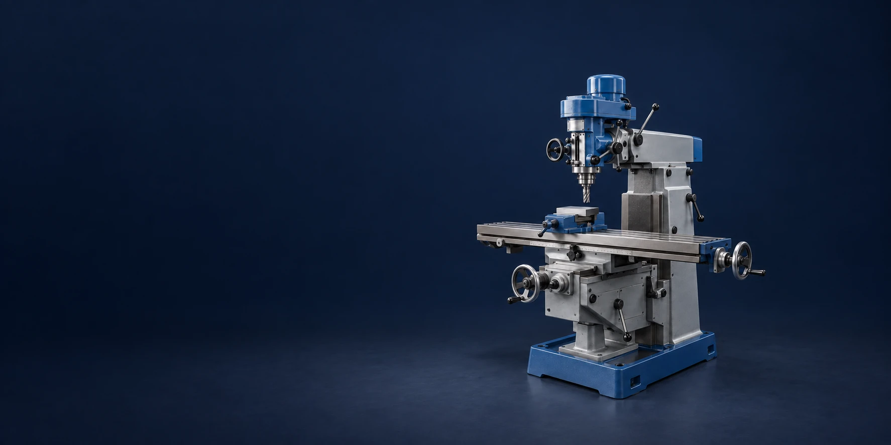
Header image: Illustrative vertical milling machine. AI-generated scene; not a photograph of vetcnc equipment.
The main parts of a milling machine
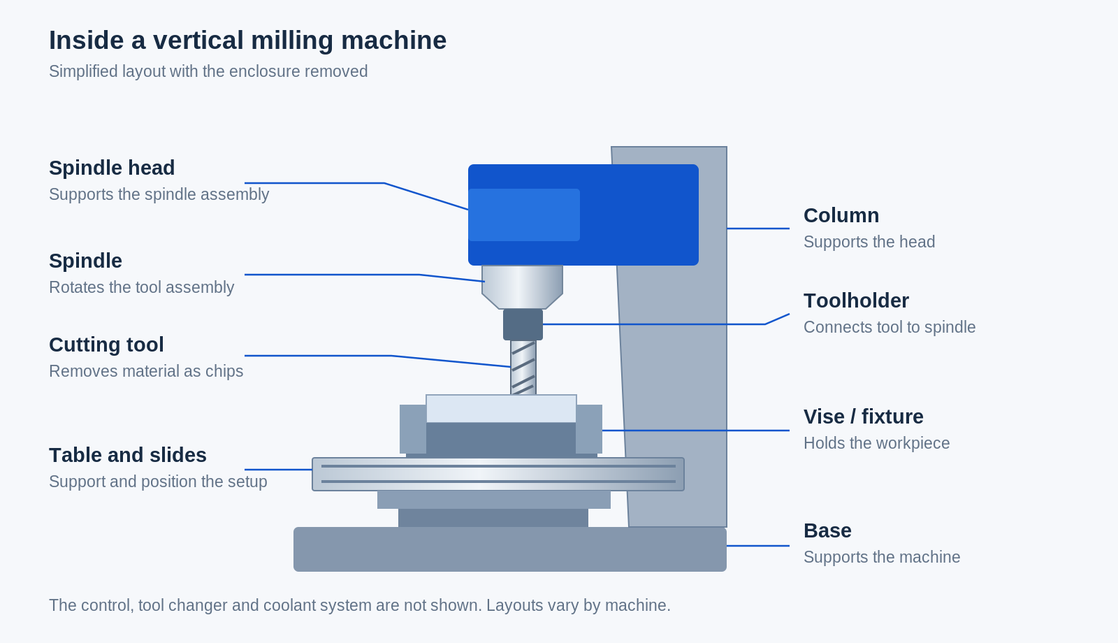
You don’t need to memorize every component in a machine manual. Start with the parts that hold the tool, hold the workpiece and move them relative to each other. On an enclosed CNC mill, some of these sit behind sheet-metal covers, so they’re easier to understand in a simplified diagram.
The spindle holds and rotates the cutting tool
The spindle is the rotating assembly in the machine head. It holds the cutter through a toolholder or collet, depending on the machine. The cutter is the replaceable part that touches the material; it isn’t the spindle itself. A machine might use an end mill for a recess, then exchange it for a drill or another tool.[1]
This distinction helps when a shop mentions a “spindle problem” or a “tool change.” One concerns the machine assembly. The other may simply mean swapping the tool needed for the next feature.
The table supports the part; the vise or fixture holds it
The workpiece usually isn’t attached straight to the bare table. A vise, clamps or a purpose-made fixture hold it securely. The fixture must resist cutting forces without blocking the areas the tool needs to reach.[3]
For our mounting plate, a vise might grip two opposite edges. But those edges can’t be finished while they’re hidden inside the jaws. The machinist has to think about that before starting, rather than discovering halfway through that the next cut is behind a clamp.
The base, column and slides support the movement
The base supports the machine, and the column supports the head or other moving assemblies. Slides and guideways constrain the travel to its intended directions. A saddle, where fitted, is an intermediate carriage beneath the table. The arrangement depends on the mill; not every machine has the same stack of moving parts.
On a knee-type mill, the knee raises and lowers the saddle and table. A quill provides axial travel for the spindle within the head, while a ram can reposition the head toward or away from the column. These are common features of manual turret mills, but they are not present on every mill. [14]
These components need stiffness as well as movement. The cutter pushes on the material as it cuts. If the tool, fixture or workpiece deflects too much, the result can be vibration, an uneven finish or a feature that doesn’t come out as intended.[10]
The control tells a CNC machine where to go
On a manual mill, the operator directs the movements using handwheels and, where fitted, powered feeds. On a CNC (computer numerical control) mill, motors carry out movements commanded by a program. The control screen also lets the operator check positions, offsets, programs and machine status.[4]
A digital position display alone doesn’t make a manual mill CNC. It can help the operator see where an axis is, but reading a position is different from having a program control the cut.
A tool changer saves the operator from stopping for every tool
Many CNC machining centers store several tools and exchange them automatically. Our mounting plate could use one cutter for the recess, a drill for the holes and a chamfer tool for specified edges. The machine can call up each tool without an operator manually replacing it between those operations.[5]
That is one reason you hear both “CNC mill” and “machining center.” A machining center commonly combines CNC control with automatic tool changing so it can perform several operations in a setup. The terms overlap in everyday shop conversation.
What moves when the machine starts cutting?
There are two movements to keep separate: the cutter spins, and the machine positions it relative to the workpiece. On a typical three-axis vertical mill, X and Y describe travel across the work area, while Z runs along the vertical spindle direction. Coordinating those movements lets the cutter follow a line, a circle or a changing surface height.[6][7]
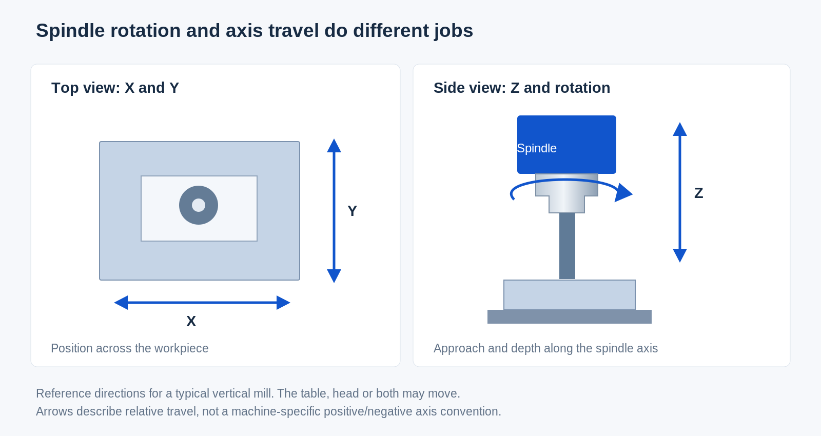
Here’s the slightly confusing bit: the cutter may appear to stay in the same left-to-right position while the table does the moving. That’s still controlled cutting motion. On other designs, the head moves, or movement is shared between the head and table. What counts is where the cutting edge is relative to the part.
To cut the plate’s shallow recess, the tool needs to reach the required depth and move across the area being cleared. To drill a mounting hole, it moves to the hole location and feeds along the spindle direction. These are different tasks using the same positioning system.
The machine also needs a reference point for the workpiece and information about each tool’s length. Work offsets and tool offsets provide those connections. A perfectly sensible program can still cut in the wrong place if the setup references are wrong.[3]
For a closer look at cutters, toolpaths and the order of operations, see how CNC milling works.
Manual or CNC? Vertical or horizontal?
These labels answer different questions. Manual or CNC tells you how motion is controlled. Vertical or horizontal tells you the spindle’s orientation. A vertical mill isn’t automatically CNC, and a CNC mill isn’t necessarily vertical.
On a vertical mill, the spindle axis is vertical. On a horizontal mill, the spindle axis is horizontal. Both can perform milling operations, but the spindle position changes how a part is presented to the tool.[1]
Some machines add rotary axes to turn or tilt the setup. That can bring another face into reach without taking the part out of its fixture. In 3+2 machining, the rotary axes position the part or tool before a cut; in simultaneous five-axis machining, orientation can change during cutting.[7]
You may also see gantry mills, which have a bridge-like arrangement spanning the work area. These layouts are used for large workpieces and broad tables, although a large platform can also carry many smaller parts.[8]
Don’t treat these names as a ranking from basic to best. For the mounting plate, most of the work is accessible from above. Adding more axes doesn’t automatically improve those features. It becomes useful when another face, an angled hole or the holding arrangement makes the extra movement worthwhile.
What can you make on a milling machine?
A mill is particularly useful when a part needs flat faces, pockets, slots, shoulders or a shaped outline. In a machining center, drilling, boring and tapping tools can add holes and threads alongside the milling operations. One machine can therefore carry out several kinds of machining; they don’t all have to be called milling.[2][11]
| Part or feature | What the machine contributes |
|---|---|
| Mounting plate or bracket | Flat mounting faces, outside dimensions, slots and hole locations. |
| Equipment housing | Internal recesses, cover seats and accessible openings. |
| Assembly fixture | Locating surfaces and accurately related holes for holding other parts. |
| Plastic guide block | Channels, mounting features and the surfaces that guide a moving component. |
| Contoured insert | Shaped surfaces produced by coordinated tool movement. |
The shape alone doesn’t tell you how easy the job will be. An open recess and a deep, narrow recess are both pockets, but the deeper one gives the tool less room and requires more reach.
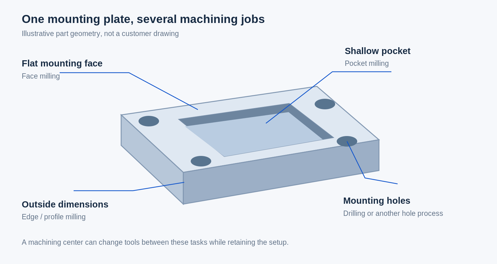
In our plate example, a machinist might prepare a reference face, machine the recess, make the mounting holes and finish the outside edges in a later setup. The exact sequence depends on the drawing and how the plate can be held. The useful thing to notice is that each feature needs both a suitable tool and access to the material.
Our CNC milled parts page shows more of these shapes together.
How is a mill different from a lathe or a drill press?
The easiest clue is the main cutting motion. In conventional turning, the workpiece spins while the cutting tool feeds against it. That arrangement suits diameters, shoulders and other features organized around the rotating part. In milling, the cutter supplies the rotation. A shaft can need both: turned diameters and a milled flat.[7]
A drill press mainly feeds a rotating drill into a workpiece along the spindle direction. A milling machine also supports controlled feeding across the workpiece for side-cutting operations. The similar appearance of an open mill and a drill press doesn’t make them interchangeable. Don’t assume a drill press is suitable for side milling; use equipment and tooling intended for the operation.
Then there’s the CNC router. Routers and mills can both move a rotating cutter through programmed paths. Many routers are arranged around sheet work, while mills commonly handle clamped blocks and machine components. But the boundary isn’t absolute: some gantry machines cut both metals and plastics. Machine construction, tooling and the job matter more than the label alone.[8]
What tells you whether a mill suits the part?
Machine size is a start, but “it fits on the table” isn’t the whole answer. A setup also needs room for the vise or clamps, the toolholder and the movements used to approach the work. Published machine specifications list axis travel, spindle-to-table clearance and table capacity separately for good reason.[9]
Travel and clearance
A plate might fit on the table while a particular edge is beyond the available travel. A tall fixture might leave too little space for a long drill. Think of the part, fixture and tool as one setup that must fit inside the working space, rather than checking the part’s dimensions in isolation.
The spindle and cutting conditions
Maximum rpm is only one spindle specification. Torque, power and the tool connection also affect what the machine can do. The highest speed printed in a brochure doesn’t tell you how well a particular cutter will work in a particular material.[9]
Aluminum, stainless steel and titanium need different cutting approaches. Alloy and material condition matter too, so “steel” is usually not enough information to plan the job. Our machining materials directory provides an overview of the material families used across the site.[12]
Support and tool reach
A small part can still be awkward if it has a thin wall or a deep feature. A long cutter is more prone to deflection, and a poorly supported workpiece can vibrate. The solution may involve a different fixture, a shorter tool or a change in orientation rather than a larger machine.[10]
For the plate, compare a wide, shallow recess with the same recess squeezed between thin walls. The outside dimensions haven’t changed, but the support available during cutting has. That’s why a useful machining discussion starts with the drawing, not just the machine model.
A few common questions
Can a milling machine drill holes?
Yes. A mill or machining center can hold a drill and position it at the required location. Depending on the hole, a different tool may follow to enlarge or finish it. Drilling a hole on a mill doesn’t change the operation’s name—it is still drilling.[11]
Can a mill make a round part?
Yes. A CNC mill can produce circular features by coordinating its axes. But a mostly cylindrical component may be a more natural turning job. A round shape alone doesn’t settle the choice; look at the rest of the features and how the part can be held.[11]
Does CNC mean the machine works without an operator?
No. A program automates the commanded movements, but someone still has to prepare the setup, load suitable tools, establish references and check the work. Automatic cycles don’t remove the need for trained operation or the machine’s guards and safety procedures.[13]
Start with the part you want to make
Once you’ve identified the spindle, the workholding and the axis movement, a milling machine becomes much easier to understand. In the mounting-plate example, the recess explains why the table and cutter need coordinated movement; the holes explain why tools change; the clamped edges explain why another setup may be needed.
You don’t need to arrive with a preferred machine model to discuss a component. A drawing, material, quantity and a clear explanation of what the part must fit will get the conversation much further. When you’re ready to discuss the actual component, our CNC milling service page covers that next step.
Sources and further reading
Manufacturer documentation and technical references for the descriptions above.
[1] Haas Automation — Mill Operator’s Manual: Introduction
[2] Sandvik Coromant — Milling knowledge
[3] Haas Automation — Mill Operator’s Manual: Part Setup
[4] Haas Automation — Mill Operator’s Manual: Control Display
[5] Haas Automation — Mill Operator’s Manual: Umbrella Tool Changer
[6] Haas Automation — Mill Operator’s Manual: Programming
[7] Autodesk — Fusion for Manufacturing: Milling, Multi-Axis and Turning
[8] Haas Automation — Gantry Series
[9] Haas Automation — VF-2: Technical Specifications
[10] Sandvik Coromant — Milling Vibration
[11] Sandvik Coromant — Milling Holes and Cavities/Pockets
[12] Sandvik Coromant — Milling Different Materials
[13] Haas Automation — Mill Operator’s Manual: Safety
[14] Bridgeport — Series I Milling Machines Installation, Operation and Maintenance Manual
Have a part in mind?
Share your drawing, material and quantity. Let’s talk through the requirements.
Prepare your RFQ →

