On this page
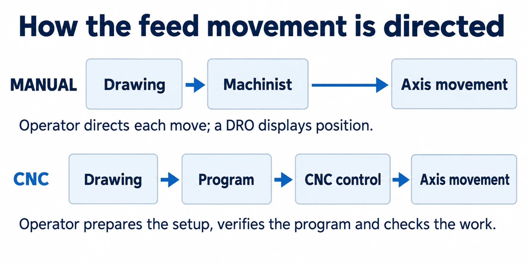
Manual milling puts the machinist in charge of each move. CNC (computer numerical control) milling uses a program to direct the machine’s movements. A manual mill can be a practical choice for a few straightforward cuts; CNC becomes especially useful when a job involves connected curves, many coordinates or repeated features. The difference is in how the work is controlled, not whether a motor turns the cutter. [1][2]
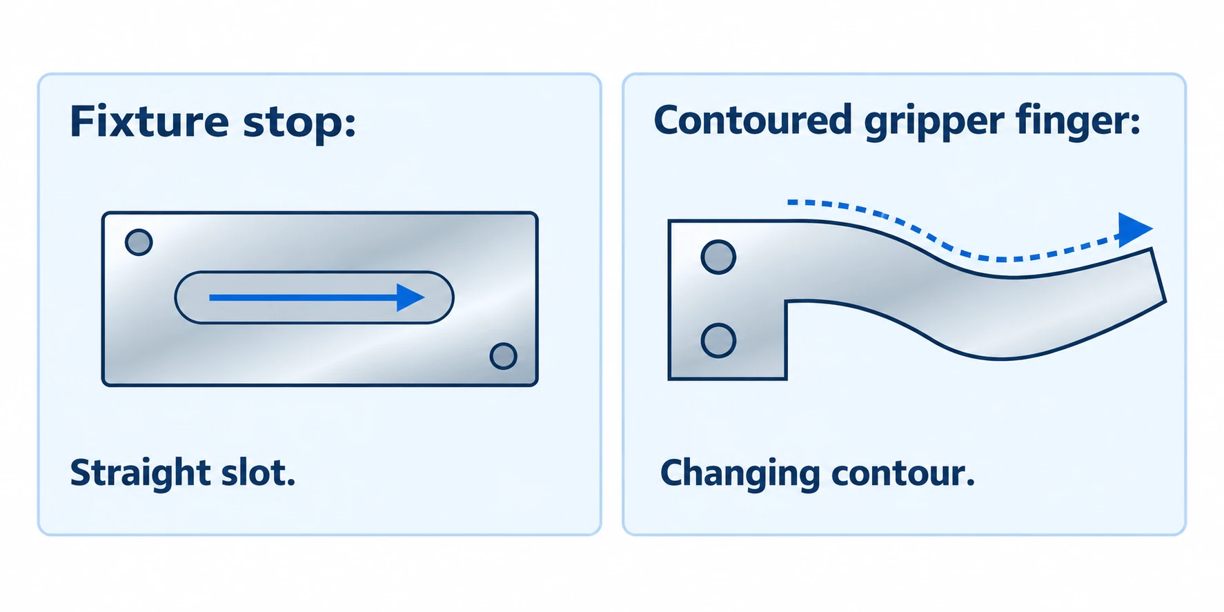
Take a fixture stop that needs one adjustment slot. An experienced machinist with a suitable setup may finish that job without preparing a CNC program. Give the stop a curved profile, add several hole positions, or ask for another batch next month, and saving the movements in a program becomes much more useful.
This article compares those working situations. For the cutting principles behind both methods, see how CNC milling works.
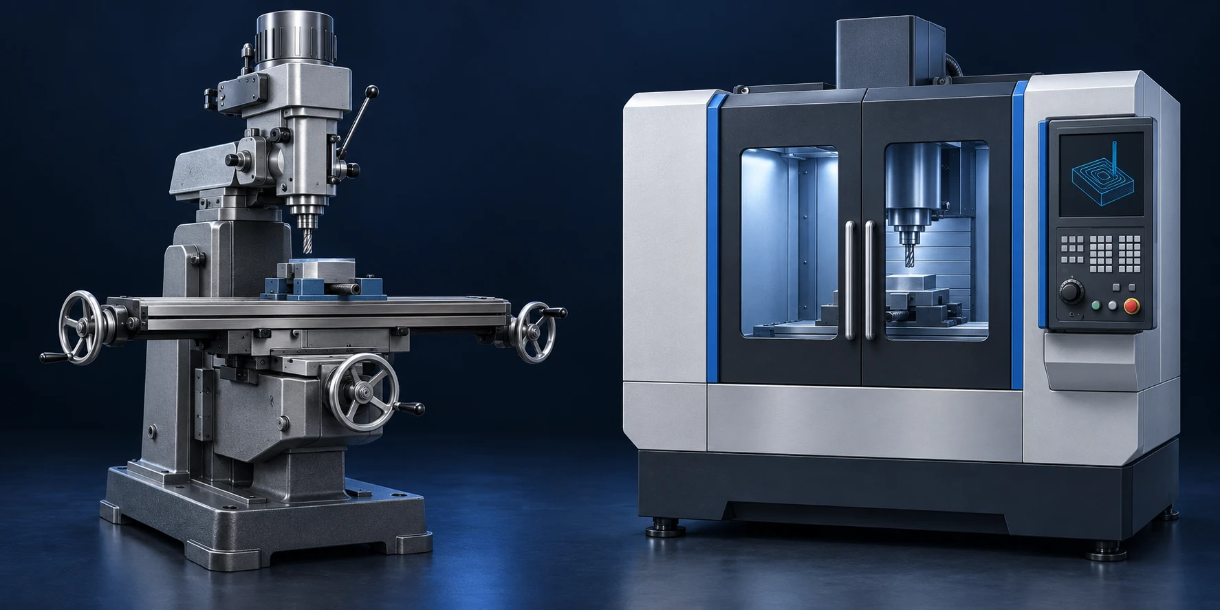
Header image: AI-generated concept illustration of a manual mill and a CNC machining center; not a photograph of vetcnc equipment.
Manual vs. CNC milling at a glance
| Question | Manual milling | CNC milling |
|---|---|---|
| Who directs the feed movements? | The machinist, through handwheels and any fitted power feeds. | The control follows programmed positions, paths and feeds. |
| What is a straightforward starting job? | A few accessible faces, slots or holes. | A contour, repeated feature pattern or a sequence worth saving. |
| What must be prepared? | Workholding, references, tools and the order of cuts. | Those same items, plus a suitable program and its verification. |
| How are curves produced? | Suitable accessories or coordinated manual methods; complexity adds work. | Coordinated axis motion follows programmed lines and curves. |
| What can be reused? | Fixtures, stops, notes and the operator’s method. | Fixtures and setup records, plus the program for the correct revision. |
| Where does operator attention go? | Directing movements and checking progress through the job. | Preparing and proving the process, loading, monitoring and checking parts. |
The mechanical work overlaps: both methods need a supported workpiece and suitable cutting tools. The main change is how much of the movement sequence the machine can carry out after it has been prepared. [2][10]
What changes at the controls?
Handwheels, power feeds and digital readouts
On a conventional manual mill, the operator positions the work and directs each cut. A handwheel moves an axis; a fitted power feed can carry it at a selected rate. The machinist still decides when to start, stop, change direction or move to the next feature.
A digital readout, or DRO, makes position easier to read. Instead of relying only on a graduated handwheel dial, the operator can see a position value relative to a chosen reference. The DRO reports movement; the operator still directs the cut. [1]
For the adjustment slot, the machinist needs to establish its position and depth, then direct the travel along its length. A power feed can assist with a straight pass. Adding a curve or a series of changing coordinates increases the amount of positioning work to manage.
A CNC program stores the sequence
A CNC program specifies movements and cutting conditions that the control can execute in order. The operator establishes the work location, loads the tools and enters or measures the relevant offsets. Those offsets connect the programmed positions to the real setup. [3]
For a repeated hole pattern, the control can return to a saved set of positions for successive operations. For a curved profile, it can coordinate axes to follow the contour. This is particularly useful when the required path would be cumbersome to reproduce by hand. [4]
Simple work can be programmed at the control using supported functions; more involved geometry may be prepared in computer-aided manufacturing (CAM) software. Toolroom CNC controls can simplify basic programming, so a one-off job need not involve a lengthy offline programming session. [5][6]
A CNC machine’s jog handle is used for positioning and setup too. Seeing a handwheel beside a screen doesn’t tell you that the machine is manual. Our guide to milling machine parts and motion explains the hardware in more detail. [6]
Where manual milling makes sense
A few direct cuts on a one-off part
Manual milling is worth considering when the geometry is easy to position and the job has little repeated movement. Examples include facing a small block, cutting an accessible straight slot or adding a small number of holes. These tasks need suitable tools and positioning, but do not inherently require computer control. [1][7]
Return to the fixture stop. Assume it is a rectangular blank, the slot is straight, and the required dimensions are within the shop’s demonstrated capability. Once the blank is held and the references are established, the machinist can work through a short sequence of moves. There may be little benefit in saving that sequence if only one stop is needed.
That advantage comes from the amount of preparation the particular job needs. A suitable CNC program already in the shop’s library would change the comparison. So would having the right fixture already mounted on one machine. For this stop, the useful question is which available setup gets the required cut done with less preparation.
A measured adjustment to a known feature
Sometimes a fixture needs a small change after a trial assembly. Suppose its clearance slot must be extended, and the engineer has specified the new endpoint and the surfaces that must remain untouched.
If the fixture can be held safely and the feature is accessible, a short manual operation may be convenient. The machinist can establish the reference, make the planned adjustment and measure the result. There’s no need to rebuild the entire manufacturing sequence just to discuss one additional cut.
The drawing change still belongs in the project record. Otherwise, the next fixture may be made to the old version and need the same adjustment. The adjustment should follow the approved change, including its new inspection requirements.
Manual work also remains useful for learning how positioning and cutting relate. Students can directly observe the effect of a feed movement or a change in depth. Training must include workholding, guarding and safe operation; familiarity with the handwheels is only part of the skill. [13]
Where CNC milling earns its setup time
Curves and coordinated movements
A curved gripper finger offers a different problem from the straight slot. Its working edge may blend a line into an arc, then into another curve. Following that shape calls for coordinated movement rather than a series of independent straight feeds.
CNC interpolation coordinates axes to produce programmed lines and arcs. With suitable CAM and machine capability, more involved profiles can be turned into a sequence of tool movements. The practical benefit is that the machinist can prepare and verify the shape, then run the same path again. [4][9][2]
Manual equipment can produce curved features too. A rotary table, for example, provides controlled rotation for circular work and indexing. But a convenient circular setup does not solve every irregular contour. Several changing radii or a freeform surface can make the manual route increasingly awkward. [7]
Here, CNC can be worthwhile even for one part. The reason is the path that must be followed, not the number of pieces ordered.
Repeated features and repeat orders
Consider a tooling block with many hole locations. A CNC drilling cycle can repeat at programmed coordinates, handling the approach, drilling and retraction for each location. The operator no longer has to position each hole by hand. [12]
The benefit grows when the operator would otherwise have to work through a long list of coordinates repeatedly. A saved sequence reduces that routine positioning work. A machining center equipped with an automatic tool changer can also move between tools within the cycle; CNC machines without that equipment still require manual tool changes. [5]
For a later order, keep the program with its drawing revision, fixture information, tool list and setup references. A file called “final.nc” leaves too much to guess. The operator needs to reconstruct the setup as well as reload the program. [3][9]
Manual batches can benefit from stops, fixtures and organized operation sheets as well. The comparison is the actual amount of positioning, handling and checking that remains for each part, rather than a claim that manual work starts from zero every time.
Which method is faster or cheaper?
Separate preparation from the work repeated on every part. Programming and proving a new CNC job can take longer initially, while a reusable cycle may reduce the repeated time. Manual work can have a short preparation stage for a simple feature but require more direct handling as the quantity grows.
The following example uses invented times to show that relationship. Assume both routes have already been judged capable of meeting the same drawing, and that the per-part figures include the same handling and checking scope.
| Illustrative shop time | Manual route | CNC route |
|---|---|---|
| Preparation for the batch | 30 minutes | 90 minutes |
| Repeated work per part | 20 minutes | 8 minutes |
| Total for 1 part | 50 minutes | 98 minutes |
| Total for 5 parts | 130 minutes | 130 minutes |
| Total for 20 parts | 430 minutes | 250 minutes |
For either route, total shop time = batch preparation + (quantity × repeated time per part). In this example, the CNC route needs 60 extra minutes of preparation and saves 12 minutes per part. At five parts, those differences balance. Change the program, fixture or cutting task, and the crossover changes too.
This is a comparison of time, not a price quote. A shop’s price also reflects different labor and machine costs, material, tooling, inspection and any finishing work. If loading or preparation overlaps with another activity, elapsed delivery time will differ from a simple sum of hours. A lower cycle time on its own doesn’t answer either question.
For a real order, compare the same quantity and scope. In particular, check whether one quote includes fixture preparation and the other assumes it already exists. Our CNC machining cost and quote-comparison guide covers those differences without prescribing a fixed batch size for switching methods.
Accuracy and finish: what does CNC actually improve?
CNC offers direct control over programmed positions and coordinated paths. That is especially valuable when several features must follow the same sequence or when a contour would be difficult to generate manually. It also makes a verified sequence easier to repeat. [4]
A skilled manual machinist can produce accurate work on suitable features. Both routes still depend on the physical cutting setup. A long tool can deflect, a thin wall can move, and wear in the machine can affect the result. Sandvik’s milling guidance identifies the cutter, holder, machine, workpiece and fixture as contributors to vibration. [10]
For the fixture stop, imagine that the slot is consistently positioned correctly but finishes too narrow. Repeating the position isn’t enough: the tool size, cutting behavior and measurement need attention. Conversely, a slot can have the correct width but be placed incorrectly. Those two faults call for different corrections.
A DRO’s last digit and a CNC control’s smallest displayed increment are position-display details, not a guarantee of finished-part accuracy. The feature has to be measured with a method suited to its requirement. [1][6]
Surface finish also depends on the cutter geometry, feed and runout. A programmed feed helps make the movement consistent; a suitable power feed can help with a straight manual pass too. Changing the control method won’t compensate for a damaged cutting edge or an unstable setup. [10][11]
This is why a useful comparison names the feature: slot width, hole position, flatness or a specified surface finish. A single claim that one method is “more precise” leaves too much unexplained.
What the operator still needs to do
On a manual mill, the machinist directs the feed, watches the position and decides when to move to the next cut. Reading the drawing, selecting tools and checking progress are part of that hands-on work.
CNC shifts more of that work into preparation. Someone must create or review the program, establish offsets, verify clearances and prove the first run. Program graphics and simulation can help with checking, while the physical setup still has to match what was planned. [9]
Once the cycle is proven, some cuts can run without the operator directing every movement. Loading, tool condition, chips and inspection still need attention. An automated cycle should be monitored and operated according to the machine’s safety requirements; it is not a reason to bypass guards or leave an unproven process unattended. [8]
Which approach fits your part?
For a one-off stop with a straight slot, start by considering a simple manual setup. For a gripper finger with a changing contour, consider CNC even if the quantity is one. For a repeat batch with many positions, compare the benefit of a saved cycle and reusable fixture against the work required to prepare them.
Machine availability matters too. A technically faster cycle on a machine with a long queue may not deliver the first part sooner. The shop needs to consider its actual schedule alongside the process.
Keep the drawing’s required dimensions and surface conditions the same when comparing the two routes. Where a customer-approved process already specifies the equipment or method, follow that requirement. Otherwise, the shop should be able to explain its choice using the cuts on the part, rather than simply saying “CNC is better.”
For a component you want to manufacture, our CNC milling services page covers the part information needed for a machining discussion.
Questions about manual and CNC milling
Can a component use both methods?
Yes. A shop may use a manual operation to prepare or adjust a feature and CNC to generate the rest of the geometry. The setup plan needs to carry the references between operations. The finished component is checked against the same drawing regardless of how those operations are divided. [3]
Does CNC milling always need a 3D CAD model?
No. Simple features can be programmed from dimensions using the control’s supported functions or a written program. A suitable computer-aided design (CAD) model becomes more valuable for complex profiles and surfaces. The model and drawing should agree on the revision and any dimensions the machining plan uses. [2][5]
Are toolroom CNC mills a separate process?
They use CNC milling, but their controls and layouts may emphasize easier setup and short-run work. Some support manual-style positioning alongside programmed machining. For a small job, look at how that particular control and setup will be used rather than forcing every machine into a strict “manual only” or “fully automated” category. [3][5][6]
Technical references
The sources below support the technical descriptions. Example jobs and the time comparison are illustrative, not customer production records.
[1] Sherline Products. Manual mill with a digital readout.
[2] Haas Automation. Mill Operator’s Manual: Programming.
[3] Haas Automation. Mill Operator’s Manual: Part Setup.
[4] Haas Automation. G02/G03: Circular Interpolation.
[5] Haas Automation. Toolroom Mills: controls and configurations.
[6] Haas Automation. Mill Operator’s Manual: Control Display.
[7] Sherline Products. Manual rotary table: rotation and indexing.
[8] Haas Automation. Mill Operator’s Manual: Safety.
[9] Haas Automation. Mill Operator’s Manual: Operation and graphics checks.
[10] Sandvik Coromant. How to reduce vibration in milling.
[11] Sandvik Coromant. Milling surface generation.
Have a part in mind?
Share your drawing, material and quantity. Let’s talk through the requirements.
Prepare your RFQ →

