On this page
The main difference between vertical and horizontal milling is the spindle orientation. A vertical milling machine has a spindle axis that is upright in its basic configuration; a horizontal milling machine has one that lies horizontally. Both can make accurate parts. The useful comparison is how each arrangement handles access, chips, workholding and the amount of handling between cuts. [1][2]
A mounting plate with a shallow pocket and a few holes looks straightforward. Clamp it flat, bring a cutter down from above, and most of its features are within reach. Now give that part ports on three sides and a bore that has to line up with a hole on the opposite face. The cutting isn’t necessarily the difficult bit anymore. Holding the part and getting at each face can become the bigger job.
For the cutting process behind both layouts, start with our guide to how CNC milling works. Here, we’ll focus on what changes when the spindle approaches the work from a different direction.
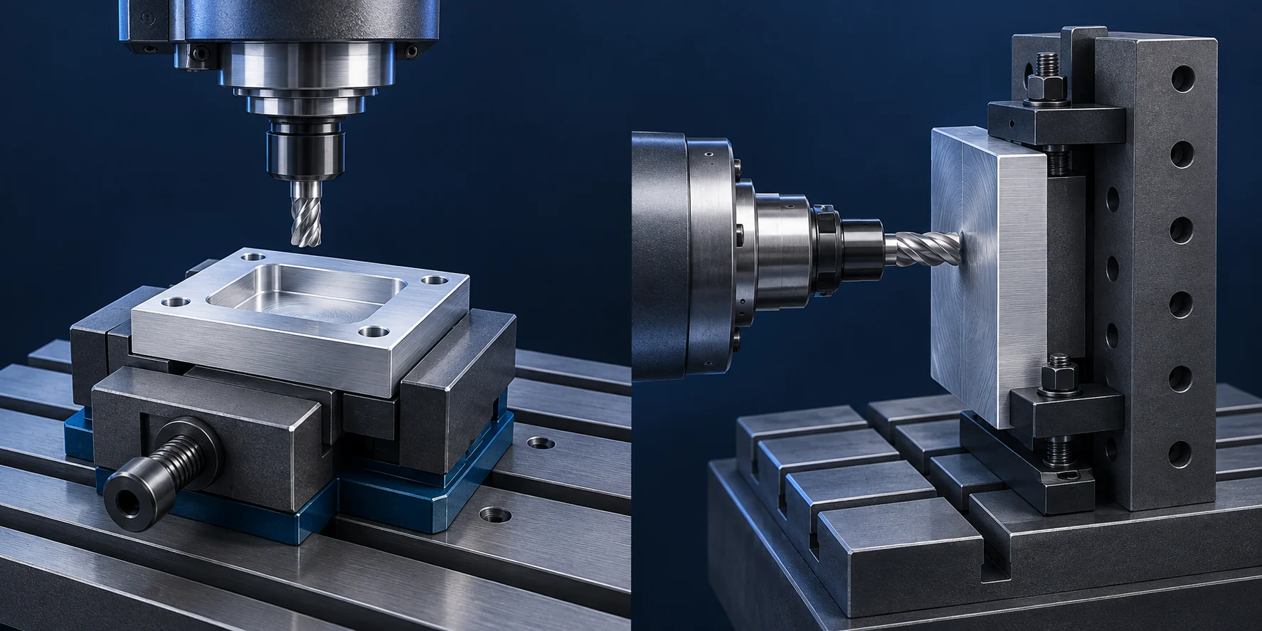
Header image: AI-generated illustration of vertical and horizontal milling setups; not a photograph of vetcnc equipment. Fixtures are simplified.
The difference starts at the spindle, not the table
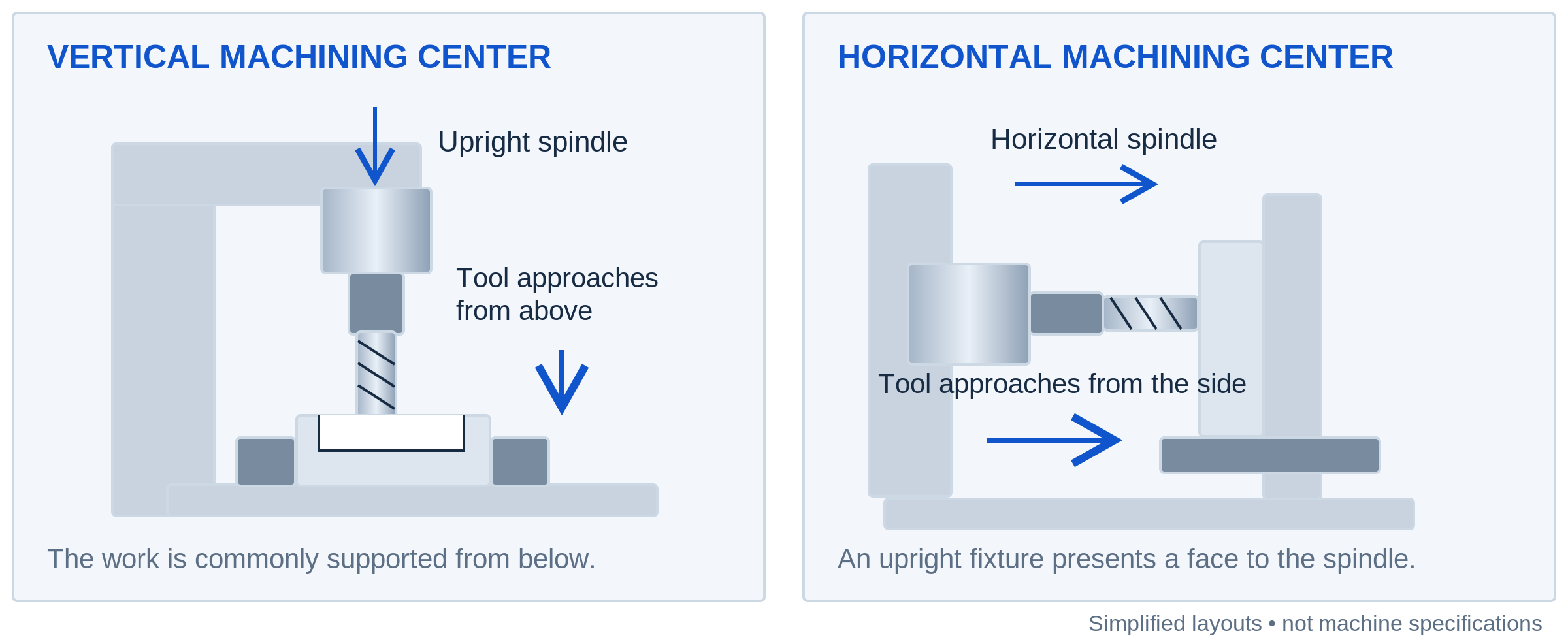
On a typical three-axis vertical machining center, or VMC, the cutter points down toward the work. A part held flat on the table presents its upper face to the tool. The tool can cut a pocket, drill holes or follow the outside profile without changing that orientation. Getting to the underside or a side-facing hole usually calls for another arrangement. [2]
On a horizontal machining center, or HMC, the spindle approaches from the side. The work may sit on an upright fixture, with the face being cut pointing toward the spindle. A suitably equipped rotary table can turn another face into position. ‘Vertical’ and ‘horizontal’ describe the spindle arrangement—not whether the machine can move only up and down or only sideways. [1][4]
You’ll also see conventional horizontal mills with disc-shaped or slab cutters mounted on an arbor, sometimes with support at the outer end. That is a useful arrangement for certain open slots and gang-milling jobs, where several cutters work together. It isn’t the only meaning of horizontal milling. A modern HMC can change between end mills, drills, face mills and other tools rather than relying on one arbor-mounted cutter. [3][6]
Need a refresher on the hardware? Our article on milling machine parts, motion and uses explains the spindle, table and workholding without assuming you already know the machine.
Vertical vs. horizontal milling at a glance
| What changes | Typical vertical arrangement | Typical horizontal arrangement |
|---|---|---|
| Tool approach | From above the work | From the side of the work |
| Convenient starting shape | Plate, open pocket or part with features on one main face | Block or housing with features on several accessible faces |
| Workholding | Vise, fixture plate or shaped jaws; a rotary can add access | Upright fixture or tombstone, often on an indexable table |
| Chip behavior | Upward-facing pockets can retain chips | Side-facing pockets often give chips a downward exit |
| Loading between cycles | Manual loading, robot loading or a pallet system, depending on the machine | Pallet exchange is common on production HMCs, but not universal |
| What the label does not tell you | Finished-part accuracy, spindle power or the complete setup plan | Finished-part accuracy, spindle power or the complete setup plan |
These are common arrangements, not fixed rules. A vertical machine with a rotary and pallet system may handle a multi-face production job very well. A horizontal machine can also make a simple part. Compare the proposed setup, not just the name on the machine. [1][2][8]
Workholding decides how many times the part comes out
A flat part can be pleasantly simple on a VMC
Take the mounting plate again. Suppose its pocket, mounting holes and outer profile can all be reached from above. A supported vise or fixture setup may give the machinist access to those features together. That keeps the first operation easy to explain: locate the blank, hold it, and machine the accessible features.
There may still be a second operation to finish the bottom or remove the material used for holding. But a second setup isn’t automatically a bad decision. For a small batch, a pair of uncomplicated fixtures can be more sensible than a much more elaborate arrangement intended to eliminate every flip.
An HMC can bring several faces to the same spindle
A tombstone is an upright, multi-sided fixture used to hold parts around its faces. On an HMC with suitable rotary positioning, the table turns the work toward the spindle. This can expose several sides while the part remains clamped. Haas’s large-frame HMC documentation, for example, describes a rotary-table option for access to four sides of a part or tombstone. [4]
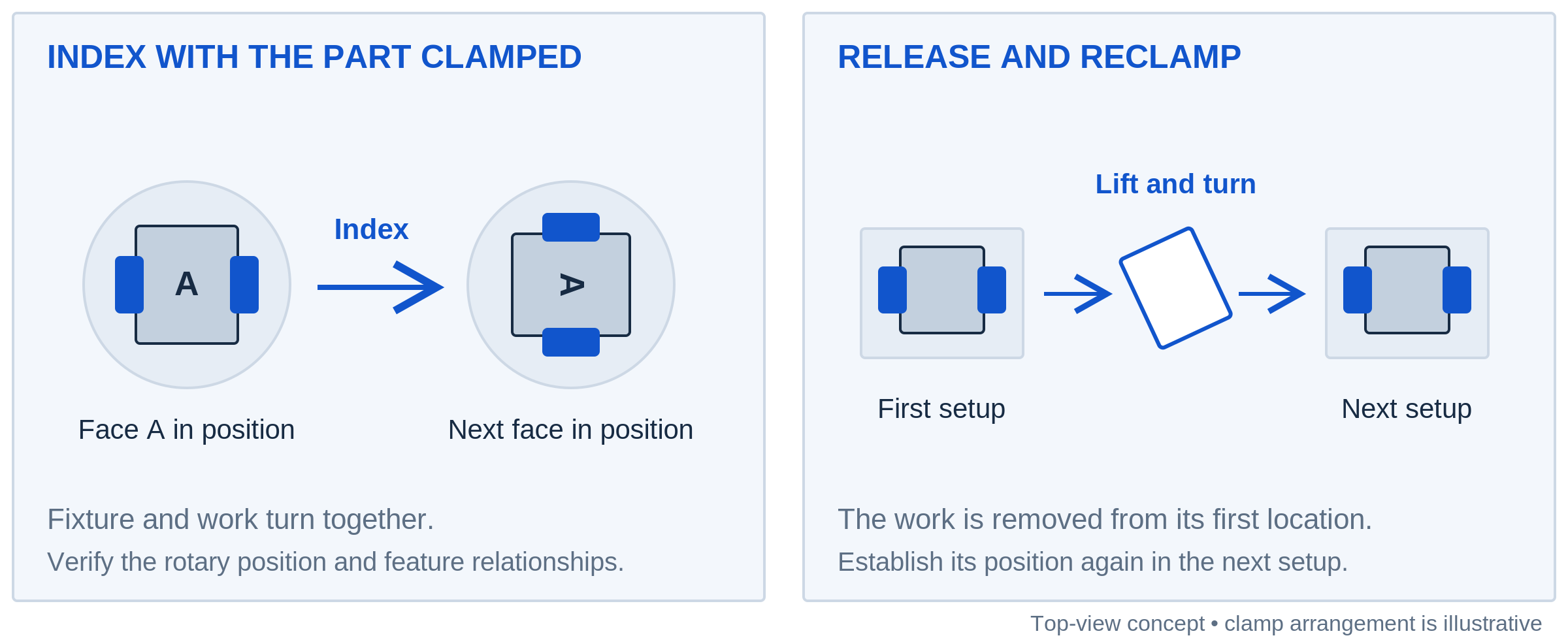
The advantage isn’t that the machine somehow knows every face perfectly. It’s that the machinist may avoid releasing and relocating the work between those faces. Indexing keeps the part clamped, but the rotary position and fixture alignment still need to be checked. Tool and work offsets connect the program to the real part. Keeping features in one clamping can remove some relocation steps; it does not remove the need to verify their relationship. [5]
There’s a catch: the fixture occupies space too. It can hide a surface, obstruct the holder or limit tool reach. A rotary table won’t make the clamped face accessible, and it won’t turn a four-sided arrangement into six-sided access. That is a geometry problem to solve in the setup, not a reason to assume either machine can finish the part in one go.
Chips behave differently when the pocket faces sideways
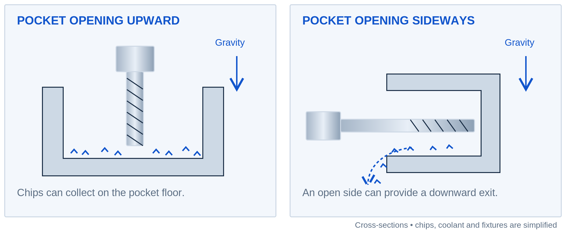
Think of an upward-facing pocket as a small tray. Once chips are inside it, gravity doesn’t lift them over the walls. Point that opening sideways and there may be a much easier downward path out. This is a consequence of the workpiece’s orientation: a vertical machine that tilts the part can change the situation too.
Good chip evacuation matters because chips left in the cut can be recut or jammed. Sandvik’s pocket-milling guidance specifically considers horizontal spindle arrangements for certain demanding cavity operations, alongside suitable coolant delivery. That doesn’t mean a horizontal spindle clears every pocket by itself. Blind passages, ledges and fixtures can still trap chips. [7]
The rest of the machine has to move the chips away as well. For example, the Haas EC-400 uses sloped enclosure surfaces, a conveyor and washdown nozzles as part of its chip-management system. That is a reminder to look beyond spindle direction: the exit route from the cut and the collection route through the enclosure both matter. [6]
For a shallow, open plate feature, this difference may change very little. For a deep pocket that sheds a lot of material, it deserves a proper discussion. Ask where the chips go during roughing—not merely whether the shop has coolant.
Tool reach and support matter more than a blanket accuracy claim
Turning a part toward the spindle can sometimes let the tool approach a difficult surface more directly. But neither layout guarantees a short, stiff tool assembly. A deep feature may still require extra reach, and an upright fixture can introduce its own clearance problems. Sandvik identifies the tool, holder, machine, workpiece and fixture as potential contributors to milling vibration, and recommends keeping the tool assembly as short and rigid as practical. [9]
That is why ‘horizontal machines are more accurate’ is too broad to be useful. Imagine one proposed setup using a short tool close to a solid support, and another using a long tool beside a poorly supported wall. Those details tell you more about the cut than spindle direction alone. The actual dimensional requirement still has to be checked on the finished feature.
Surface finish is a separate question. Tool geometry, feed and runout influence the texture left by the cutter; the machine’s orientation is not a surface-finish specification. A smooth-looking wall also doesn’t prove that its position or flatness meets the drawing. [11]
Two parts make the trade-off easier to see
The following are illustrative setup comparisons, not production records or fixed recommendations. They’re useful because the geometry changes while the basic cutting process stays the same.
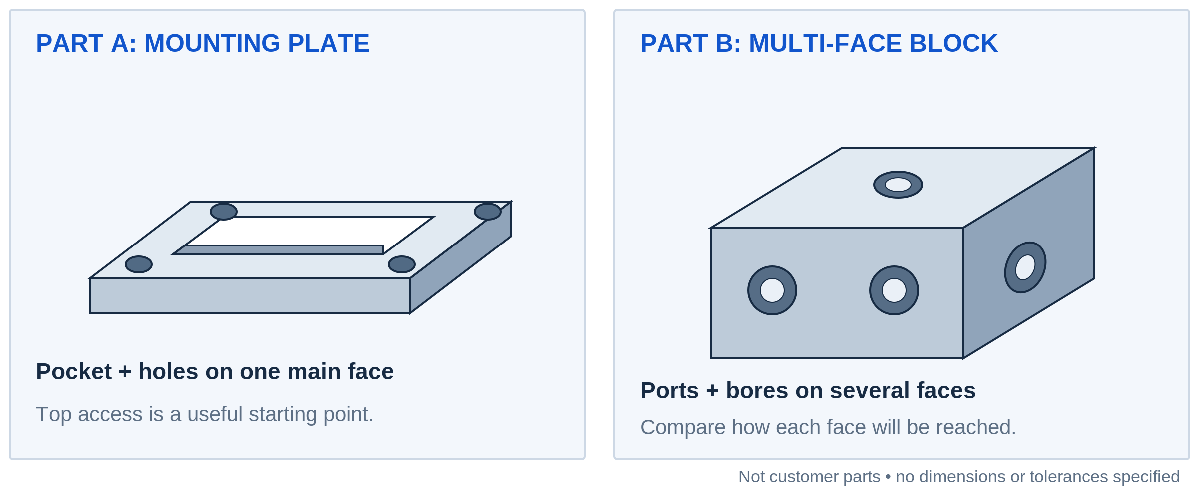
Part A: a plate with a pocket and four mounting holes
Picture a rectangular plate with a shallow recess, four through-holes and a finished outer profile. Most of the useful work is on one broad face. A vertical setup is an obvious starting point: lay the plate on suitable support, keep the clamps out of the cutting area, and work from above.
A horizontal machine could do the job, but standing the plate upright has to earn its place in the plan. Does the shop already have a suitable fixture? Will it load several plates on one pallet? Is there a repeat-order reason to make that investment? Without a useful answer, changing orientation may add work rather than remove it.
Part B: a block with ports on several sides
Now picture a block with bores, threaded ports and mounting faces on three sides. A fixed-orientation VMC may need several setups, or it may use an added rotary or another suitable arrangement. An HMC with appropriate indexing could bring those faces to the spindle while keeping the block located on the fixture.
Here the number of sides matters, but so do the relationships between them. A bore crossing another feature raises different questions from three unrelated mounting holes. The drawing should make those relationships visible. The machinist can then compare the practical routes, including how each one will be measured, rather than choosing a machine from the part’s general appearance.
The CNC-milled parts page shows the kinds of housings, brackets and multi-feature blocks that lead to these discussions. A similar shape is a useful starting point, not a promise that it uses the same fixture.
Batch size changes the value of a better loading arrangement
For an occasional one-off, fixture preparation can matter more than shaving a little time off each cycle. On a repeat order, the balance can shift. Once a fixture has been designed and proven, using it again may spread that preparation effort across more parts. That’s a cost relationship, not a universal volume threshold.
Pallet exchange adds another possibility: loading one pallet while the machine cuts work on another. Haas documents this arrangement on its vertical VC series, including both repeated jobs and different jobs on separate pallets. So automation is not a horizontal-only advantage. Whether it helps depends on how the loading, machining and exchange steps fit together. [8]
Here’s a simple example. Suppose one proven route removes 90 seconds of repeated handling per part. Over 200 parts, that is 18,000 seconds, or five hours of handling time. It isn’t automatically five hours off the delivery date: some work may already overlap, and the new fixture takes time to prepare. But it gives the shop a concrete saving to compare with that preparation effort.
The same logic explains why a higher machine-hour rate can still lead to a competitive part quote. Fewer handling steps, less repeated setup work or more parts per loading cycle may offset it. Equally, an elaborate pallet setup may make little sense for two simple prototypes. Compare the complete route and order quantity, not an isolated hourly rate.
A vertical machine can still machine several sides
Vertical versus horizontal is not the same comparison as three-axis versus five-axis. A vertical machining center fitted with a suitable rotary or tilting table can present additional faces to its spindle. Five-axis arrangements may position the part for fixed-angle cutting or coordinate rotary motion during the cut. Haas illustrates both approaches in its five-axis guidance. [10]
For a block with angled holes, that option might be more useful than a conventional horizontal arrangement. For a thin part, the decisive issue might instead be how it is supported. Once extra axes, specialized fixtures and loading systems enter the comparison, the question becomes less about two machine categories and more about two workable setups.
This is also why a drawing usually benefits from stating the needed result rather than prescribing spindle orientation. Specify the features, references and inspection conditions. Where a qualified process or contractual requirement does prescribe the equipment or route, keep that requirement explicit.
What to ask when a shop proposes one route over the other
Ask how the part is held and which faces are machined before it is released. Then ask what changes in the next setup. A useful explanation should point to the actual features on your drawing, not stop at ‘we’ll use the horizontal.’
For a deep cavity, ask how the tool reaches the bottom and how chips leave the cutting area. For a repeat order, ask whether the quote assumes a dedicated fixture, how that fixture is handled on later orders, and which quantities the price covers. For a close-fitting assembly, ask how the relevant surfaces are located and checked after all machining and finishing are complete.
You don’t need to write the machine program yourself. These questions simply make it easier to compare two proposed methods. For a specific part, our CNC milling service page explains what to include when sharing the drawing and requirements.
Questions about vertical and horizontal milling
Can a horizontal milling machine cut a flat surface?
Yes. Horizontal describes the spindle axis, not a restriction on surface shape. With suitable tooling and workholding, it can machine faces, slots, holes and other features. The question is whether that arrangement makes sense for the particular part. [1][3]
Does a vertical mill struggle with every deep pocket?
No. Depth is only one factor. Pocket width, tool reach, material, support and chip evacuation all matter. A horizontal approach may help in some cases, but it doesn’t remove the physical limits of the cutter or turn every deep feature into an easy operation. [7][9]
Is horizontal milling only worthwhile for high volumes?
No. Horizontal machine families include different work envelopes and configurations, not just pallet-changing production machines. A suitable fixture and a multi-face part can justify the approach on a smaller order. Repetition changes the economics, but there is no universal batch size at which every job should move to an HMC. [1][4]
Do I need to request vertical or horizontal milling in my RFQ?
Usually, it is more helpful to describe the required result and let the shop explain its route. Supply the drawing, material, quantity, finishing and inspection requirements; our CNC machining RFQ checklist explains what to include. Include any mandatory manufacturing-route restrictions separately, rather than assuming that the machine category alone defines quality.
Start with the faces you need to reach
For a plate with most of its features on top, a straightforward vertical setup may be all the job needs. For a block that keeps getting unclamped and turned, a horizontal arrangement or a rotary-equipped vertical machine deserves a closer look. And for a pocket full of chips, look at the escape path before asking for a faster spindle.
The useful decision is whether the setup reduces awkward access and repeated handling without creating another problem. To connect that decision with cutter selection, toolpaths and finishing passes, return to How CNC Milling Works: Cutters, Toolpaths and Part Features.
Technical references
The sources below support the equipment and machining explanations. The setup examples and time calculation in this article are illustrative, not results from a customer project.
[1] Haas Automation. Horizontal CNC Milling Machines.
[2] Haas Automation. VF-2: vertical machining center and rotary configurations.
[3] Sandvik Coromant. Groove or slot milling.
[4] Haas Automation. EC-1600: horizontal machine and rotary-table access.
[5] Haas Automation. Mill Operator’s Manual: Part Setup.
[6] Haas Automation. EC-400: tooling, chip management and pallet systems.
[7] Sandvik Coromant. Milling holes and cavities/pockets.
[8] Haas Automation. Pallet-Changing Vertical Machining Centers.
[9] Sandvik Coromant. How to reduce vibration in milling.
[10] Haas Automation. 5-Axis Machining Simplified.
[11] Sandvik Coromant. Milling surface generation.
Have a part in mind?
Share your drawing, material and quantity. Let’s talk through the requirements.
Prepare your RFQ →

