On this page
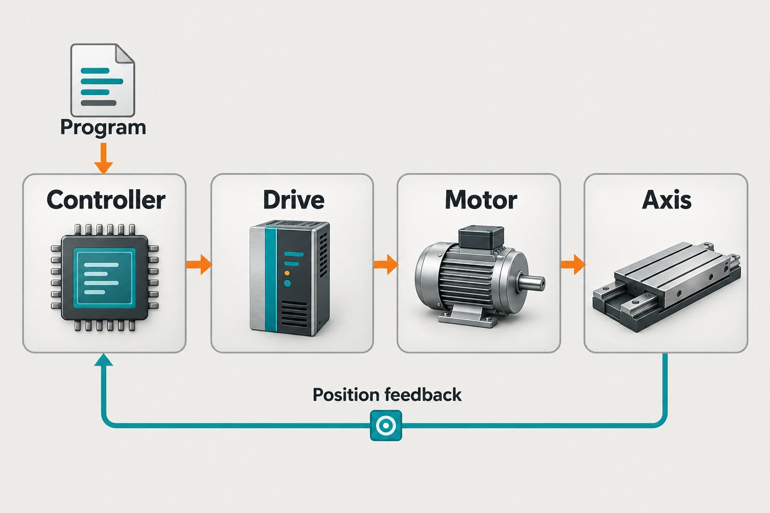
A CNC (computer numerical control) system turns a machining program into coordinated machine motion. The controller interprets the instructions and plans a path; drives supply controlled electrical power to motors; the motors move the machine axes. In a closed-loop system, position feedback helps the control compare commanded motion with measured motion. For the terminology and its history, the NC versus CNC comparison explains what changed when computers became part of the control.
Those are separate jobs. A correct program can be executed with a positioning error, while a perfectly tracked movement can still cut the wrong feature if the program or setup is wrong. Following a single move through the system makes that distinction easier to understand.
What each part of the control system does
The CNC controller combines computing hardware and control software. Its operator interface displays programs, positions, offsets and machine status. Behind that interface, program processing and motion planning determine what the machine should do next.
A drive is the power-control stage, not simply another name for the controller. In a servo system, it regulates motor operation through control loops. A motor then produces motion: a rotary motor may turn a ball screw to move a slide, while a linear motor can act directly on an axis. The placement of position, speed and current loops varies between control architectures.
Machine sequencing runs alongside this motion control. A programmable logic controller, or PLC, often handles auxiliary commands and status signals—for example, coordinating a tool-change sequence with its completion signals. This differs from calculating a continuous cutting path. Beckhoff’s auxiliary-function documentation shows how such commands can be synchronized with axis motion.
The program needs a physical reference
A program describes intended moves and machining actions, commonly using G-code and related commands. It may come from CAM software and a machine-specific postprocessor, or from manual or conversational programming. The control interprets instructions in the context of active settings, including units, coordinate systems and compensation. For example, absolute and incremental modes interpret positions differently: as a destination in the active coordinate system or as a distance from the current position. A coordinate alone is not a complete movement instruction.
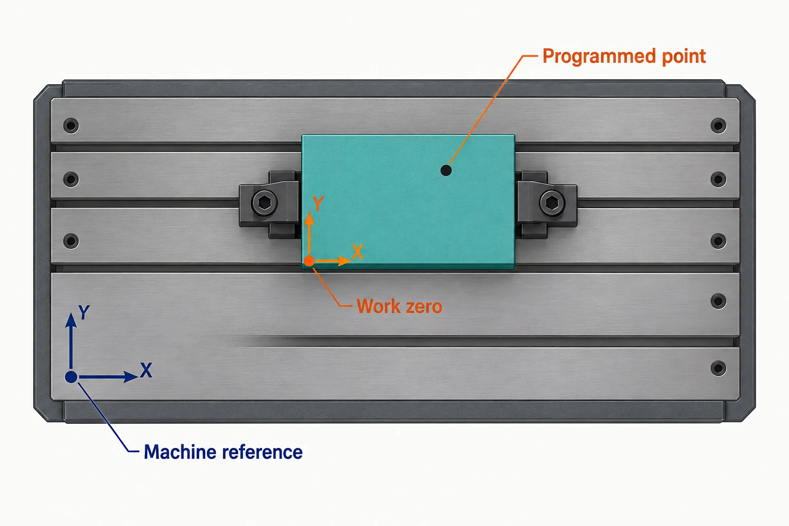
Machine coordinates refer to the machine’s reference system. Work coordinates locate the program relative to the part or fixture. A work offset connects these references, allowing the same part geometry to be programmed from a convenient work zero. Haas distinguishes these coordinate displays explicitly.
Tool offsets account for tool geometry; on a mill, tool length compensation relates the programmed tool location to the installed assembly. These offsets do not physically move the workpiece or change the cutter. They change how the control interprets the required machine position. Rotary configurations can also require a kinematic transformation to convert the desired tool-to-part relationship into individual axis commands.
If work zero is entered in the wrong place, the control may accurately follow a path shifted from the intended part location. Position feedback does not automatically recognize that the chosen origin was wrong. For the mechanical context behind these references, see milling machine parts and motion.
One path feed becomes several axis speeds
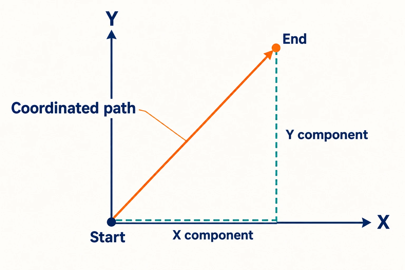
Interpolation determines intermediate positions along a specified path. For a straight X–Y move, both axes must make the appropriate share of the movement at the same time. Moving X to its endpoint and then moving Y would produce two sides of a rectangle, not the diagonal.
The planned movement becomes a stream of targets at successive control intervals. Depending on the architecture, the drive receives position or speed targets rather than interpreting the part drawing itself.
Consider an illustrative move with 30 mm of X displacement and 40 mm of Y displacement. Assume perpendicular linear axes, no rotation, a fixed tool orientation and a requested path feed of 500 mm/min. The following values describe the constant-speed portion, if the machine can reach it:
| Quantity | Calculation | Result |
|---|---|---|
| Path length | √(30² + 40²) | 50 mm |
| X speed | 500 × 30 / 50 | 300 mm/min |
| Y speed | 500 × 40 / 50 | 400 mm/min |
The two axis speeds combine to give √(300² + 400²) = 500 mm/min along the line. They are neither added together nor each set to 500. During acceleration and deceleration, the speeds change together while preserving the displacement ratio. This is the principle described in LinuxCNC’s coordinated-motion documentation.
A circular path needs continuously changing axis contributions. The addition of rotary axes and alternative feed modes add further interpretation rules, so this two-axis example should not be used as a universal formula for five-axis or turning programs.
Why the machine slows down before a corner
A machine cannot change velocity instantly. The trajectory planner accounts for configured speed and acceleration limits; some systems also explicitly constrain jerk, the rate of change of acceleration. A short move may finish before it reaches the requested feed.
Look-ahead prepares upcoming program blocks while the current motion is running. It lets the planner anticipate changes instead of treating each endpoint as an isolated event. Haas describes this advance block preparation in its control documentation.
At a mathematically sharp corner, following the exact path requires a stop. A blending mode can maintain motion by rounding the transition within its configured path-deviation conditions. The trade-off is between path fidelity and continuous speed; available modes and their behavior depend on the control. LinuxCNC documents exact-path, exact-stop and blending behavior.
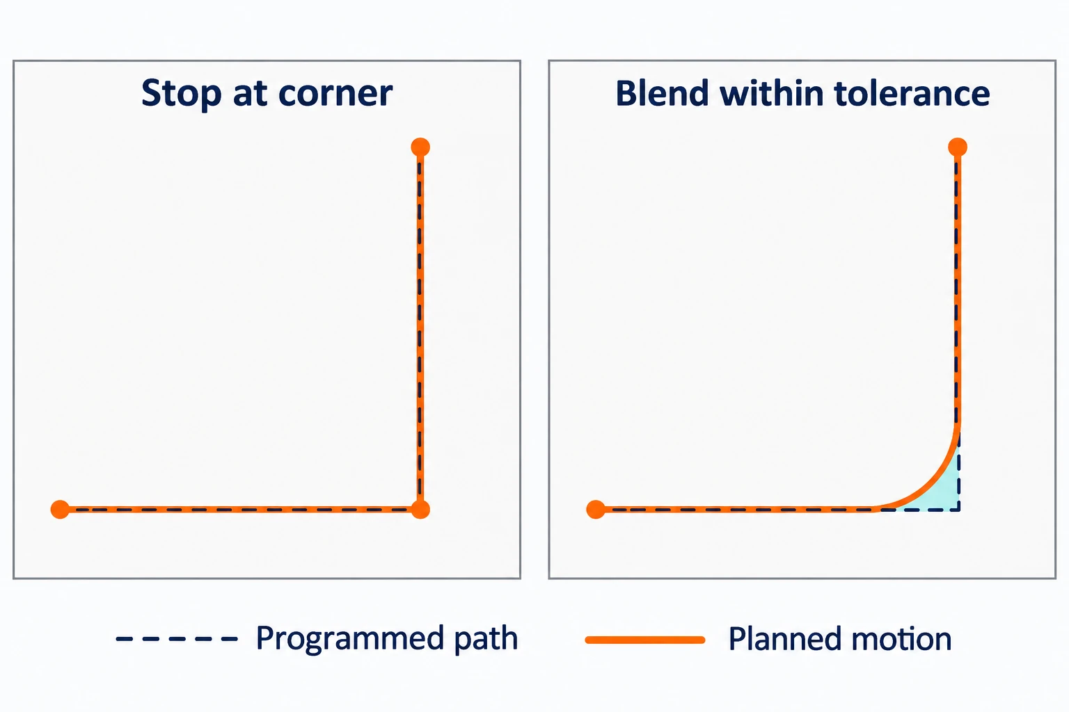
A path-blending tolerance is a motion-planning setting, not the finished part’s tolerance. Cutting forces, tool geometry and the rest of the process still affect the surface produced. Spindle rpm is also a separate quantity from linear feed. In feed-per-revolution and spindle-synchronized operations, travel is deliberately linked to spindle rotation.
Feedback measures motion at a particular point
In a closed position loop, the system compares a position command with a measured position and acts to reduce the difference. That difference is often called following error. It is not a direct measurement of the machined feature. The same distinction matters when reading machine accuracy specifications. The relevant loop may be closed in the controller or drive, depending on the system.
The sensor’s location determines what the measurement includes:
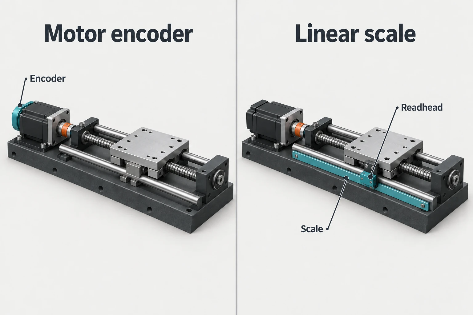
- Motor encoder: measures motor rotation. For a screw-driven linear axis, the control can infer slide position using the transmission relationship. Changes downstream of that sensor, such as ball-screw thermal growth, may not appear in the motor-position feedback.
- Linear encoder: measures slide position directly relative to its scale. When used to close the position loop, it includes the feed mechanics in that measurement instead of inferring travel only from motor rotation.
In machine-tool terminology, motor-based position feedback on a screw-driven axis is commonly called semi-closed loop; direct slide-position feedback is called closed loop or fully closed loop. Both use feedback. HEIDENHAIN explains this distinction. An encoder’s presence alone does not establish which signal the position loop actually uses.
Some CNC axes instead operate open loop, commanding motor steps without measuring the actual axis position in that loop. A lost step may therefore go undetected by the position command system. Stepper motors are not inherently limited to open-loop operation: closed-loop stepper arrangements also exist.
Separate the command, the motion and the part result
A useful first question is where a mismatch appears. A shifted program, an axis that cannot track its command and a cutter that deflects under load can all produce an incorrect part, but they call for different checks.
| Observation | What it may indicate | Useful evidence |
|---|---|---|
| The entire feature pattern is displaced | A program reference or setup offset may be wrong, even with good axis tracking. | Compare the intended datum, active work system, offsets and programmed locations. |
| Following-error alarms or unusual tracking deviation occur | Commanded and measured motion disagree; the cause may involve load, mechanics, feedback or the drive. | Correlate the alarm record and axis diagnostics with the move and operating condition. |
| Axis tracking looks normal but a wall, bore or surface is wrong | Tool geometry, deflection, workholding or thermal effects may lie outside the measured position loop. | Compare measured features with the tool condition, setup and cutting conditions. |
These are starting points for investigation, not diagnoses from appearance alone. Even direct slide measurement does not measure every movement between the cutting edge and workpiece. Inspection of the relevant part features closes a different information gap from axis feedback.
The CNC system establishes and follows a commanded motion. Understanding what was commanded, where motion was measured and what was actually cut provides a clearer explanation of a machining result than treating the controller as a single source of “accuracy.”
Frequently asked questions
Is a CNC controller the same as a CNC system?
The controller is the computing and control portion. “CNC system” can refer more broadly to the controller, interfaces, drives and feedback working together. Product terminology varies, so check which functions and hardware a description includes.
Does the CNC controller read a CAD model directly?
Usually it executes a machining program rather than interpreting an unprepared CAD model. CAM and a suitable postprocessor commonly produce that program. Some controls offer integrated or conversational programming, but geometry still has to become defined machining actions.
Does closed-loop control guarantee an accurate part?
No. It controls motion using the feedback available to that loop. Incorrect offsets, cutter deflection, workpiece movement and other process effects can still produce a wrong feature. Axis feedback and part inspection answer different questions.
Why can the actual feed be lower than the programmed feed?
Acceleration limits, short segments, corners, path-control settings and feed overrides can reduce actual speed. The requested feed is not a promise that the machine will maintain that speed throughout every move.


