On this page
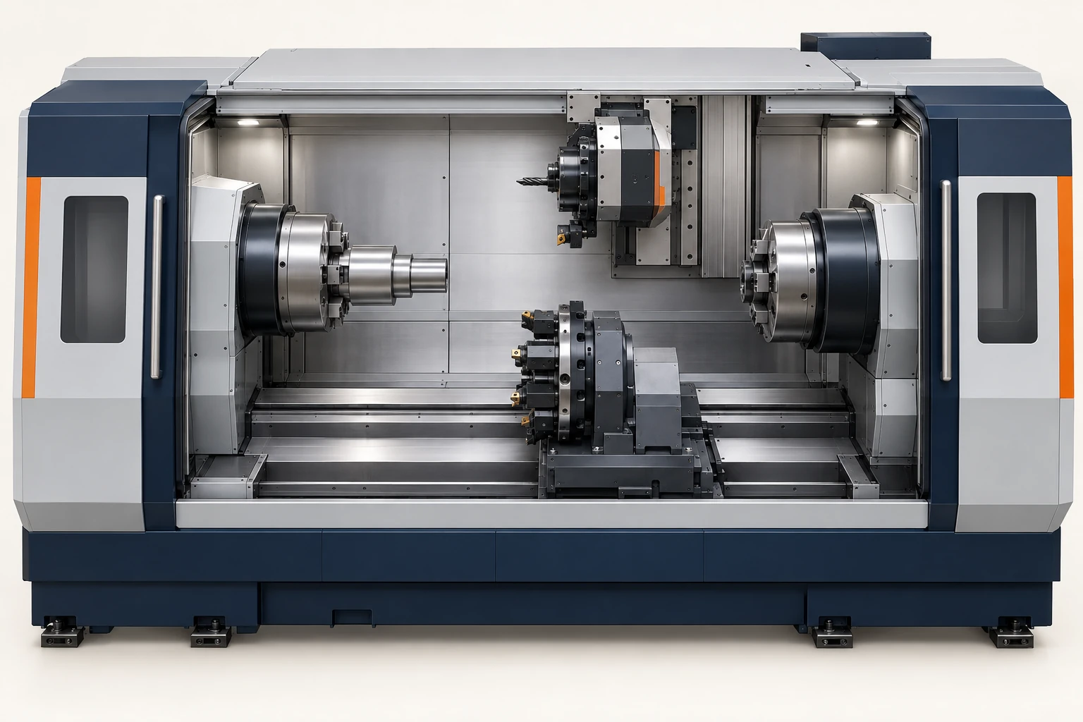
A 6-, 7- or 12-axis CNC description tells you how many axes are being counted, but the number alone does not identify the machine layout or the axes coordinated in one cut. A six-axis milling arrangement can combine three linear slides with three rotary-head axes. A seven-axis lathe can distribute its axes between main- and sub-spindle systems. A larger total can include several independently moving tool systems.
Start with the named machine and configuration. Its axis list explains what the number means—and whether the extra motion changes tool access, supports another operation or moves an automation device.
Separate the machine total from the cutting path
Three specification terms answer different questions:
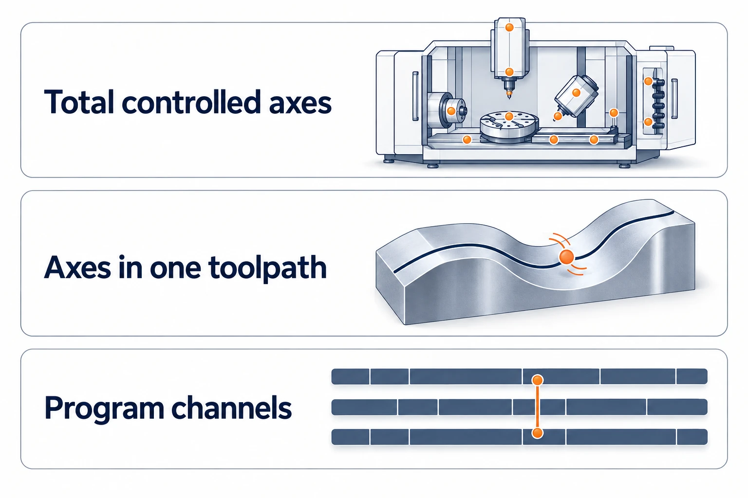
- Total controlled axes: the axes included in the stated machine or control configuration.
- Simultaneously controlled axes: the axes that can be coordinated together for a machining path, under the specified control functions.
- Paths or channels: separate program-execution groups that can organize different machining systems. They may run overlapping operations and synchronize when required.
These quantities are not interchangeable. FANUC’s controller specifications list maximum controlled axes, axes per path and simultaneously controlled axes separately. A controller’s maximum capacity also does not tell you which axes and options a particular machine builder has installed. The three-, four- and five-axis milling comparison explains the simpler case of linear and rotary axes controlling one tool-to-part relationship.
Likewise, two tools cutting at the same time are not necessarily performing one coordinated contour. One may be turning a diameter while another works on a different part held in the counter spindle.
When six axes describe a milling arrangement
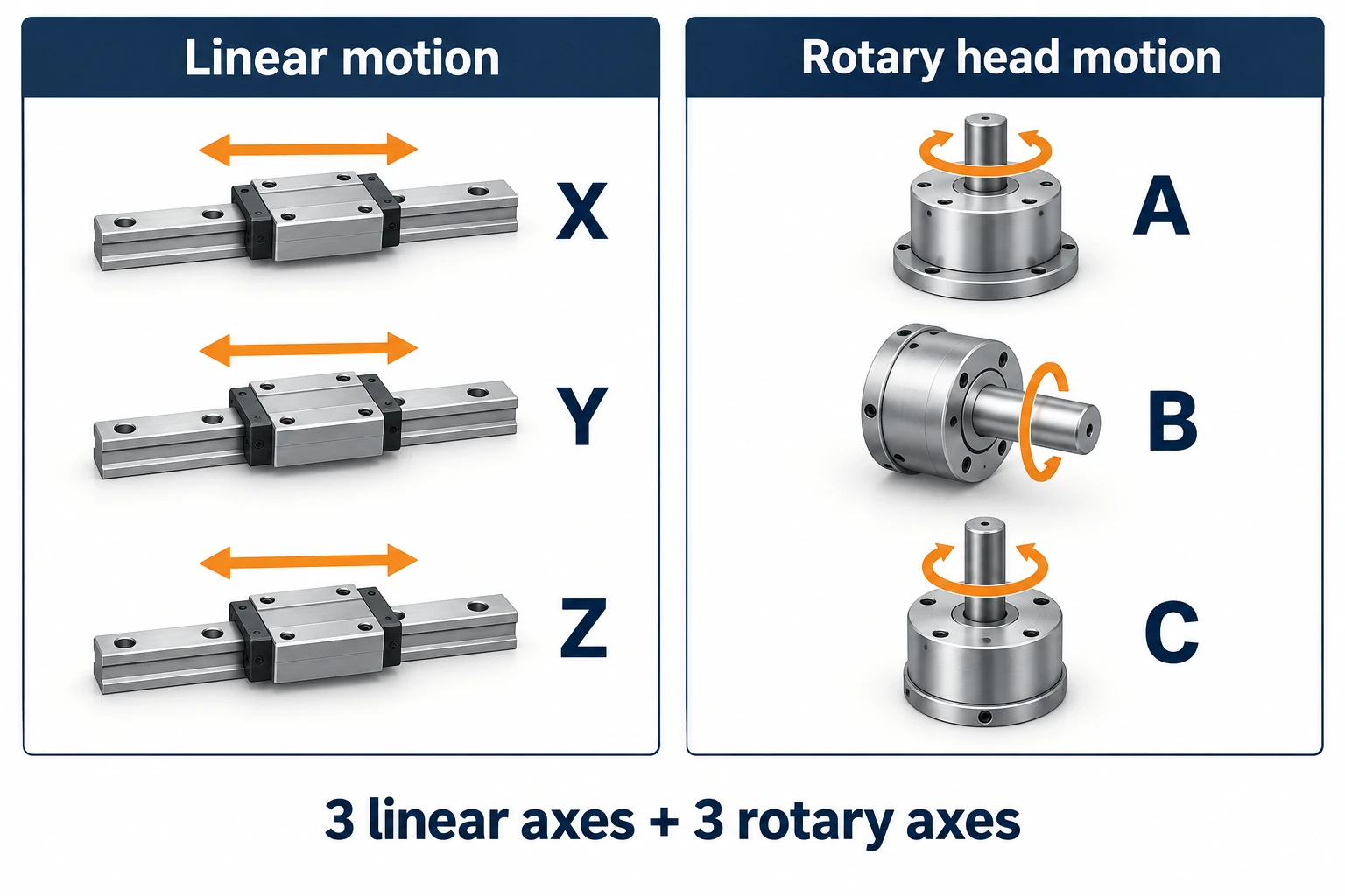
A concrete example is a Zimmermann FZH fitted with the M3ABC milling head. The FZH technical data sheet lists X, Y and Z linear motion and A, B and C rotary motion for that head. Counted as machining axes, that is three plus three.
The configuration matters: the same sheet also lists a different head with two rotary axes. It lists pallet-automation lifting and feeding axes separately, too. A six-axis machining description therefore need not include every controlled movement in the complete installation.
The extra rotary motion gives this head another way to establish its orientation. It is not a general promise that any six-axis machine reaches every undercut, finishes faster or holds tighter tolerances. The head arrangement and its working ranges still determine the available motion.
The cutter still removes material through ordinary milling operations. For that process background, see how CNC milling works. Here, the useful distinction is between the movements available for machining and the other movements included elsewhere in the equipment specification.
A seven-axis lathe can split its axes between two sides
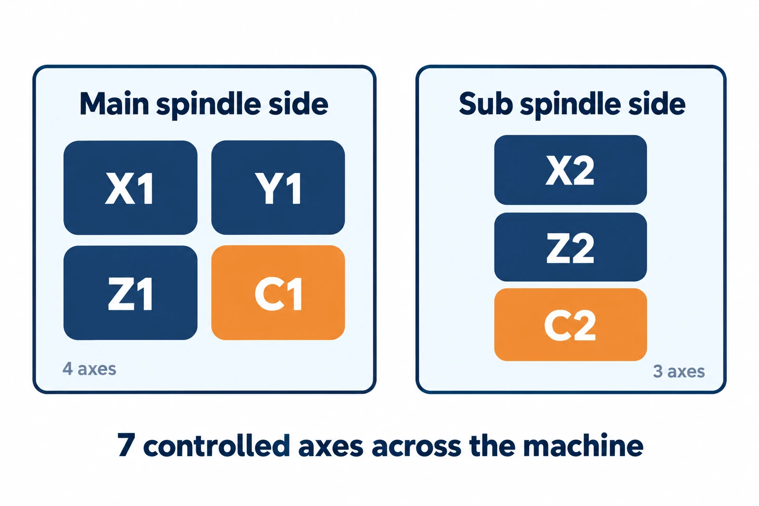
The Star SP-32 provides a clear answer to what “7-axis CNC” can mean. Its machine specification divides the axes as follows:
| System | Listed axes | What moves |
|---|---|---|
| Main spindle side | X1, Y1, Z1, C1 — four axes | X1/Y1 move the tool post; Z1/C1 belong to the main headstock. |
| Sub spindle side | X2, Z2, C2 — three axes | The sub-spindle system has two linear axes and a controlled rotary axis. |
The repeated X and Z letters matter: X1 and X2 are separate machine axes, not extra directions in space. C1 and C2 control spindle angular position. That is a different function from simply specifying spindle speed in rpm.
Star’s US specifications also state seven control axes across two paths: four on Path 1 and three on Path 2. They list synchronization functions separately. The total does not establish seven-axis interpolation at one cutter, nor does it describe a milling head with four rotary joints.
A robot’s six or seven axes use a different layout
A robot machining system can use similar numbers for a different mechanism. KUKA’s KR QUANTEC brochure lists six axes for the standard models shown. Those axes belong to the articulated robot, rather than a set of X/Y/Z machine slides plus a milling head.
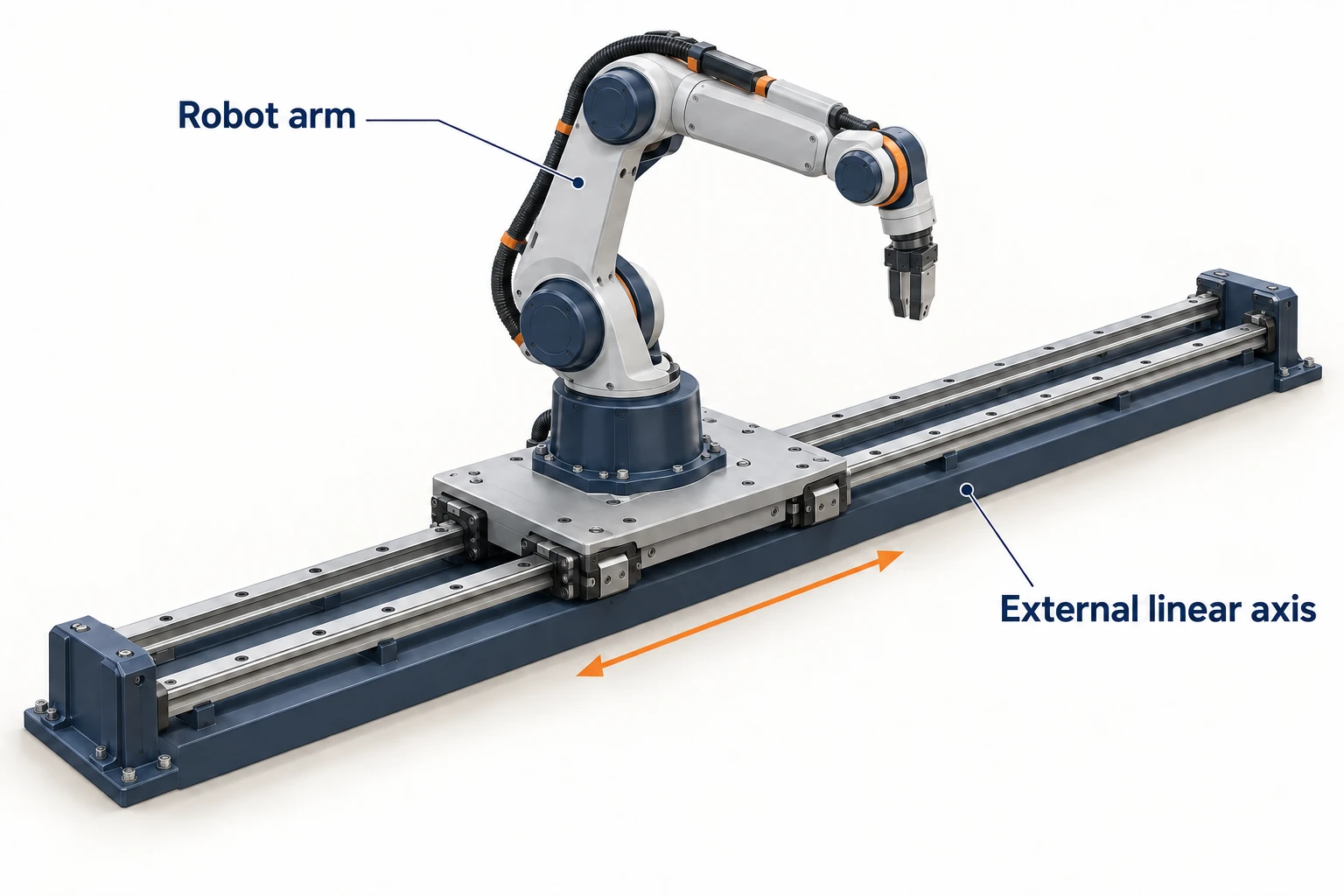
An external axis can enlarge the system count. The KUKA KL 5000 is a one-axis linear unit for compatible robots. A six-axis arm mounted on one such controlled track gives six robot axes plus one external axis; the added movement relocates the robot base.
But seven does not always mean an arm on a rail. KUKA’s LBR iiwa is itself a seven-axis robot. Read whether the description counts arm joints, external tracks or workpiece positioners. None of those counts, by itself, establishes the accuracy of a finished machined part.
Eleven and twelve axes can be distributed across tool systems
Higher counts become easier to understand when you look at a multitasking lathe instead of imagining more joints on one cutter.
Star’s SW-20 launch description specifies nine linear control axes and two rotary control axes, totaling eleven. It describes independently controlled tool posts that can overlap turning, drilling and milling. This is a Swiss-type automatic lathe with milling capability; the phrase “11-axis milling machine” alone does not identify its architecture.
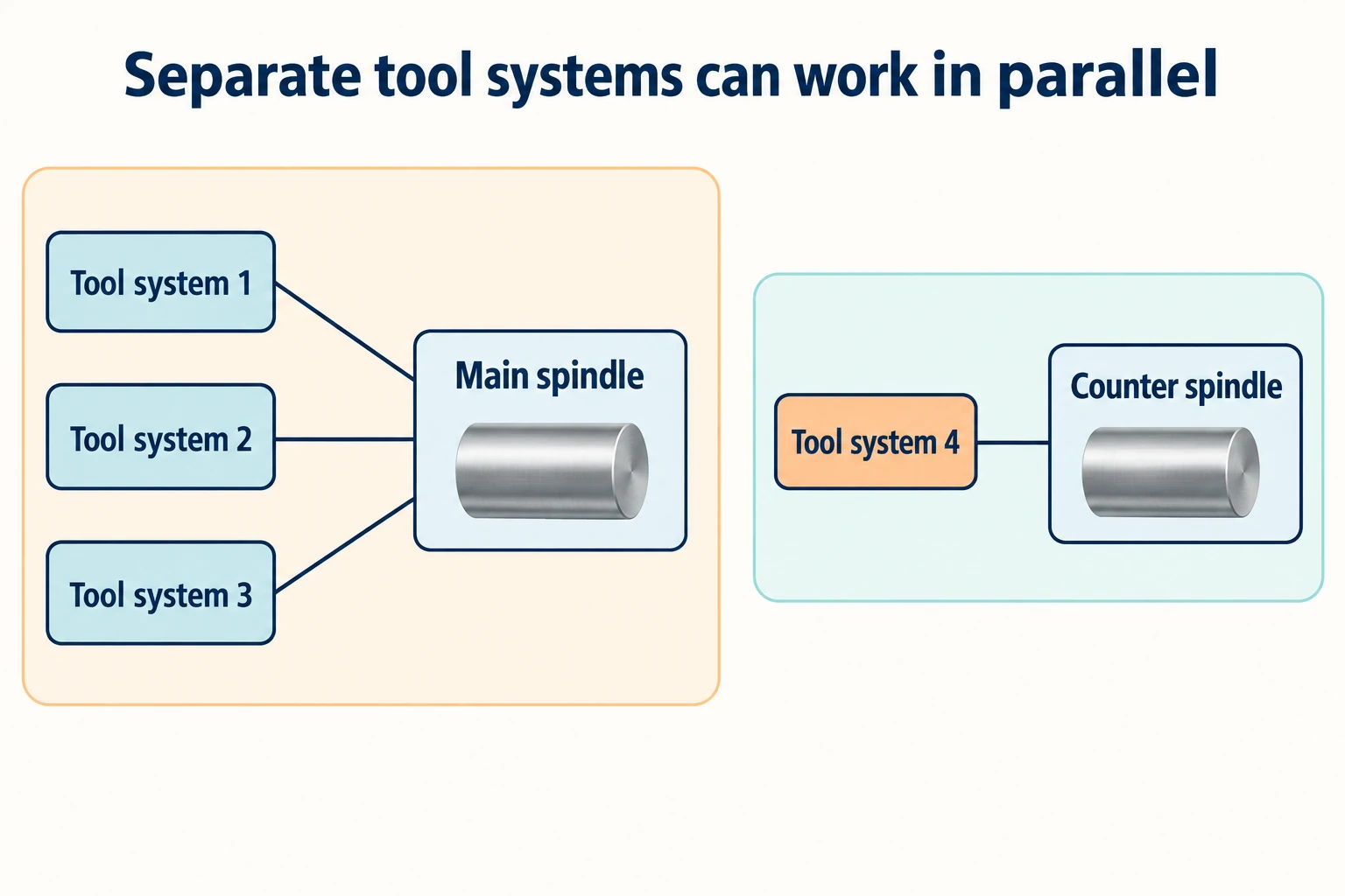
For another example, the Tornos EvoDECO specifications list ten linear axes and two C axes for the 20 and 32 models. Adding those categories gives twelve. The same table lists four independent tool systems and lists tool positions separately. Twelve axes does not mean twelve tools, or two six-axis milling heads.
Tornos describes three tool systems machining at the main spindle while a fourth works at the counter spindle. Here, the extra systems make parallel operations possible. That is distinct from changing one tool’s direction continuously along a surface.
Parallel work helps only where operations, tool access and timing permit it. A receiving spindle must be ready for a transfer; a tool system cannot start an operation that depends on unfinished work. The useful question is which operations can overlap and which must wait, rather than how many axes appear in the headline.
Turn an axis count into a useful machine description
Read an unfamiliar specification from the moving components outward. A short description can preserve much more information than “high-axis CNC.”
| Record | What it resolves |
|---|---|
| Machine model, head and configuration | Whether the number describes a mill, turning center, Swiss-type lathe or robot system. |
| Axis names and moving components | Which axes move tools, workholding, a second spindle or an external device. |
| Axes coordinated for the intended operation | Whether the needed contouring capability exists, independently of the whole-machine total. |
| Program paths, synchronization and operation sequence | Whether different systems can work in parallel, and where one must wait for another. |
| Separate tool and automation counts | Whether tool positions, driven-tool spindles or pallet movements have been mistaken for machining axes. |
For example, “a Swiss-type lathe with separate main- and sub-spindle systems, C-axis positioning and driven tools for cross-machining” tells you what sort of work the machine is arranged to do. A numerical label alone leaves those relationships unstated.
Then connect that layout to the actual features: the direction of a hole, access to the rear face or the opportunity to machine another feature while a different system is busy. Axis count is a useful entry point into that explanation. The component layout, coordinated motion and operation sequence finish it.
Frequently asked questions
Does 6-axis CNC always mean X, Y, Z, A, B and C?
No. That combination describes some milling configurations, including the FZH with an M3ABC head discussed here. Robot and multitasking-machine descriptions can count different mechanisms. Use the manufacturer’s axis list for the specific configuration.
Is a 12-axis CNC machine always two six-axis heads?
No. A machine can accumulate its axis total across several tool and spindle systems. The EvoDECO 20/32 example lists ten linear axes and two C axes alongside four independent tool systems.
What does “11-axis milling machine” mean?
The number needs a model and an axis breakdown. An eleven-axis machine may be a Swiss-type lathe that also performs milling, as the SW-20 illustrates. The phrase does not establish eleven-axis contouring by one milling cutter.
Does a higher axis count mean a more accurate part?
No. The count describes available controlled motion, not a finished-part tolerance. Tooling, workholding, the condition and calibration of the machine, and the machining process still affect the result. Accuracy must be evaluated against the part’s requirements.


