On this page
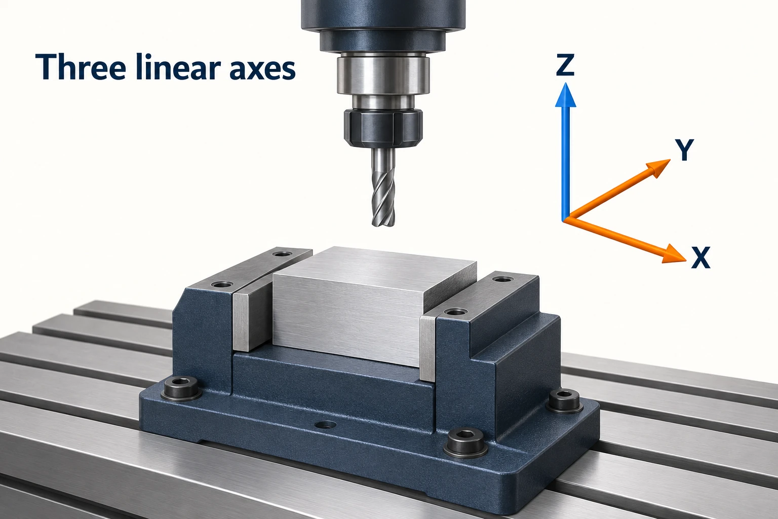
For conventional CNC milling, three axes position the tool relative to the part along X, Y and Z. A fourth axis adds one controlled rotation; a fifth adds a second. The useful difference is which feature directions the machine can reach while the workpiece stays clamped, and whether its orientation can change during a cut.
A 4-axis CNC machine can be an effective way to machine features around a shaft or present several faces of a bar to the cutter. Five-axis equipment offers more freedom to orient the part or tool, but that does not make every job faster, cheaper or more accurate. Start with the features that need cutting.
What the axis count actually describes
An axis is a controlled direction of motion. In this milling comparison, X, Y and Z are three perpendicular linear directions. For the cutting actions these motions produce, see how CNC milling works. The usual rotary names are A about X, B about Y and C about Z. A particular machine uses the rotary arrangement its design supports; “five-axis” does not mean it has all three rotary axes.
These are relative motions between the cutter and workpiece. The table may move, the spindle head may move, or both may move. Ordinary cutter rotation at the spindle’s cutting speed is not counted as an extra positioning axis here. Descriptions of 6-, 7- and 12-axis machines can count axes across several tool systems, so their totals need a different reading.
| Configuration | Controlled motion | What it changes for the part |
|---|---|---|
| 3-axis | Three linear axes | The tool can follow a three-dimensional path, while its axis direction relative to the clamped part stays fixed. |
| 4-axis | Three linear axes plus one rotary axis | The part or tool gains one family of orientations around that rotary axis. |
| 5-axis | Three linear axes plus two rotary axes | The tool-to-part orientation can change in two rotary directions, within the machine’s travel and clearance limits. |
Three-axis milling is not restricted to flat parts. A ball-nose cutter can follow an accessible curved surface by coordinating X, Y and Z. Autodesk’s machining overview includes complex molds among three-axis applications. The question is whether a suitable cutter can reach the surface with its orientation fixed—not whether the CAD model looks three-dimensional.
A fourth axis works around one rotary direction
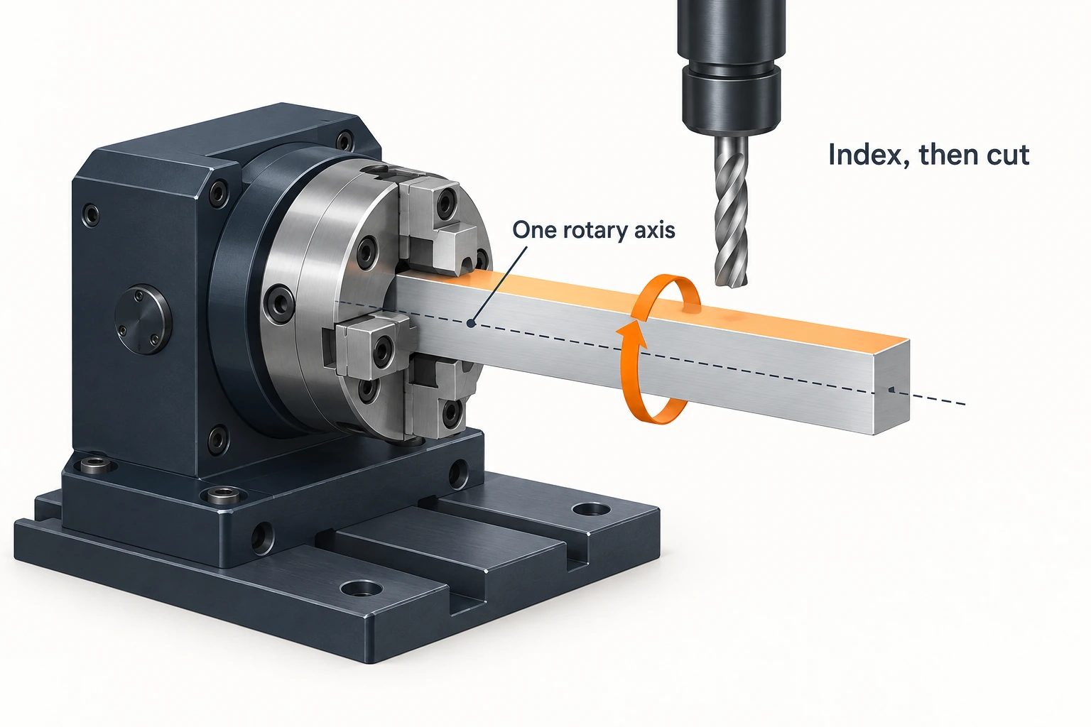
Consider a vertical mill with a horizontal rotary attachment whose centerline runs along X. This is an A-axis arrangement. A short square bar held along that centerline can be indexed so each longitudinal face points toward the vertical spindle. Holes or flats on those faces can then be machined without releasing and reclamping the bar.
Now add a hole that runs along the bar’s centerline, entering its end. Rotating the bar around X does not turn that hole toward a Z-oriented drill: its direction remains parallel to X. That feature needs another access route, such as a different setup or suitable additional tooling. One rotary axis does not provide every approach direction.
A four-axis mill can use that rotation in two distinct ways:
- Indexed, or 3+1, machining: rotate to an orientation, hold the rotary axis there, then cut using the linear axes.
- Simultaneous four-axis machining: coordinate rotary and linear motion during the cut, for example when following a feature that wraps around the workpiece.
The attachment and controller must support the intended mode. Haas’s rotary integration manual distinguishes its indexing-oriented semi-fourth-axis arrangement from a true fourth-axis connection that supports simultaneous interpolation. Adding a rotary device alone does not establish what coordinated motion the system can run.
A fifth axis adds another orientation choice
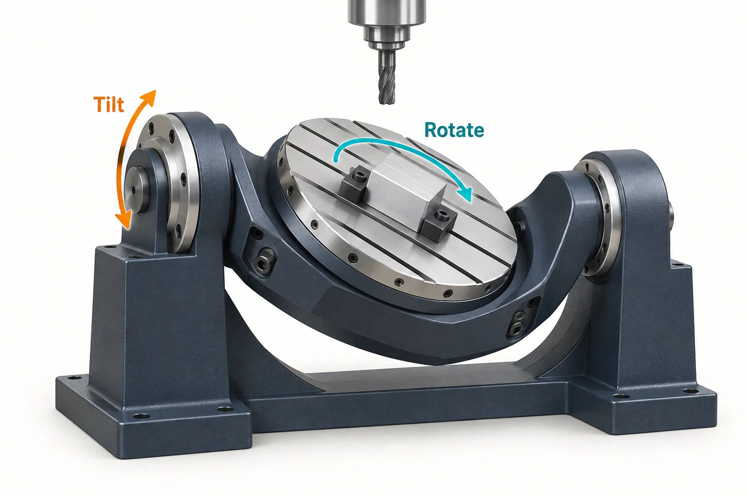
In five-axis CNC machining, two rotary directions let a machining system address combinations of tilt and rotation. That can help with holes on differently inclined faces, access beside tall features, or surfaces for which the tool direction needs to change along the path. It does not remove the need to check the cutter, holder and fixture against the actual geometry.
The rotations do not have to sit in the same place. A table-table machine rotates the workholding assembly in two directions. A head-head machine changes the spindle-head orientation, while a head-table design divides the rotary motions between the two. Hurco’s configuration guide illustrates why the same axis count can have different workspace and access implications.
Also distinguish the equipment from the cutting mode: 3+2 and simultaneous five-axis machining use the rotary axes differently. In 3+2 machining, the two rotary axes position the part or head, then remain at that orientation while the linear axes cut. In simultaneous five-axis machining, rotary and linear motion can be coordinated during cutting. All five axes need not move continuously in every segment.
HEIDENHAIN’s rotary-axis technical paper makes this positioning distinction explicit. A set of straight holes on several inclined faces may need several fixed orientations, without needing continuous five-axis tool motion. A surface that benefits from a continuously changing tool direction presents a different task.
Match the feature directions to a practical route
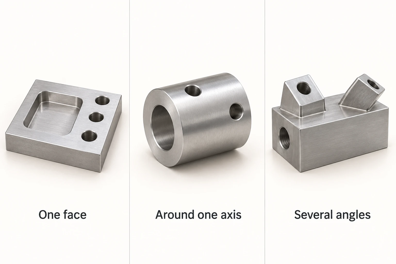
These illustrative parts show how the comparison changes with geometry. They are starting points for process planning, not fixed rules assigning every part shape to one machine type.
| Example part | Sensible starting route | What could change the choice? |
|---|---|---|
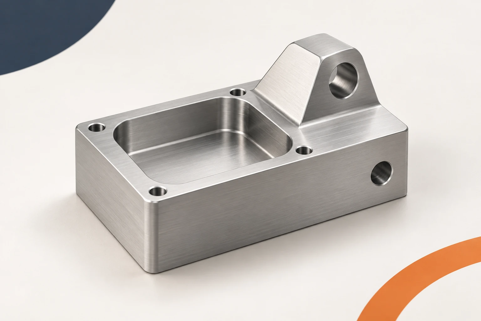
| Plate with a top pocket and vertical holes | 3-axis milling, if the tools can reach the pocket and holes in the chosen setup | A blocked feature, an additional side operation or a difficult tool-clearance condition |
| Collar with radial holes around its circumference | Indexed 4-axis milling to present the hole directions to the spindle | An axial end feature needs another approach; a continuous wrapped feature may require coordinated rotary cutting |
| Block with straight holes on several differently inclined faces | Compare separate 3-axis setups with 3+2 positioning | A changing tool direction along a surface may justify simultaneous 5-axis; a blocked clamping face still needs its own plan |
Notice that an angled hole is not automatically a five-axis requirement. A fixture can hold a part at a fixed angle on a three-axis mill. The tradeoff is the extra fixture or setup work, and how the required relationships between features are maintained. Conversely, a modest-looking part can justify rotary positioning if it otherwise needs repeated handling.
Axis configuration changes how the tool approaches the features; it does not replace the underlying cutting process.
Check the whole setup before favoring more axes
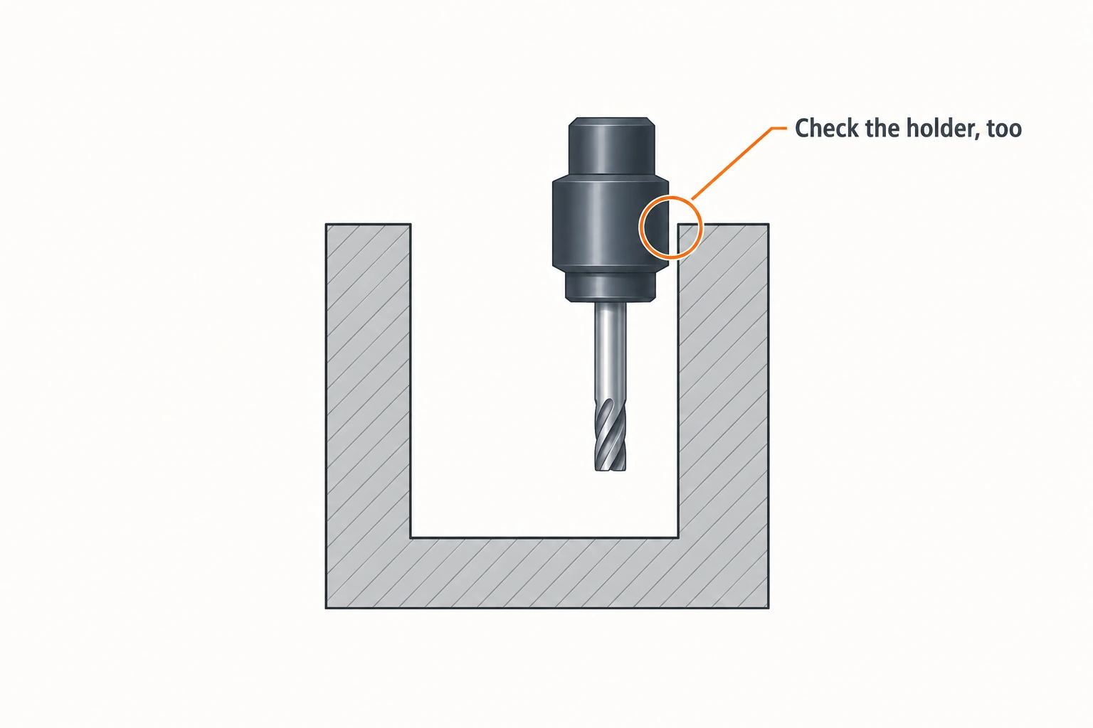
Tool reach is an assembly problem. A cutter tip may reach a surface while the wider holder collides with a wall. Tilting can sometimes create a useful approach with a shorter tool, but not every tilt improves clearance. Hurco notes that some table orientations can require longer tools to reach a feature. Sandvik Coromant’s profile-milling guidance likewise connects tool-extension choices to cavity geometry and vibration risk.
The fixture occupies real space. Adding a rotary table to a three-axis mill reduces the space available for the part and tooling. On a trunnion, check the swept space as the part rotates, not just the space it occupies while level. Faces covered by jaws or mounting stock do not become exposed merely because the machine has five axes.
Fewer setups remove some error opportunities, not every error source. Rotary positioning can reduce the need to re-establish a part’s location after reclamping. Finished accuracy still depends on rotary and linear-axis performance, calibration, thermal behavior, tool deflection and the workholding. An axis-count label is not a tolerance specification.
Compare the complete job. Additional rotary motion can save handling and support a better cutting approach, while also adding programming, verification or fixture work. A simple plate may gain little; repeated multi-face work may gain much more. The useful choice is the route that reaches the required features with manageable setup and cutting conditions.
Frequently asked questions
What is the main difference between 3-axis and 4-axis CNC machining?
A four-axis milling configuration adds one controlled rotary direction to X, Y and Z. It can present features around that axis without reclamping the part. Whether rotation can occur during cutting depends on the machine and control configuration.
Can a 3-axis CNC mill make curved surfaces or angled holes?
Yes. A suitable cutter can trace accessible curved surfaces using X, Y and Z. An angled hole can also be drilled when a fixture presents its axis to the spindle. The limits are access, tooling and setup—not the appearance of the CAD model alone.
Does a 5-axis CNC machine always cut with all five axes moving?
No. It may use three-axis cutting at a fixed orientation, indexed 3+2 machining, or supported simultaneous motion. The number of installed axes and the motion used for a particular cut are different things.
Can five-axis machining finish every face in one setup?
Not necessarily. Clamped or otherwise obstructed surfaces may need another setup. Tool reach, rotary travel and collision clearance also limit access, even when two rotary axes are available.


