On this page
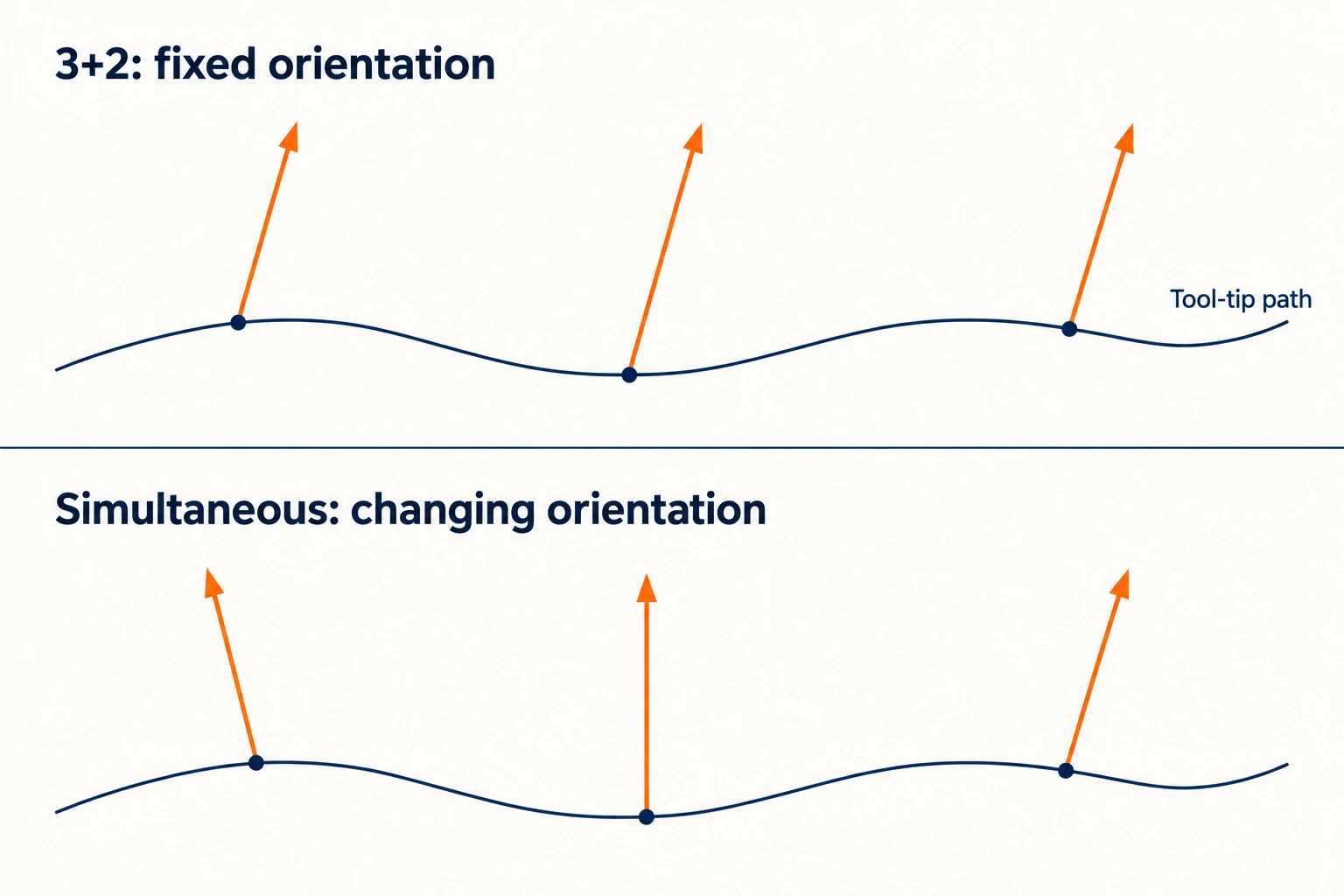
In 3+2 machining, two rotary axes establish an orientation and stay at that position while the linear axes cut. In simultaneous five-axis machining, rotary and linear motion can be coordinated to change the tool’s orientation relative to the workpiece during cutting. Both modes can be used on suitably equipped five-axis machines. The useful choice is often made operation by operation, rather than once for the entire part.
A set of inclined holes may need several fixed directions. A finishing pass may benefit from changing direction along a surface. The difference is what the tool needs to do during the cut. For the underlying machine configurations, the three-, four- and five-axis comparison explains which motions each arrangement adds.
Separate the tool’s path from its orientation
The tool-tip path describes where the cutter travels. Tool-axis orientation describes the direction in which its shaft points relative to the part. A curved path does not necessarily need a changing orientation: a ball-nose cutter can follow an accessible contoured surface while its shaft direction stays fixed.
| Question | 3+2 positional machining | Simultaneous five-axis machining |
|---|---|---|
| What happens during a cutting pass? | The rotary positions stay fixed; the linear axes generate the path. | The program can coordinate linear and rotary motion to vary the relative tool direction. |
| How does the next direction become available? | Retract, reposition, then begin another fixed-orientation cut. | Change orientation within a cutting path where the strategy and clearance permit it. |
| What is the main reason to choose it? | One fixed approach works for each selected operation. | Changing approach during a pass provides a useful access or cutting-contact benefit. |
This is a distinction between machining modes, not a rule that simple-looking parts use one and complex-looking parts use the other. Autodesk’s machining-type documentation places 3+2 tool orientation alongside three-axis toolpaths, including three-dimensional finishing strategies.
What a 3+2 operation actually does
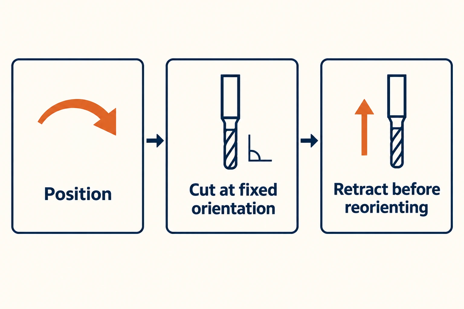
Imagine drilling holes normal to an inclined mounting pad. The machine first presents that pad to the spindle. Once positioned, the rotary axes remain stationary while the drill enters and leaves the holes. The machine can then retract and reorient for another pad without releasing the part from its fixture.
A typical positional sequence is:
- Move the tool clear of the workpiece and fixture for the planned reorientation.
- Position the rotary axes and establish the corresponding machining coordinates.
- Cut the selected features with the rotary positions held.
- Retract before moving to the next orientation.
“Held” does not specify a universal mechanical brake or clamping arrangement; that depends on the machine. Likewise, a clear starting and ending position does not prove that the intervening rotary movement clears the fixture.
The same fixed orientation can support pocketing, contouring or three-dimensional surface milling, not just drilling a flat face. HEIDENHAIN’s TNC milling-control guide explains coordinate transformations for machining in a tilted working plane. For the cutting operations themselves, see how CNC milling works.
When changing orientation earns its place
Simultaneous five-axis machining adds control over the tool direction along the cutting path. Depending on the geometry, that can help keep the holder clear of nearby surfaces, maintain a useful cutting contact, or continue a finishing pass through a region that would otherwise need separate orientations.
The machine may achieve this by tilting the workpiece, moving the spindle head, or combining both. What matters is the resulting tool-to-part relationship. The tool does not have to stay perpendicular to the surface: the chosen tilt follows the cutting strategy and clearance requirements.
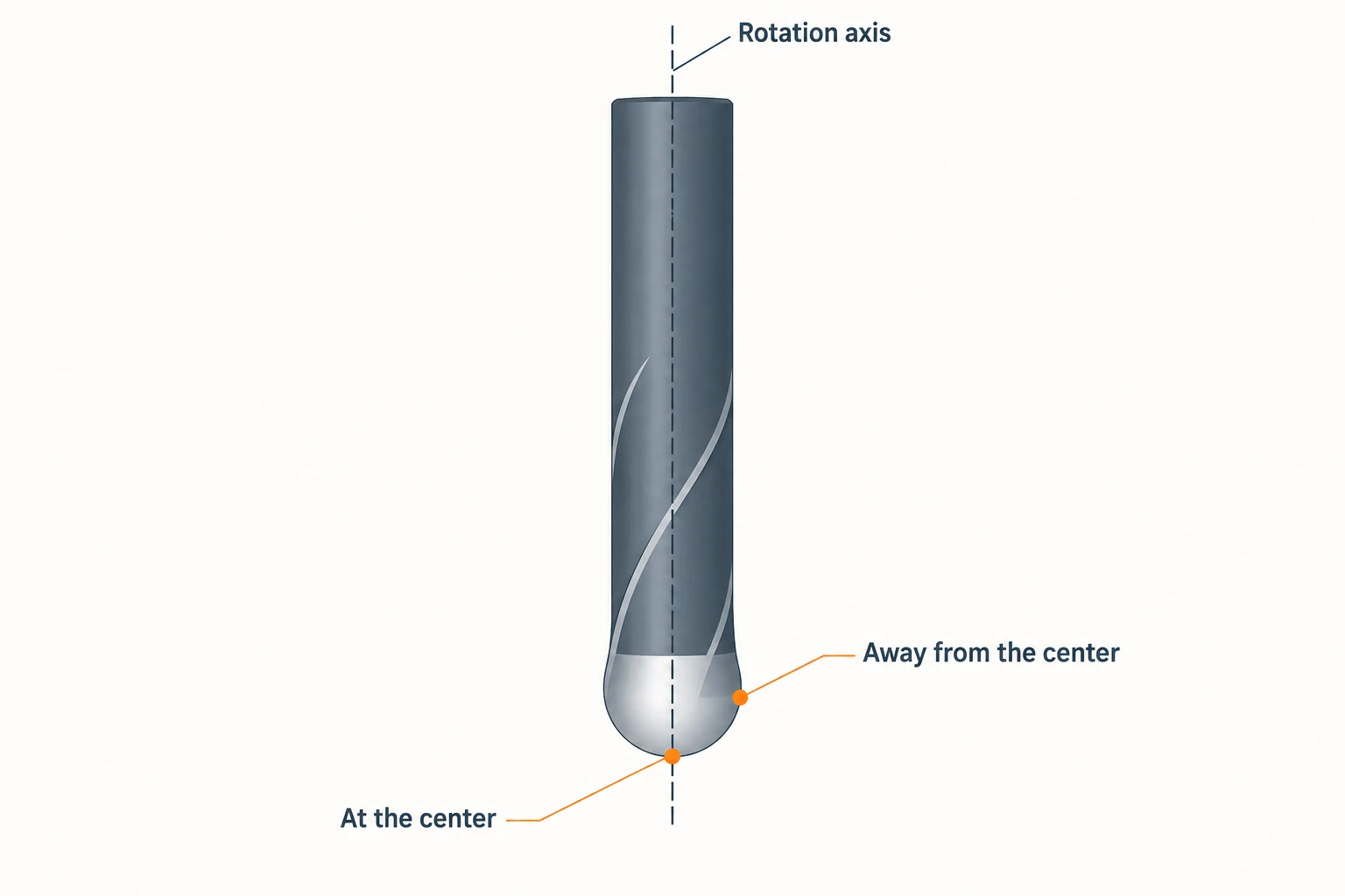
A ball-nose cutter provides a concrete example. Its rotational cutting speed approaches zero at the end center. Moving contact away from that center gives the engaged edge a larger radius of rotation. Sandvik Coromant’s profile-milling guidance explains why tilting can improve that contact condition. A fixed tilt may suffice for one region; changing surface slopes may make a varying tilt useful. There is no single useful angle for every tool and part.
That benefit is conditional. A poor orientation strategy can create holder interference or difficult rotary motion. Surface finish also depends on cutter geometry, spacing between passes, feed, runout and vibration. Neither a smooth surface nor a good finish is exclusive to simultaneous machining, and neither follows automatically from selecting it.
One part can use both strategies
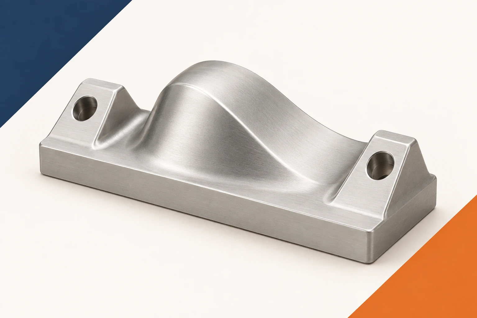
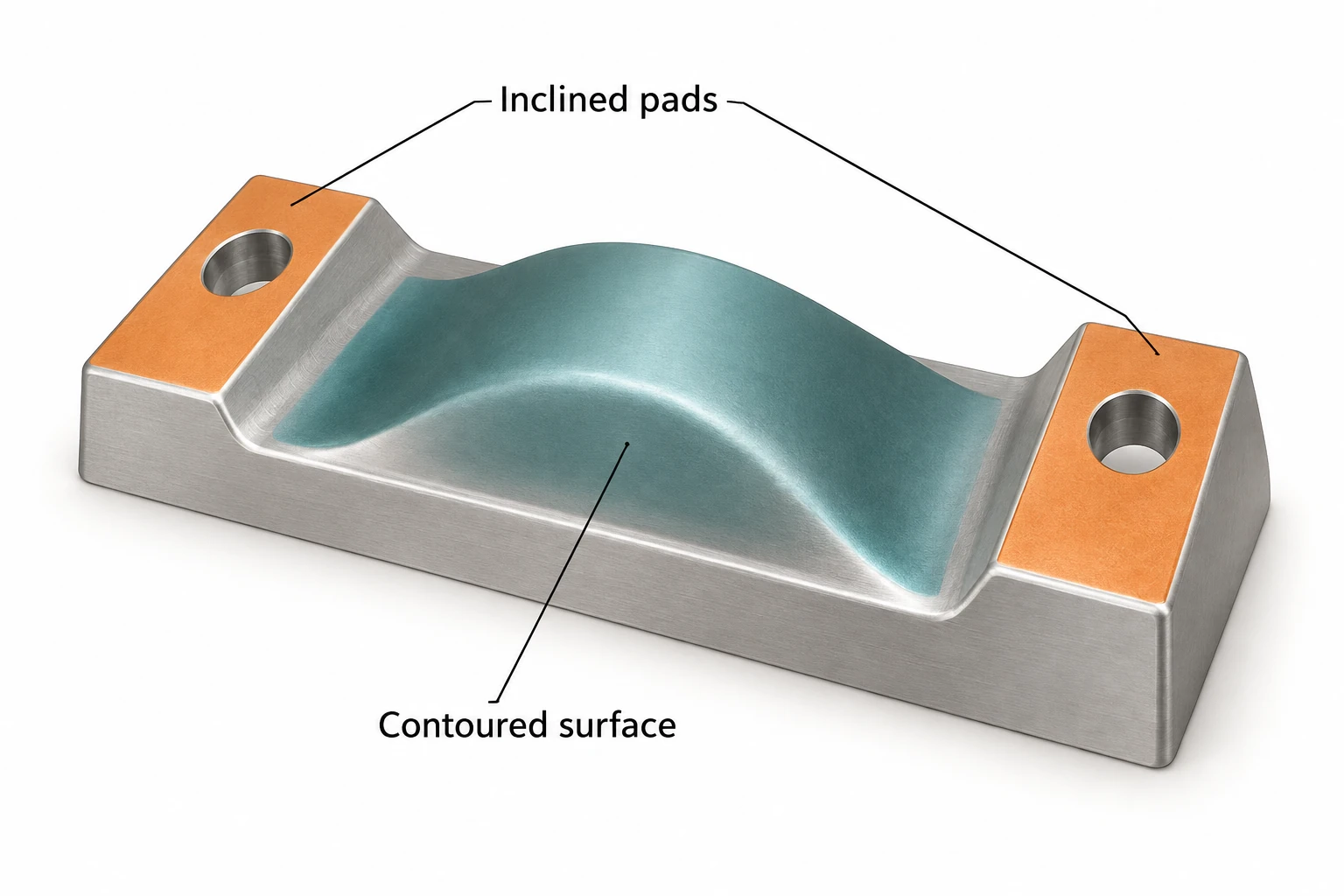
Consider an illustrative tooling insert with inclined mounting pads and a smoothly changing central form. For five-axis CNC machining, treat each operation as a separate question about access and contact, while preserving a workable holding arrangement.
| Operation on the insert | Starting approach | Reason to reconsider |
|---|---|---|
| Remove accessible stock above the base | Three-axis roughing from a fixed orientation | Remaining stock becomes inaccessible or requires excessive tool reach. |
| Drill the inclined pads | 3+2 positioning for each pad’s hole direction | The holder or fixture blocks the approach, even after positioning. |
| Finish the central form | Test a fixed-orientation finishing path first; consider simultaneous motion where changing direction helps. | One fixed direction gives poor contact or clearance; dividing the form into indexed regions adds undesirable transitions. |
| Finish a surface covered by the fixture | Plan another holding arrangement or setup. | Neither cutting mode exposes material that remains physically clamped or obstructed. |
The central form is not automatically a simultaneous-five-axis feature because it is curved. If one orientation provides suitable access and contact across it, a fixed-orientation path may be sufficient. If several indexed regions are used, plan how their finishing passes meet; visible boundaries can result from mismatched cutting conditions or positioning, but they are not an unavoidable property of 3+2.
This mixed route keeps ordinary cuts straightforward and reserves changing orientation for the operations that gain from it. It also separates a change of cutting mode from a physical reclamping of the part.
Make the program fit the machine
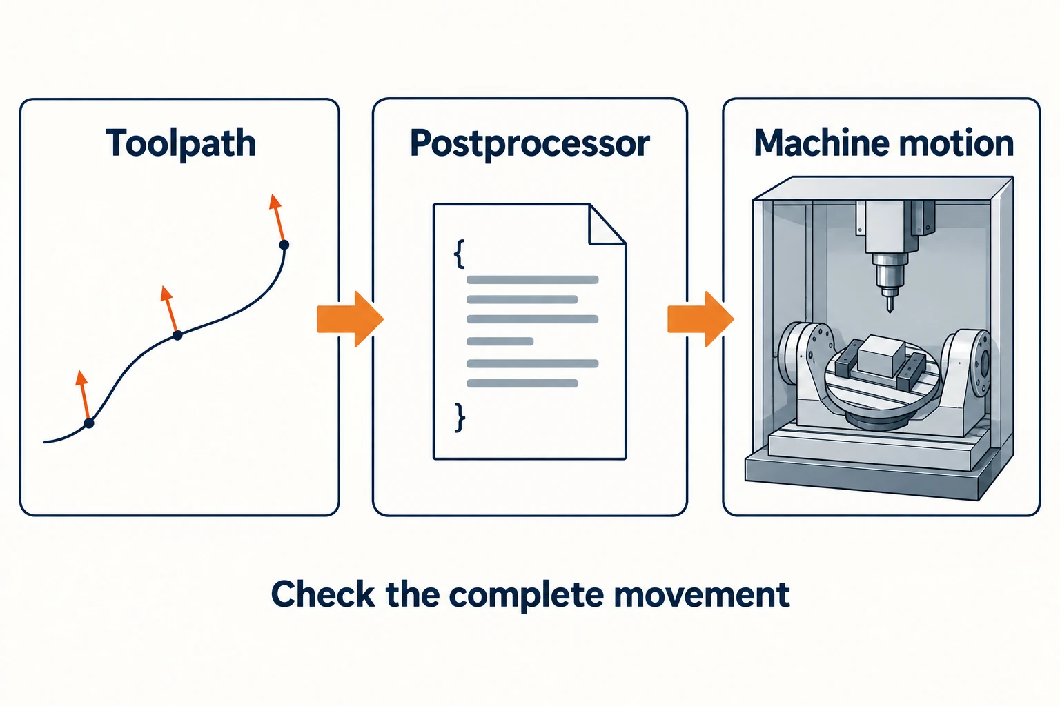
A CAM toolpath is only part of the result. The postprocessor translates it into instructions for a particular machine and control. The machine’s rotary layout, direction conventions, travel limits, tool lengths and work offsets must agree with that translation.
Coordinate functions also have different jobs. A tilted working plane establishes coordinates for machining at a selected orientation. Tool-center-point control accounts for changing rotary positions and tool geometry when producing the commanded tool motion. Their names and implementation vary by control; the presence of a positioning function does not establish simultaneous-cutting capability.
For example, Haas documents Dynamic Work Offset for 3+1 and 3+2 positioning separately from Tool Center Point Control for simultaneous contouring. These are examples of a specific control’s functions, not interchangeable commands for other machines. Coordinate handling must match the selected postprocessor, machine configuration and control functions.
Before machining, verify more than the cutter touching the intended surface:
- The complete tool assembly: include the holder and tool length actually used.
- The complete movement: include approaches, retracts, indexing and any required rotary repositioning, as well as cutting passes.
- The actual setup: include remaining stock, fixture geometry and machine travel limits.
Autodesk’s machine-simulation documentation distinguishes checking toolpaths with a machine model from simulation without one. A simulation can only check the geometry and machine behavior it represents; it does not replace checking the setup or inspecting the finished part.
Compare the complete operation
Compare the two routes against the same part requirements. Include programming and verification, tools and fixtures, cutting time, indexing and retract moves, and any later finishing or extra setup work.
3+2 can be efficient when a few fixed directions complete the work. Simultaneous motion may remove repeated transitions or improve contact along a surface, but changes in tool direction also require the rotary axes to accelerate and decelerate. Autodesk’s tool-axis smoothing guide explains how abrupt orientation changes can disrupt smooth movement. A more continuous-looking path is not necessarily the shorter production route.
The useful test is specific: identify the operation that needs changing orientation, name the benefit, and check that the complete machine motion can deliver it. Use that result to choose the mode for each operation.
Frequently asked questions
Is 3+2 machining a form of five-axis machining?
Yes. It is often called positional or indexed five-axis machining. Two rotary axes set an orientation, while the linear axes perform the cut with those rotary positions held. It differs from simultaneous five-axis cutting.
Does simultaneous five-axis machining mean all five axes move in every block?
No. The program coordinates the axes needed for each segment. A simultaneous five-axis program can contain segments with unchanged rotary positions, as well as segments that change orientation during cutting.
Can 3+2 machining produce a smooth curved surface?
Yes, if a suitable tool can reach and finish the surface at the selected fixed orientation. Curvature alone does not require simultaneous motion. Tool contact, clearance and the way adjacent passes meet determine whether changing orientation would help.
Can one program combine 3+2 and simultaneous operations?
Yes, on a machine and control that support the required modes, with a correctly configured postprocessor. Transitions between modes need the appropriate coordinate and compensation handling, plus clearance checks for the linking movements.


