On this page
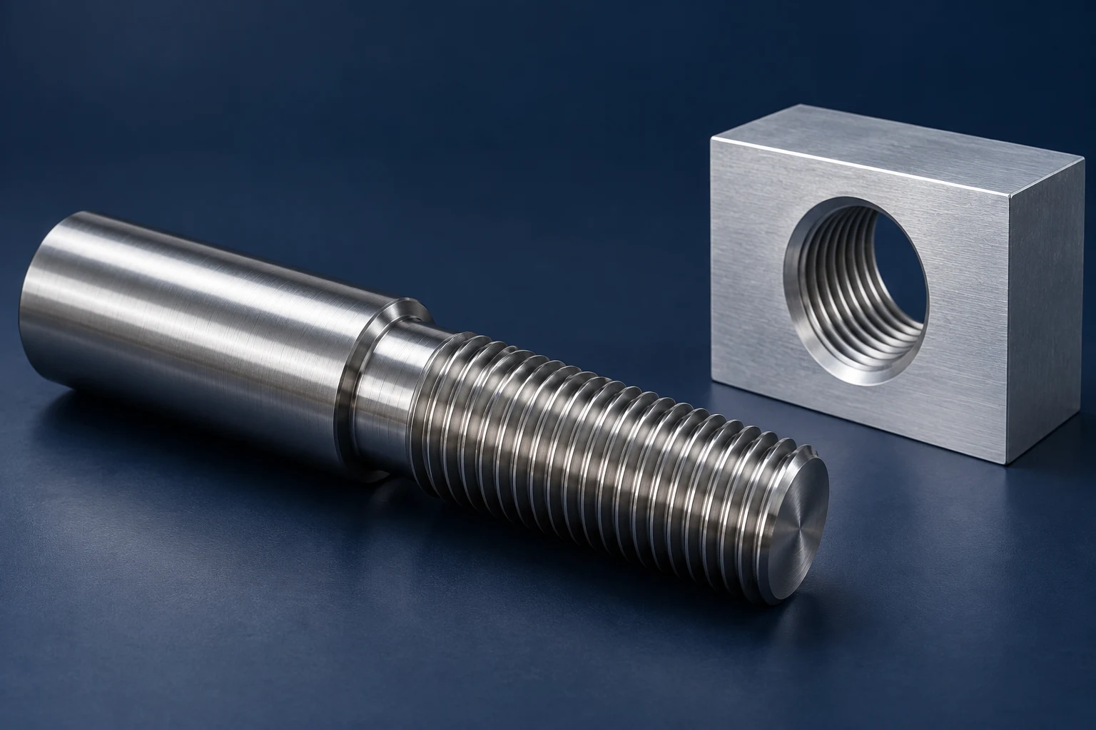
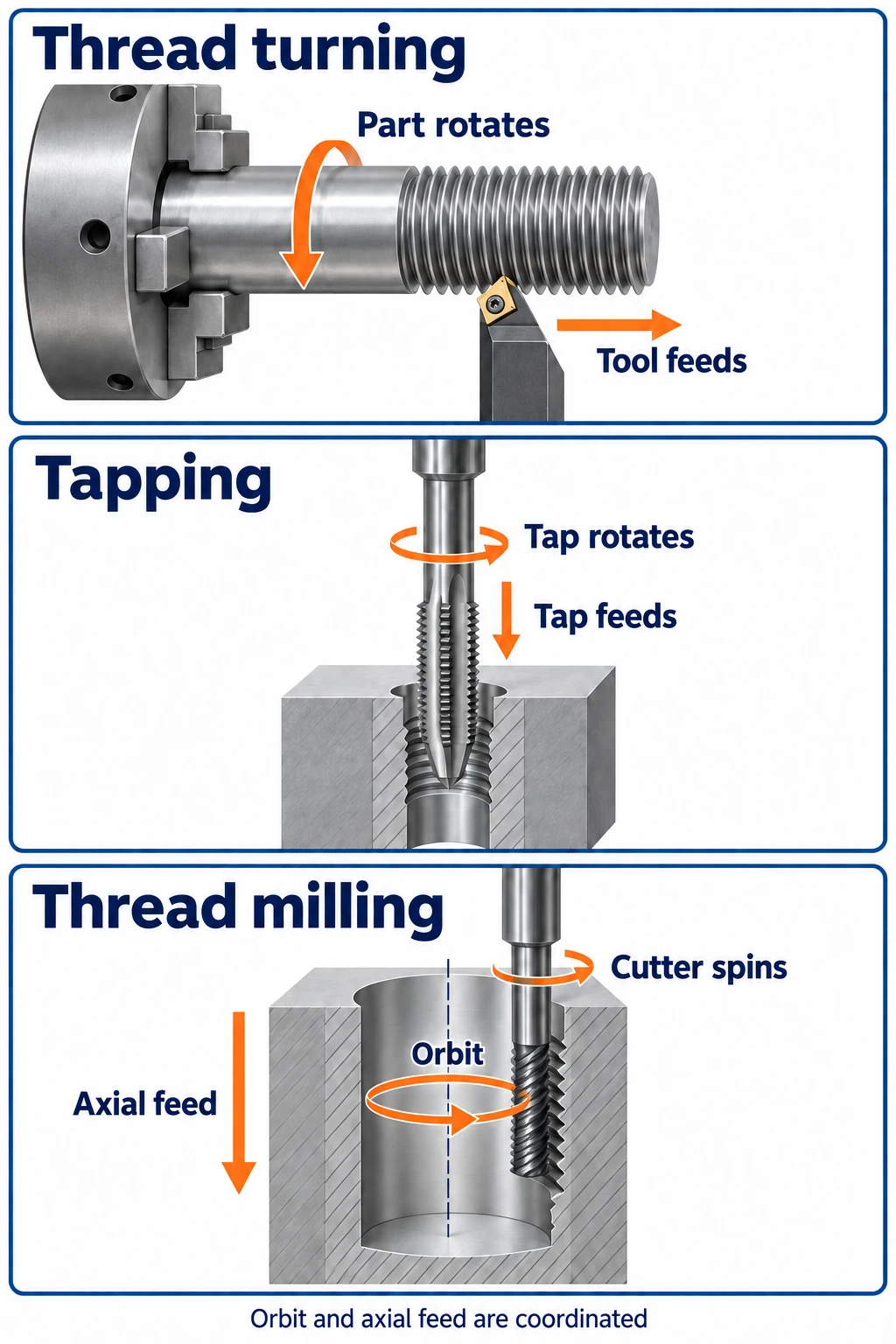
Thread turning uses a cutting tool synchronized with a rotating workpiece. Tapping uses a tap to cut or form an internal thread. Thread milling uses a rotating cutter that follows a helical path, and suitable tools can produce either internal or external threads.
The best starting point is the thread’s location and the way the part is held. An external thread on a shaft often suits turning. For a threaded hole in a block, the more useful comparison is usually tapping versus thread milling. Tool access, material, thread size and production requirements then narrow the choice. For a threaded fastener, the custom machine screws page also covers the head, drive and shank geometry.
How the three methods make a thread
| Method | Thread location | What moves in a typical setup | What creates the thread |
|---|---|---|---|
| Thread turning | External or internal | The workpiece rotates; the tool advances along its axis. | A shaped cutting edge follows the same helix over successive cuts. |
| Tapping | Internal | The tap and hole rotate relative to each other while advancing axially. | The tap’s geometry cuts or forms the thread as it enters the hole. |
| Thread milling | External or internal, with suitable tooling | The cutter spins and travels around the thread axis while moving axially. | The cutter profile and programmed helical path generate the thread. |
Thread turning follows the rotating part
In CNC turning, a threading insert cuts the outside of a shaft, or a threading bar reaches inside a bore. Successive passes deepen the thread. The tool’s axial travel is synchronized with the workpiece rotation so that each pass follows the same groove.
That travel per revolution is the lead. For a single-start thread, lead equals pitch—the axial distance between adjacent thread crests. A multi-start thread has more than one helix, so its lead is greater than its pitch. This distinction matters when describing the motion, even though ordinary single-start threads are the focus here.
Internal turning needs enough bore space for the bar and cutting edge. A long, slender bar also makes vibration and chip removal harder to manage. These are central concerns in internal thread turning.
Tapping brings the thread form into the hole
A tap is selected for the required thread size, pitch and form. Its rotation relative to the hole and its axial movement must stay coordinated. The tap can rotate in a stationary block, or a lathe arrangement can provide relative rotation through the workpiece; tapping is not limited to milling machines.
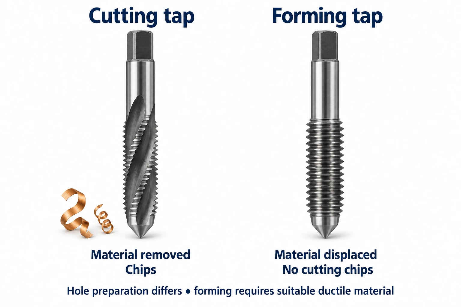
Cutting taps remove material and produce chips. Forming taps, also called roll taps, displace sufficiently ductile material to create the thread without cutting chips. Form tapping needs its own hole preparation and lubrication: the starting hole size for a cutting tap cannot simply be carried over. The choice of tap type depends on both the material and the hole.
Thread milling adds an orbit around the thread axis
A thread mill spins about its own axis while the machine carries it along a helix. For an internal thread, the cutter is smaller than the hole and moves around its wall. For an external thread, it travels around the outside of the feature.
On a machining center used for CNC milling, thread milling involves coordinated movement in the two axes describing the circle and the third axis along the hole. For a single-start thread, one complete orbit around the thread axis advances one pitch; one revolution of the cutter itself does not. The distinction is visible in thread-milling toolpaths.
What changes the choice?
Start with the setup you already need
If a shaft is already being turned, adding a thread in the same setup can be a straightforward route. A large, irregular housing held on a machining center presents a different problem: tapping or thread milling can reach its holes without rotating the entire housing around each hole’s axis.
The machine label alone is not decisive. A turning center may support tapping and, with the necessary driven tooling and coordinated axes, thread milling. Check the actual configuration and access to the feature. For each method, the tool and holder must clear the surrounding geometry throughout the operation.
Blind holes need room beyond the full threads
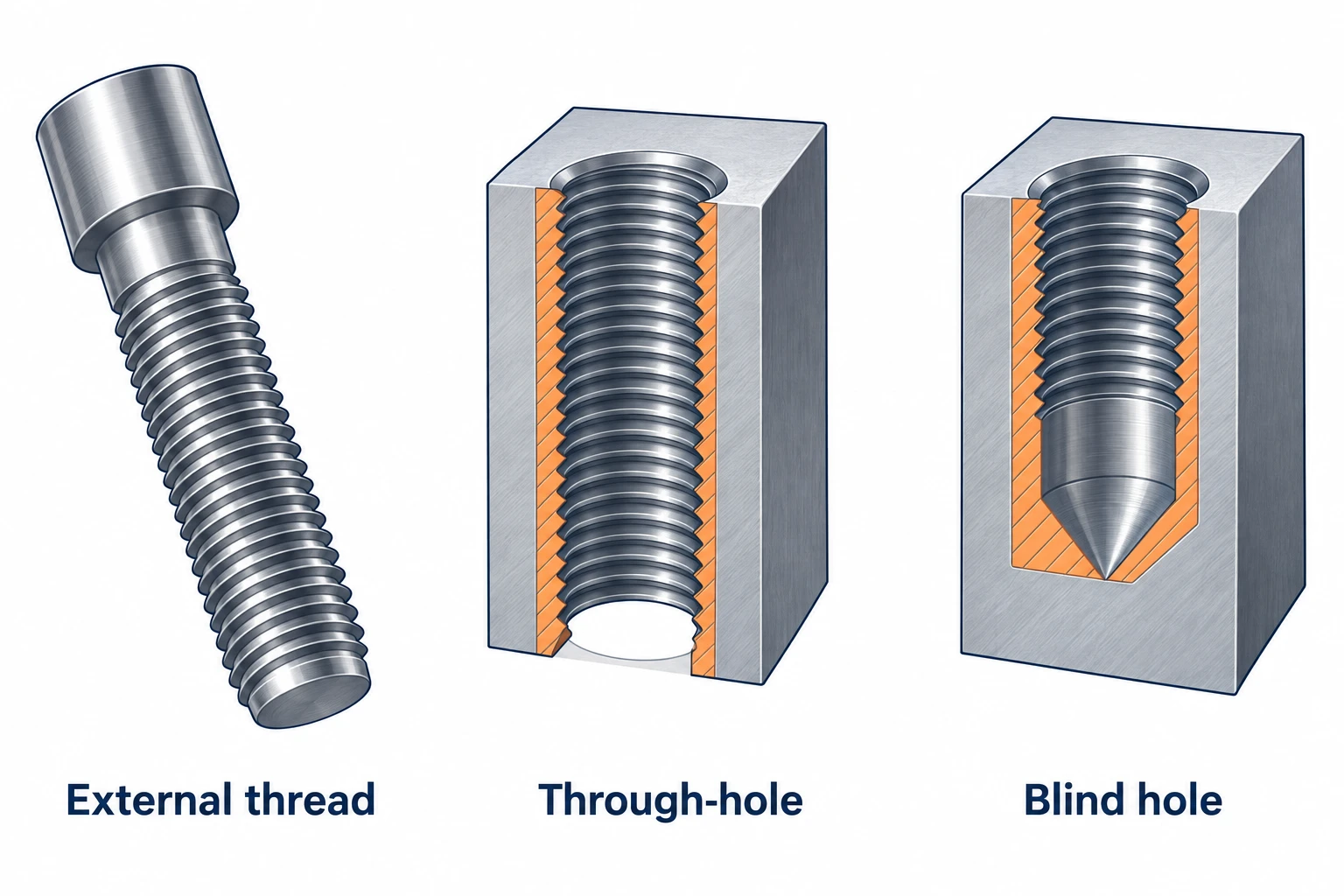
A blind hole ends inside the part. Its drilled depth and its length of complete thread are different dimensions. The tapered cutting or forming lead on a tap reaches beyond the last full thread it produces, while the drilled hole may end in a cone. A bottoming tap shortens the lead, but it still needs room.
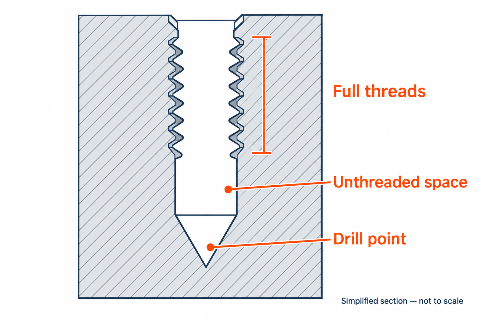
A suitable thread mill can cut closer to the bottom, but its cutting profile, neck and entry path still need clearance. Choose the tool against the required full thread length and available hole geometry. Extending the drilled hole is only an option if the part has enough material below it. The machining design guide covers the wider design considerations.
Size adjustment and tool reuse favor different tools
Thread milling allows the programmed cutting path to be adjusted to bring thread size into tolerance. This can help with fit control and compensation for wear; EMUGE describes this use of tool-offset adjustment. Turning also provides size adjustment through tool position. With tapping, size control relies more directly on selecting the appropriate tap geometry and tolerance, then controlling hole preparation and the process.
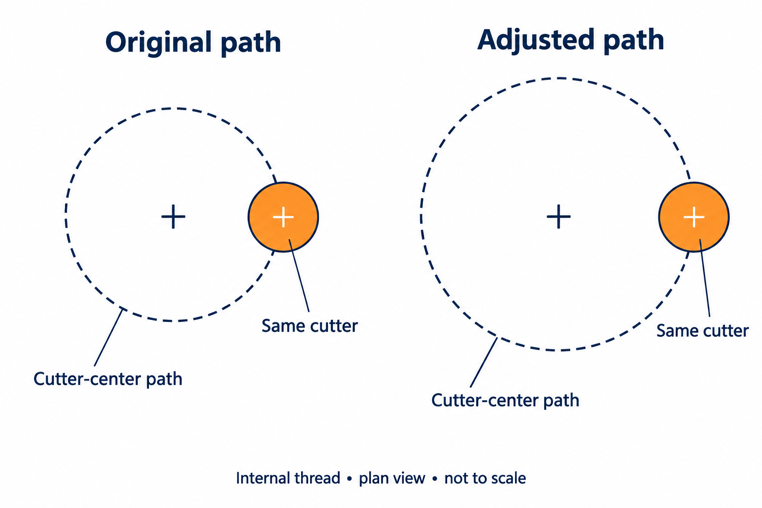
Tool reuse has limits. A multi-row thread mill may cut several diameters at the same pitch, within its usable range. Certain single-row tools cover a range of pitches, but their profile angle, cutting geometry and clearance must still suit the thread. Single-row and multi-row cutters offer different kinds of flexibility. Changing the program cannot turn an unsuitable cutter into the right one.
Compare the complete operation, including failures
Tapping is often productive for repeated, standard internal threads when the tap, material and hole geometry work well together. Thread milling adds an orbital toolpath, and some applications need more than one cutting pass. Its extra control can nevertheless be useful when a difficult hole or a nearly finished part makes process reliability especially valuable.
Cutting taps and forming taps also have different chip considerations: chip evacuation matters for the former, while material flow, hole size and lubrication matter for the latter. Thread milling creates chips too, and its cutter can still break or deflect. Compare actual cycle time, tool life, inspection and recovery or scrap costs for the intended setup rather than assigning one method a universal speed or accuracy advantage.
Three parts, three different starting points
These illustrative cases show how part geometry changes the comparison.
| Part and feature | Starting point | What could change the choice? |
|---|---|---|
| A steel adjustment spindle with an external thread beside a shoulder | Thread turning, using the setup that machines the shaft. | The thread runout and tool exit must fit the shoulder geometry. Restricted access may require a different tool or route. |
| An aluminum mounting block with repeated standard threaded through-holes | Tapping, with a tool matched to the alloy and hole. | Mixed thread sizes, unstable chip control or a need for size adjustment may justify thread milling. Form tapping depends on material suitability and the specified requirements. |
| A nearly finished housing with a blind thread close to the hole bottom | Evaluate thread milling for access to the required full thread length. | The cutter and holder must fit, and the machine must support the path. A suitable short-lead tap may still be a practical solution. |
Choose for the feature, then verify the thread
Start with an external or internal thread, the existing setup and the available tool clearance. Then compare the practical tradeoffs: tapping’s direct approach to repeated holes, turning’s fit with rotating parts, and milling’s control over a helical path. All three can produce useful threads when the application and tooling match.
The method is not the acceptance requirement. The finished thread still has to meet its specified form, size, fit and usable length. If you are discussing a part with a supplier, those details make the choice meaningful.
Frequently asked questions
What is the difference between thread turning, tapping and thread milling?
Thread turning cuts a thread by synchronizing a tool’s axial feed with the workpiece rotation. Tapping cuts or forms an internal thread with a tap. Thread milling uses a spinning cutter moving along a helical path. Turning and milling can make internal or external threads when the tooling and access suit the feature.
When should I choose thread milling instead of tapping?
Consider thread milling when you need to adjust thread size through the programmed path, use one compatible cutter across several thread diameters, or reach closer to the bottom of a blind hole. The cutter’s profile, reach and clearance must suit the thread, and the machine must support the helical path. Tapping can remain a productive choice for repeated standard holes.
Can a blind hole have full threads down to its drilled depth?
Full threads do not extend to the tip of a conventional drill point. The tap’s lead also needs space beyond the last complete thread, even with a bottoming tap. A suitable thread mill may reach closer to the hole bottom, but it still needs clearance. Specify the required full thread length separately from the drilled depth.
Does tapping always produce chips?
No. Cutting taps remove material and produce chips; forming taps displace sufficiently ductile material without cutting chips. Form tapping requires a suitable starting hole and lubrication. A hole prepared for a cutting tap cannot automatically be used with a forming tap of the same nominal thread size.


