On this page
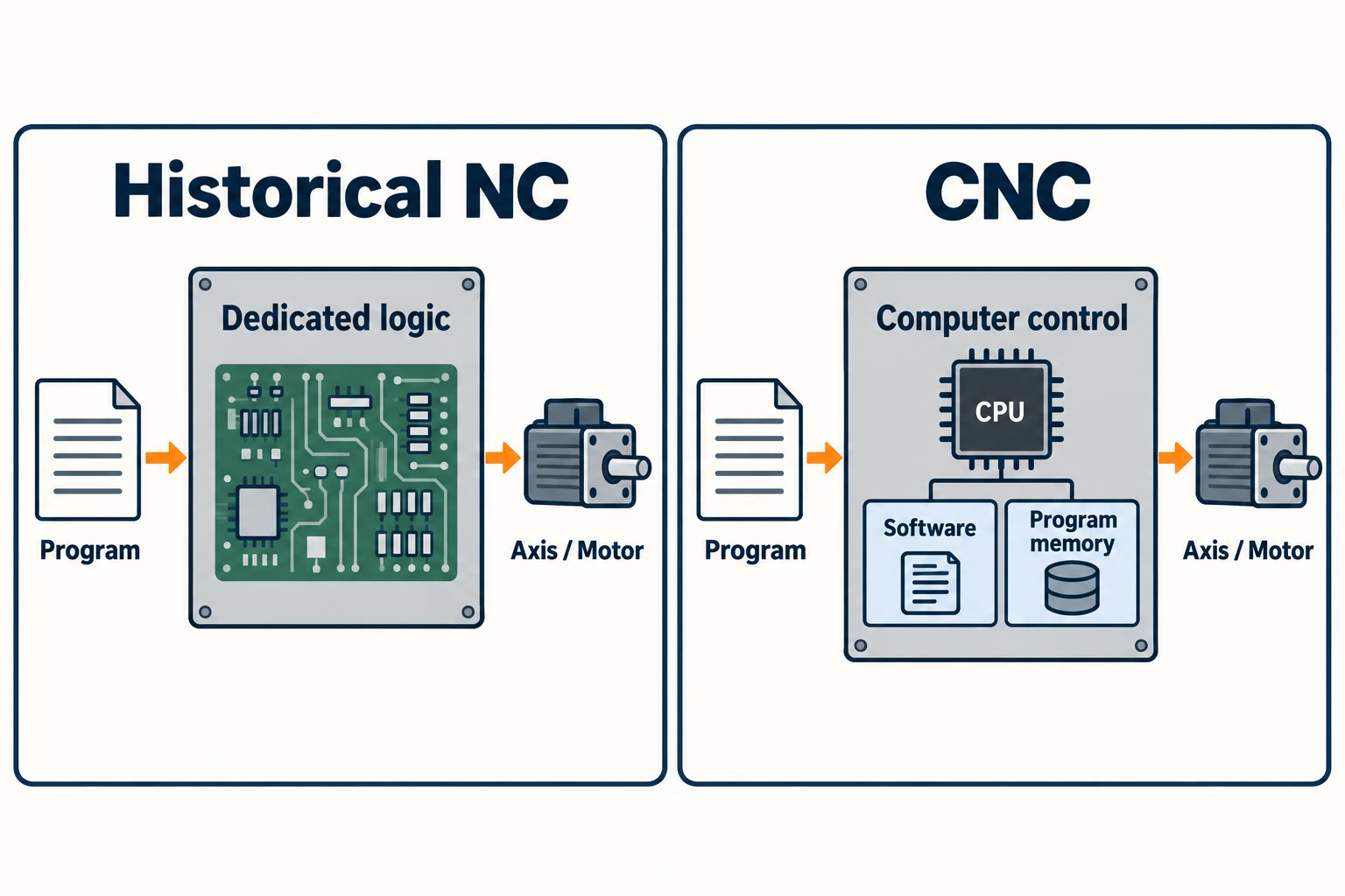
NC means numerical control: a machine follows coded numerical instructions. CNC means computer numerical control, a form of NC that uses a computer to control machine functions. In a historical NC-versus-CNC comparison, “NC” usually means an earlier control whose functions were implemented in dedicated electronic hardware. CNC moved those functions into a computer-based system with software and program memory.
The important change was how the control handled instructions and how readily a machining program could be stored, revised and reused. It was not the invention of automatic motion itself. Early NC machines already followed programs, and some already used feedback and produced contoured shapes.
What the computer changed inside the control
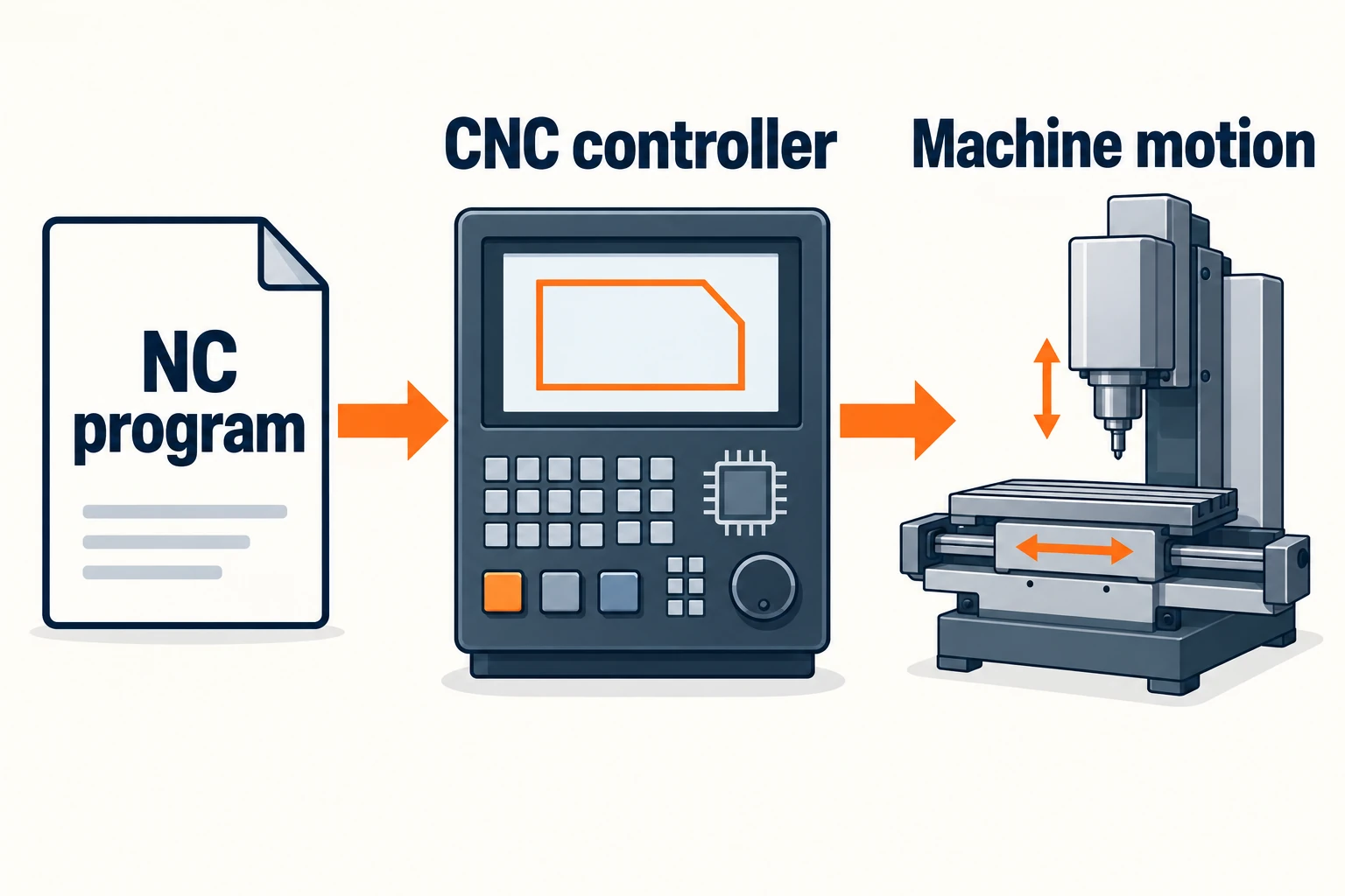
Separate the part program from the control logic. The part program describes a particular job: positions, movements and machining commands. Control logic interprets that information and carries out the machine’s control functions. The guide to how a CNC system controls machine motion follows those instructions through the controller, drives and feedback.
A historical hardwired NC used dedicated circuits for those functions. “Hardwired” does not mean that a different hole pattern required rewiring the machine. A different part program could still tell the control to make different moves within its capabilities. What was less flexible was the implementation of the control itself and the handling of programs at the machine.
A CNC implements numerical-control functions using a computer. Software, processing hardware and memory make it possible to handle instructions as editable data. FANUC’s account of its 200A control, developed in 1972, gives a concrete example: the control allowed machining programs stored in memory to be edited. That is a more useful distinction than a blanket claim that NC was unprogrammable.
From punched tape to programs in memory
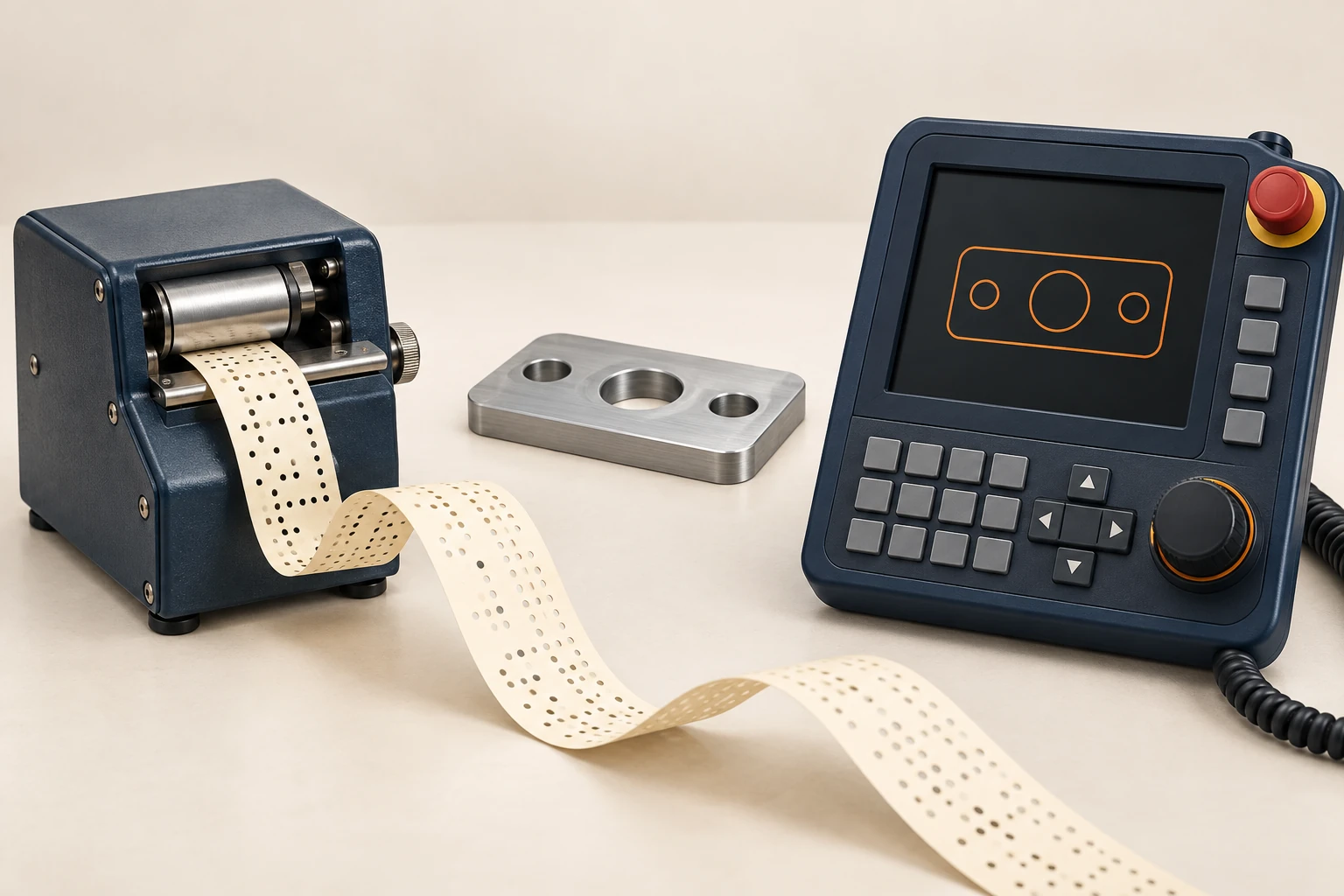
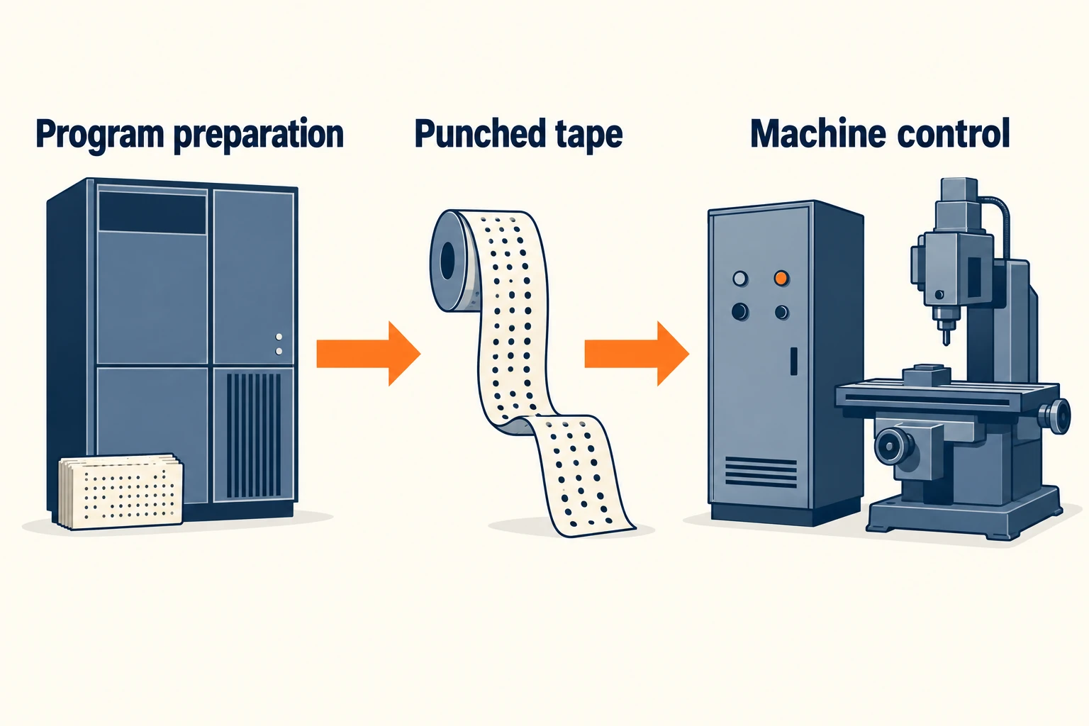
Punched tape gave numerical instructions a physical form that a reader could detect. It carried the program; it did not supply the force to move the machine. In MIT’s 1952 description, an electronic director decoded the tape and worked with servomechanisms to move a milling machine. The account also described information returning about motion progress.
Computers entered the workflow at more than one point. In MIT’s 1959 demonstration of Automatically Programmed Tools (APT), an external computer calculated instructions and produced a tape for the machine. Computer-assisted program preparation was therefore possible without the machine’s control itself being a CNC.
| Documented example | What it shows |
|---|---|
| MIT, 1952 | A tape-directed milling machine with electronic control and servomechanisms was already operating. |
| MIT APT demonstration, 1959 | A computer could prepare machining instructions offline and output a tape for a separate machine control. |
| FANUC 250, 1964 | A computer-based control was developed for a specialized rotary-engine grinding application. |
| FANUC 200A, 1972 | A multipurpose CNC supported editing machining programs held in memory. |
These are specific milestones, not a single worldwide changeover date. FANUC describes the 1964 system as a special-purpose development, rather than a control intended for general machine tools. The later memory-and-editing example illustrates a different stage of the transition.
One hole moves: how the program revision differs
Consider a hypothetical plate with three equal holes. Revision B moves the middle hole to a new location; the plate outline, hole diameters and other two positions stay the same. The next blank must be machined to the new design.
Both historical NC and CNC can express a changed position, provided the move is within the machine’s capabilities. The difference is the route from the design change to the instructions available at the control.
| Task | Historical tape-fed NC workflow | CNC workflow |
|---|---|---|
| Revise the instructions | Change the program information used to prepare the tape, then produce the corrected tape or section. | Edit the stored part program, or revise its source and generate a replacement program file. |
| Make the revision available | Identify and load the correct revised tape. | Transfer or save the revised program and select the intended version for execution. |
| Check the result | Verify that the changed instructions, setup and resulting hole location agree. | Verify the same relationship; an editable file does not establish that the correct revision is running. |
The older route was not necessarily all hand calculation. In the 1959 APT demonstration, changing a few input statements changed the computed geometry before a new tape was produced. CNC brought program handling into the control as well: the Haas Device Manager manual documents creating, copying, editing and selecting stored programs.
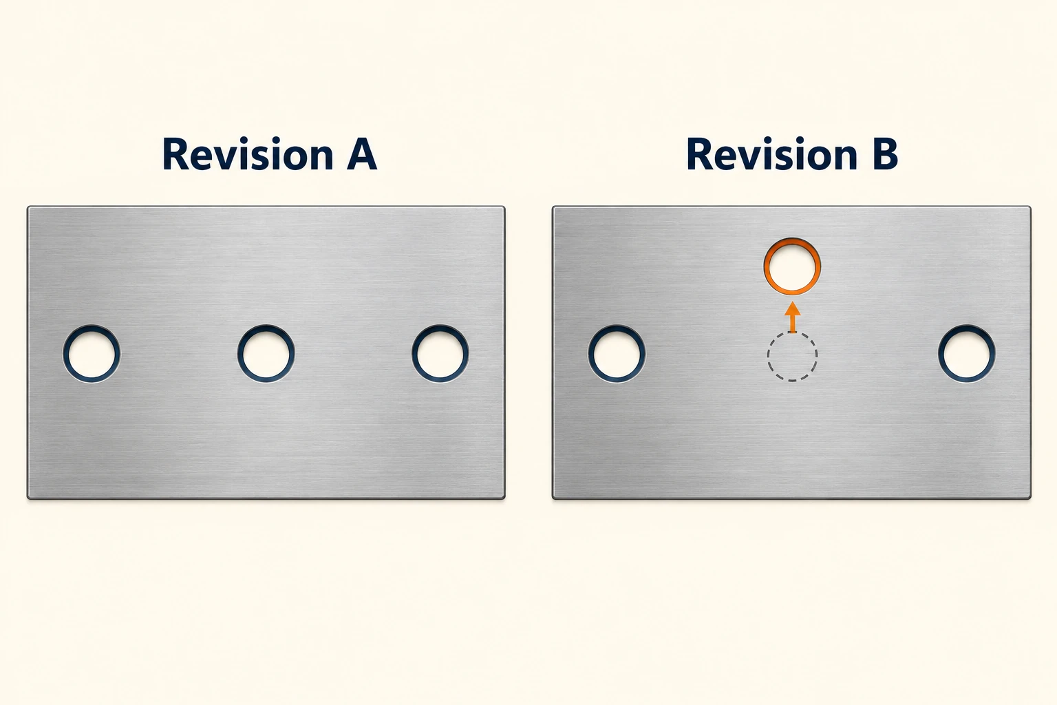
For the revised plate, shifting the entire work coordinate system would also shift the two holes that should remain unchanged. The affected feature’s program data must change instead. Easier editing reduces the friction of making that change; it does not decide which geometry the designer intended.
Why “NC program” still appears on CNC systems
NC remains the broader term. A document headed “NC program” does not identify an old hardwired machine. For example, HEIDENHAIN’s current programming-station description uses “NC programs” for programs created and tested for its computer-based controls.
File naming is another separate layer. Haas documents an example program exported with a .nc filename, while HEIDENHAIN explains that its conversational and DIN/ISO programs use different extensions. A file extension alone does not tell you which instructions a particular control accepts.
Likewise, a tape reader describes an input method. A screen describes an interface. Neither observation alone establishes how the control functions are implemented. The useful question is whether a computer performs numerical-control functions, rather than whether a computer helped prepare the program somewhere else.
Reading the terms this way avoids a common mistake: treating NC, CNC, program format and transfer method as four competing machine types. They describe different parts of the same workflow.
What the labels do not prove
Feedback is a separate distinction. A closed position loop uses measured axis position to correct the motion; an open position loop does not. MIT’s early system already exchanged motion information with its servomechanisms. “NC is open loop, CNC is closed loop” therefore fails as a general definition.
Curved geometry is not exclusive to CNC. The 1959 APT demonstration discussed contoured parts and approximating a curved path with short straight segments. A control’s available path functions and the way a curve is represented matter more than the historical label.
The cutting process still depends on the machine and setup. Changing control architecture does not by itself change a spindle’s power, the reach of a cutter or the restraint provided by a fixture. Our manual-versus-CNC milling comparison explains how programmed motion fits into the wider machining process.
The lasting advance was flexibility in implementing control functions and managing machining instructions. To understand a particular system, distinguish its control architecture, program workflow and actual motion capabilities. Those three descriptions explain much more than the presence or absence of the letter C.
Frequently asked questions
Is CNC a type of NC?
Yes. Numerical control is the broader concept; CNC implements it using a computer to control machine functions. In historical comparisons, “NC” is often used more narrowly for earlier hardwired controls.
Could an NC machine’s program be changed?
Yes. A tape-fed NC could receive revised instructions through a corrected or replacement tape. Hardwired control logic did not make every part program permanent. CNC added more flexible storage and editing at the control.
Does an NC program file require an old NC machine?
No. Modern CNC systems also use the term NC program. Compatibility depends on the program’s instructions and the target control, not just the name or file extension.
Did CNC introduce all automatic machining?
No. Earlier NC machines already executed programmed motion. CNC changed how control functions and programs were implemented and managed; it was an evolution within numerical control.


