On this page
A vertical machining center’s X, Y and Z travels describe motion, not a guaranteed maximum part size. The usable setup also depends on the table, fixture, tool assembly, approach path and clearance inside the machine. A blank can fit on the table while its programmed toolpath exceeds an axis limit; a short part can become too tall once the fixture and tool are included.
Read VMC technical specifications as separate constraints on a particular operation. Start with space, then check load, cutting performance, tool capacity and accuracy.
Travel and table size answer different questions
The Haas VF-2 specification page makes the distinction visible. For its listed standard configuration, these dimensions are separate:
| Specification | Published metric value | What it describes |
|---|---|---|
| X / Y / Z travel | 762 / 406 / 508 mm | Available axis movement. |
| Table length / width | 914 / 356 mm | The mounting surface. |
| Spindle nose to table | Approximately 102–610 mm | A vertical separation range with a stated reference point. |
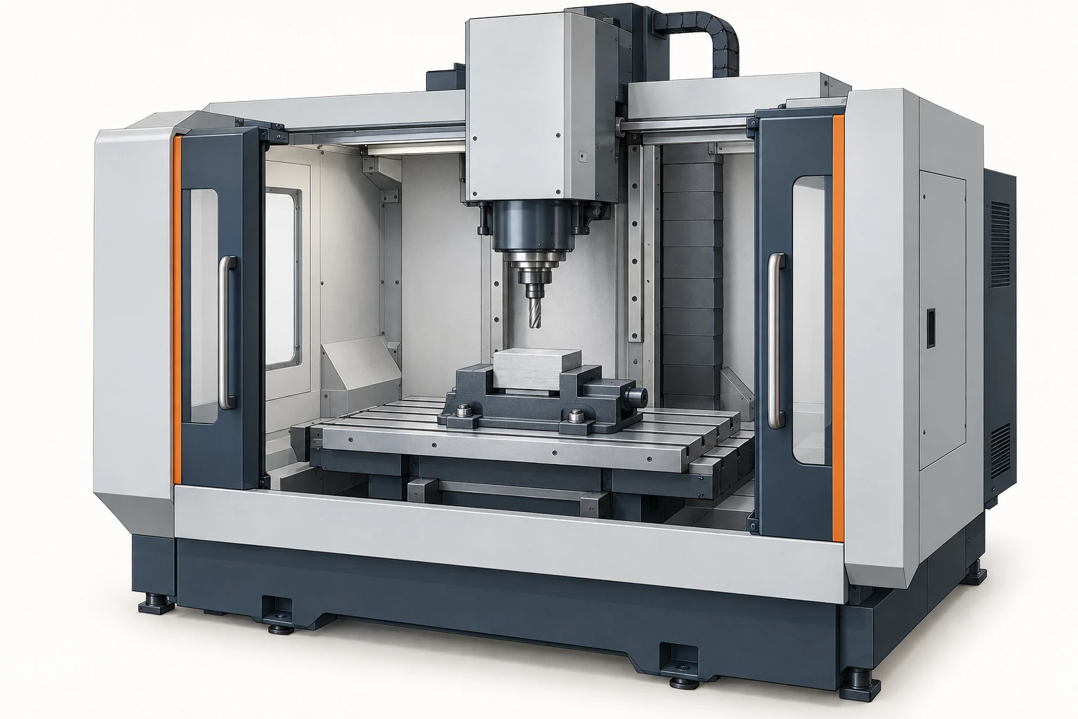
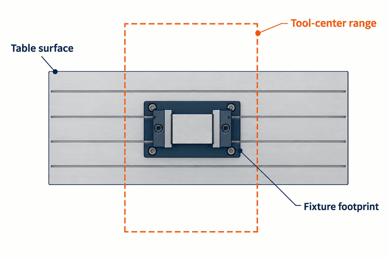
The table is longer than X travel and narrower than Y travel. Neither rectangle is a universal outline for a finished part. Overhanging stock may need additional support and enclosure clearance; a fixture can occupy table space without being machined across its full width. The milling-machine component guide explains the assemblies behind these specification labels.
For an operation, check the tool-center envelope: the smallest range that contains all required cutter-center positions, including approach and exit moves. Cutter radius and the chosen path can carry the tool center beyond the stock edge.
For example, assume a machine has 800 mm of X travel and a 760 mm-wide blank. If the planned path runs from X = −30 mm to X = 790 mm in work coordinates, it needs 820 mm. That path exceeds the available travel even though the blank is narrower than 800 mm. Moving the work offset cannot reduce the span; the path, setup orientation, tooling or machining route must change. A span that is small enough must still be positioned within the machine’s actual limits.
Build the complete vertical stack
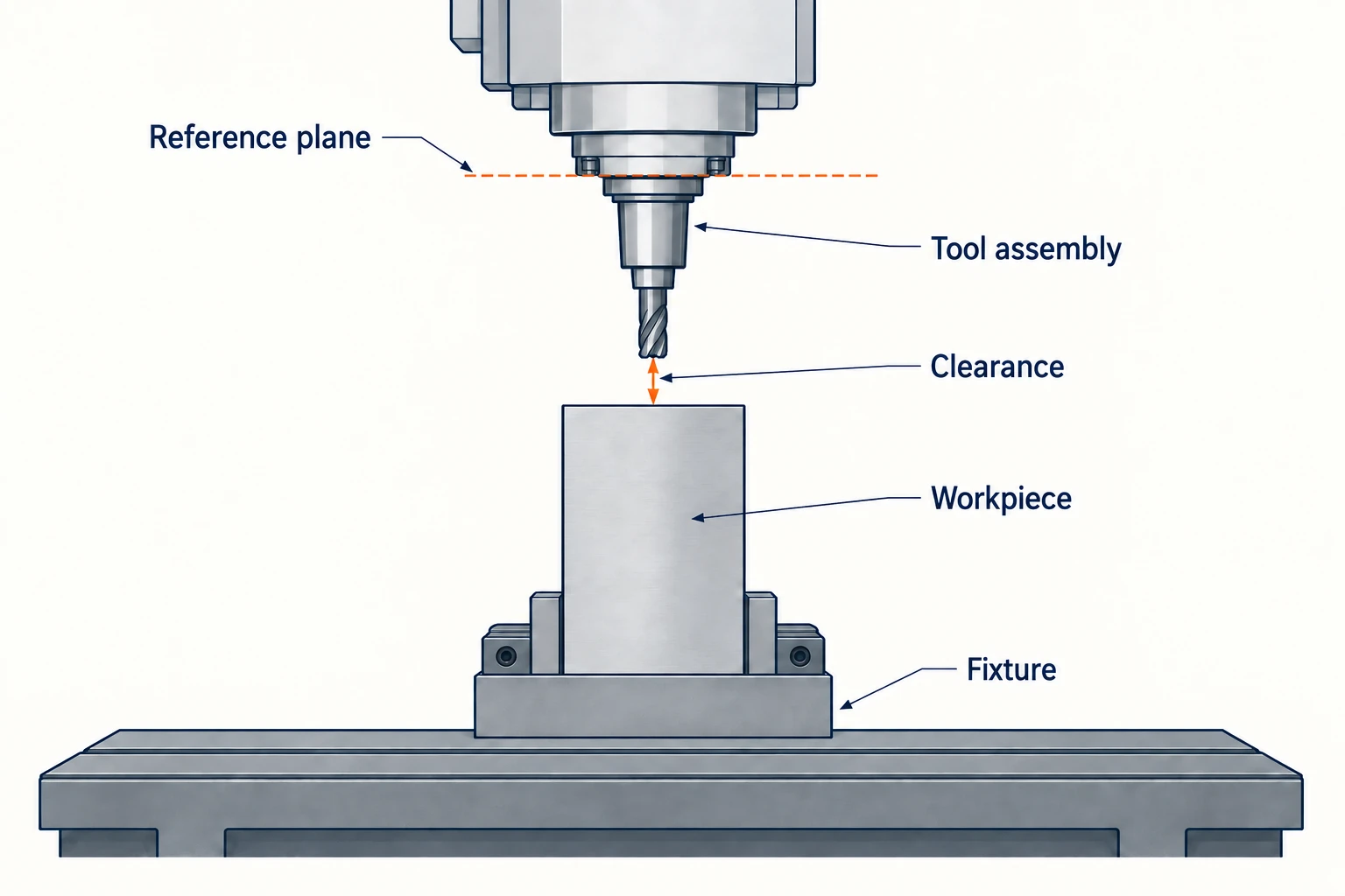
Z travel is a stroke. To evaluate height, first find the machine’s minimum and maximum spindle-to-table distances and identify their reference plane. A spindle-nose dimension and a tool length measured from the holder’s gage line cannot simply be added or subtracted unless their datum relationship is accounted for.
For a preliminary check above a flat workpiece, measure every term from compatible reference surfaces:
Required spindle-reference height = fixture support height + workpiece height + tool projection + retract clearance.
Here is a hypothetical setup, using a machine whose selected spindle reference plane can sit 100–600 mm above the table. Tool projection is measured downward from that same plane. These are teaching assumptions, separate from the VF-2 dimensions above.
| Stack item | Assumed height |
|---|---|
| Table to workpiece support surface | 80 mm |
| Workpiece above that support | 300 mm |
| Reference plane to tool tip | 180 mm |
| Tool-tip clearance above the workpiece | 20 mm |
| Required reference-plane height | 80 + 300 + 180 + 20 = 580 mm |
The height check leaves 20 mm below the assumed upper limit. Raising the fixture support to 120 mm changes the requirement to 620 mm, exceeding that limit by 20 mm without changing the part.
Also check the other end of the range: a short tool may not reach a low feature before the spindle reaches its lower limit. Repeat the calculation for the actual tools and feature heights. This one-dimensional check does not prove that the holder clears a wall, that the tool can leave a deep pocket, or that a tool change clears the setup.
Read the table-load condition, not just the weight
Count the load carried by the table: workpieces, fixtures, subplates and any additional table-mounted equipment. For example, 180 kg of stock plus 90 kg of fixture and subplate creates a 270 kg setup before other equipment is added.
The VF-2 page qualifies its maximum table load as evenly distributed. That condition matters: a compact off-center load is not equivalent to the same mass spread across the table. Check the applicable distribution and mounting limits; a rotary unit may have its own payload and moment limits as well. Those limits remain relevant when adding fourth- or fifth-axis motion.
Separate speed limits from cutting performance
Maximum spindle rpm tells you the upper speed limit. It does not tell you the torque available at the speed selected for a particular cutter. Read the torque and power curves for the installed spindle, together with their duty rating. A short-duration peak and a continuous rating support different workloads.
Haas’s 10,000-rpm Spindle specifications explicitly distinguish time-limited peak output from continuous operation. Treat the curve, operating speed and rating duration as one piece of information. Do not calculate a roughing capability from the largest horsepower number alone.
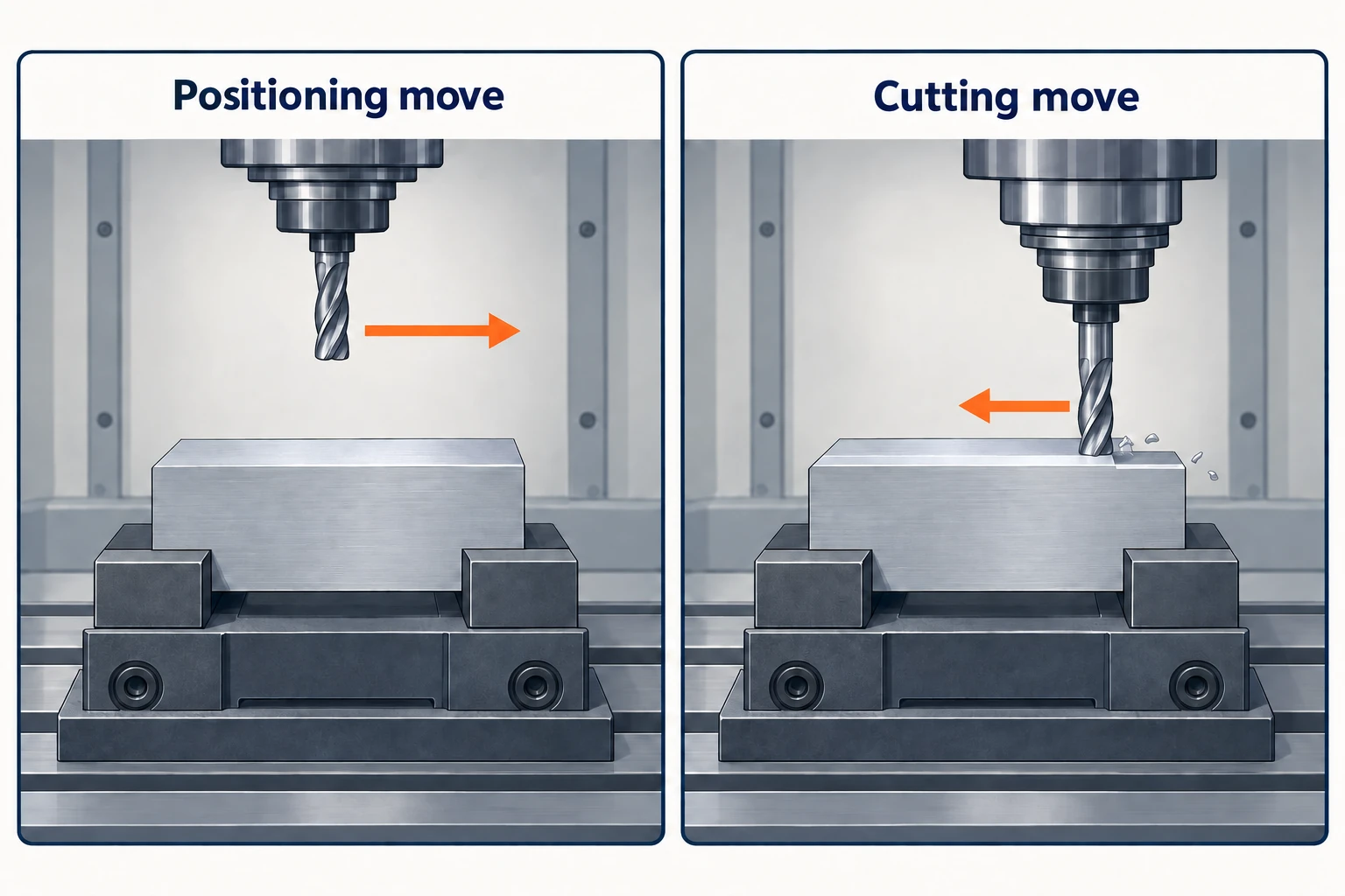
Feedrate rows need the same care. Rapid traverse is positioning motion; maximum cutting feed is a separate machine limit. The programmed cutting feed must also suit the material, tool, engagement and required finish. On short moves, acceleration and deceleration can prevent the machine from reaching its headline speed, so dividing every move distance by maximum rapid rate can understate cycle time.
Tool-pocket count is not always usable tool capacity
A magazine’s pocket count is only the starting point. Compare the complete tool list with permitted tool diameter, length and weight, and check which toolholder interface and retention hardware the machine requires.
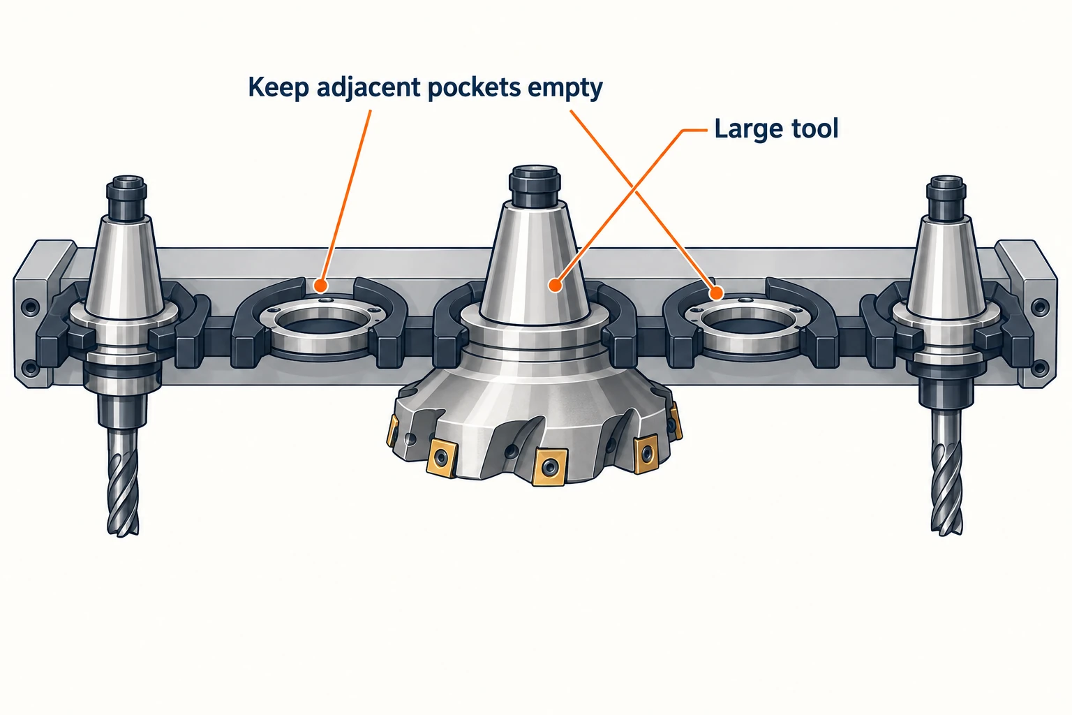
Large tools can consume clearance around nearby pockets. The Haas side-mount tool-changer manual, for example, describes large-tool assignments that keep adjacent pockets empty. That rule concerns a compatible side-mount changer; it should not be transferred automatically to a different magazine or to the VF-2’s listed standard carousel.
Tool length has two separate consequences: the assembly must fit the changer, and it must reach the feature while clearing the workpiece and fixture during machining. Passing one check does not establish the other. Likewise, a published tool-to-tool time describes a defined exchange, not every retract, positioning and spindle-speed change in a production cycle.
Positioning figures do not specify the finished part
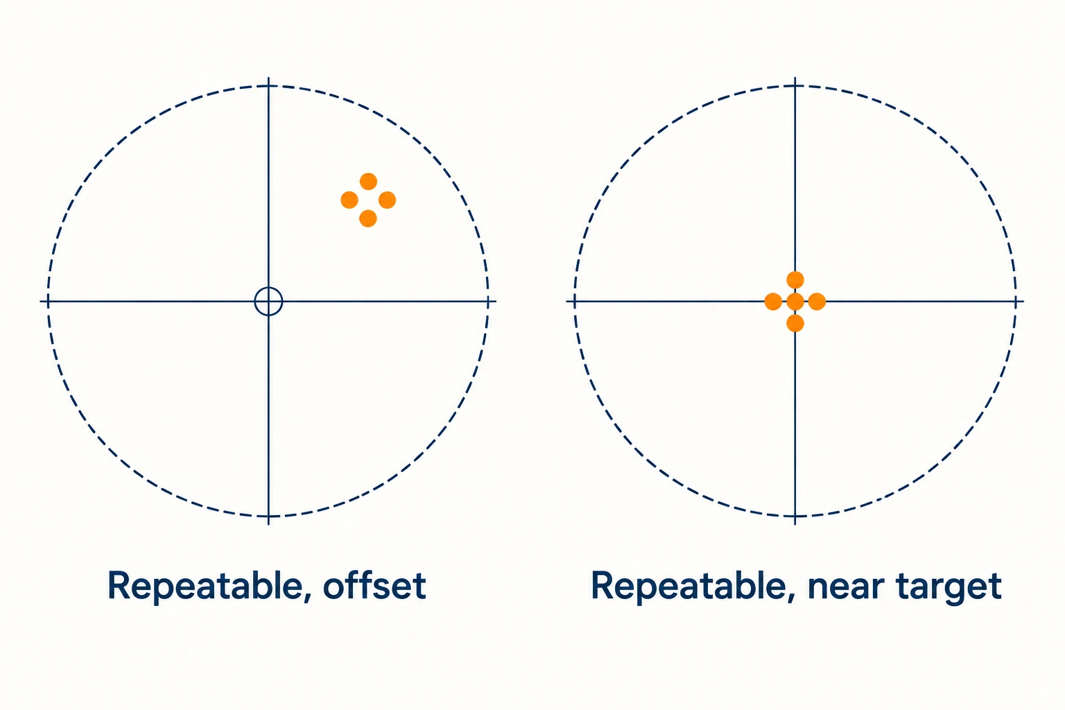
Positioning accuracy concerns agreement between commanded and achieved position under a test method. Repeatability concerns how consistently the machine returns to a position. Closely grouped returns can still be offset from the target.
When comparing figures, retain the stated test method, axis and measurement range, thermal condition, compensation state and direction of approach. A unidirectional result should not be treated as interchangeable with a bidirectional one.
Renishaw’s Process foundation guidance explains how mechanical and thermal behavior affect machine-tool accuracy. Cutting forces, tooling and workholding add influences that a positioning test does not reproduce. Use the machine specification to understand the tested motion performance; evaluate a part tolerance through the actual machining and inspection process.
A useful specification review ends with a few job-specific statements: the programmed travel fits, the complete height stack has the required clearance, the supported load meets its conditions, and the tools fit both the spindle and magazine. Keep unresolved items specific—such as a holder-to-wall clearance or an undefined power rating—so the next check addresses the actual uncertainty.
Frequently asked questions
Does XYZ travel define the largest part a VMC can machine?
No. Travel limits relative motion. Part size also depends on support, fixture placement, tool-center paths, tool and holder clearance, and the machine enclosure. A particular feature may fit within travel even when the stock extends farther, while a smaller blank may require an oversized toolpath.
Is Z travel the maximum workpiece height?
No. Read the spindle-to-table range and its reference plane, then include the fixture, part, tool projection and required clearance. Check both the upper clearance limit and the lower position needed to reach each feature.
Can a 24-pocket tool changer always hold 24 tools for a job?
Not necessarily. A large tool may require adjacent pockets to remain empty on a changer designed for that arrangement. Tool diameter, length, weight and the magazine’s specific rules determine the usable count.
Can machine repeatability be used as a part tolerance?
No. Repeatability measures consistency under specified test conditions. A finished part is also affected by tool behavior, cutting forces, temperature, workholding and inspection. Its tolerance must be assessed for the actual process and feature.


