On this page
A slender shaft can meet its diameter near the chuck and come out oversized farther along the cut. Cutting force bends the workpiece away from the tool, changing how much material is removed. If the tool and workpiece also vibrate relative to each other, the surface may develop chatter marks.
The starting point for slender shaft machining is the unsupported length at the cutting location, the shaft’s bending stiffness, and the direction and size of the cutting load. Support placement often matters more than the part’s overall length-to-diameter ratio.
How cutting force becomes a diameter error
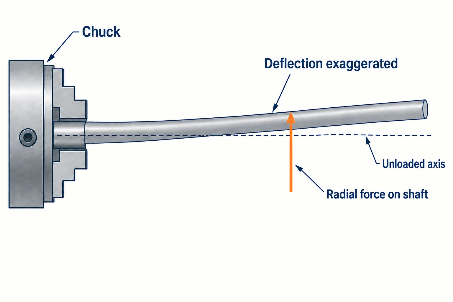
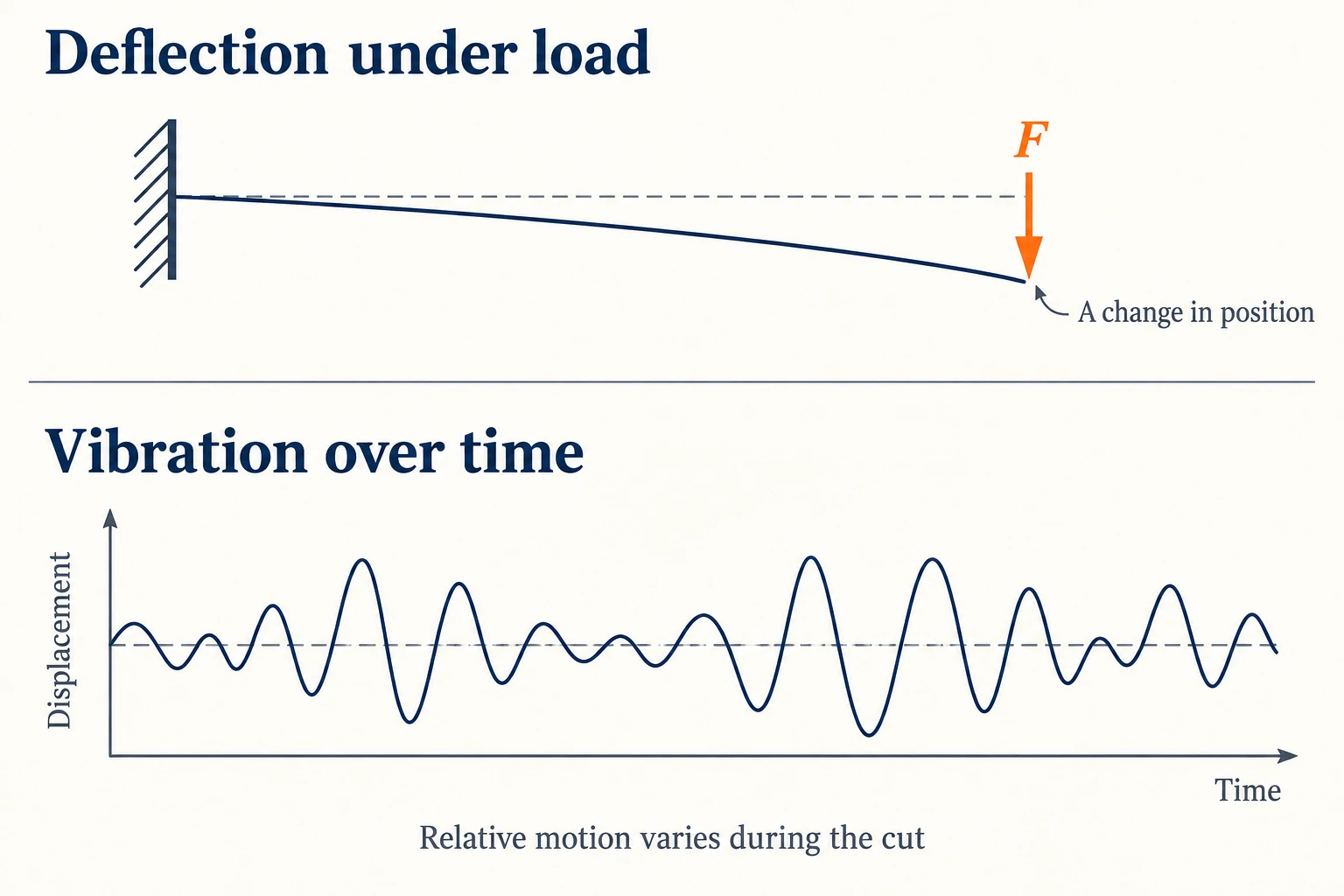
In external turning, the radial component of cutting force pushes into the shaft, perpendicular to its axis. A flexible workpiece moves away from the cutting edge. The tool and holder can deflect too, so the relevant movement is the change in position between the edge and the workpiece.
Elastic deflection largely disappears when the load is removed, but the metal left behind does not. That is why a shaft can spring back after a pass and still have a diameter error. Changing flexibility along the tool path can produce a taper or a fuller middle section, depending on the support arrangement. Those shapes are clues, not proof of a single cause.
Why a shorter unsupported length helps so much
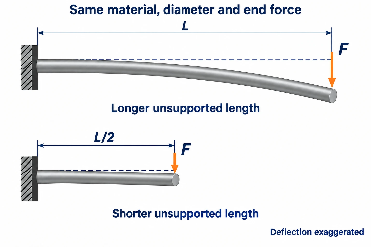
A simple beam model shows the sensitivity. For a straight, uniform shaft rigidly fixed at one end and loaded sideways at its free end, the small elastic tip deflection is:
δ = FL3 / (3EI), with I = πd4 / 64 for a solid circular section.
Here, F is the transverse end force, L the exposed length, E Young’s modulus, and d the diameter. I describes the cross-section’s resistance to bending. The relations come from cantilever beam theory and the second moment of area.
For an illustrative calculation, assume a transverse force of 20 N and a material modulus of 200,000 N/mm². All three cases below use the same ideal fixed end and end load.
| Exposed length L | Diameter d | Calculated tip deflection δ |
|---|---|---|
| 120 mm | 10 mm | About 0.117 mm |
| 60 mm | 10 mm | About 0.0147 mm |
| 120 mm | 12 mm | About 0.0566 mm |
Halving the exposed length reduces this model’s deflection to one eighth. Increasing diameter also helps strongly because it enters the equation to the fourth power. Conversely, a shaft becomes less stiff as turning reduces its diameter.
A chuck, tailstock and steady rest do not behave like this ideal fixed-end model. Steps, changing load position and flexible supports change the result. Use the calculation to understand sensitivity; it does not predict a finished diameter error or an allowable machining length.
Put support where the shaft needs it
Start by identifying the section that can bend between the cutting point and the supports. In CNC turning, this working span is part of the workholding review. A long part may have a short working span; a shorter part with a thin neck may still be difficult to hold rigidly.
| Support | What it changes | What still needs checking |
|---|---|---|
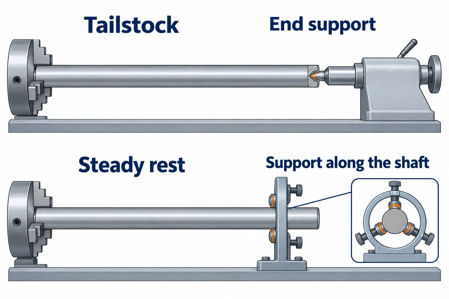
| Tailstock center | Supports the far end instead of leaving it free. | Center-hole contact, alignment, center condition and applied force. The shaft can still bend between supports. |
| Steady rest | Adds support at a selected position along the shaft. | A suitable contact surface, correct adjustment and room for the tool to reach its features. |
| Follow rest | Travels with the carriage, keeping support near the cutting region. | Rest-to-tool position, contact condition and whether shoulders or diameter changes interrupt support. |
Haas’s Toolroom Lathe Operator’s Manual Supplement describes the steady rest as added support for long or narrow shafts. The follow-rest section of Grizzly’s G0949G Gunsmith Lathe Owner’s Manual explains its role in resisting cutting-tool pressure on slender workpieces.
More tailstock force is not automatically better. Excessive force can deform the stock, while poor alignment or contact creates other errors. Haas’s tailstock troubleshooting guide treats pressure and alignment as separate checks. The correct setting depends on the actual machine, center and part.
Separate steady deflection from chatter
Deflection describes a displacement under load. Chatter is a dynamic instability in which relative tool–workpiece vibration is sustained by the cutting process. In regenerative chatter, waviness from an earlier revolution changes the chip thickness on the next, feeding back into the cutting force. Research on slender-shaft turning models the tool and shaft together because both can participate in that vibration.
A quiet cut can still leave a size error. Equally, visible periodic marks do not establish that the shaft alone is responsible; toolholding, the center and the machine also belong in the investigation.
Once the support is sound, review the cutting edge and its operating range. Sandvik Coromant’s insert guide identifies positive inserts as a useful starting point for slender components. Nose radius, entering angle, feed and depth of cut affect the force balance. A smaller nose radius can reduce vibration tendency, with a tradeoff in edge strength.
Do not keep reducing feed until the tool barely cuts. Haas’s chatter guide identifies an excessively light chip load as a possible source of instability. Select parameters within the toolmaker’s range, then evaluate controlled changes. Changing spindle speed may interrupt chatter, but it cannot remove the shaft’s static flexibility.
Measure the pattern, not just one diameter
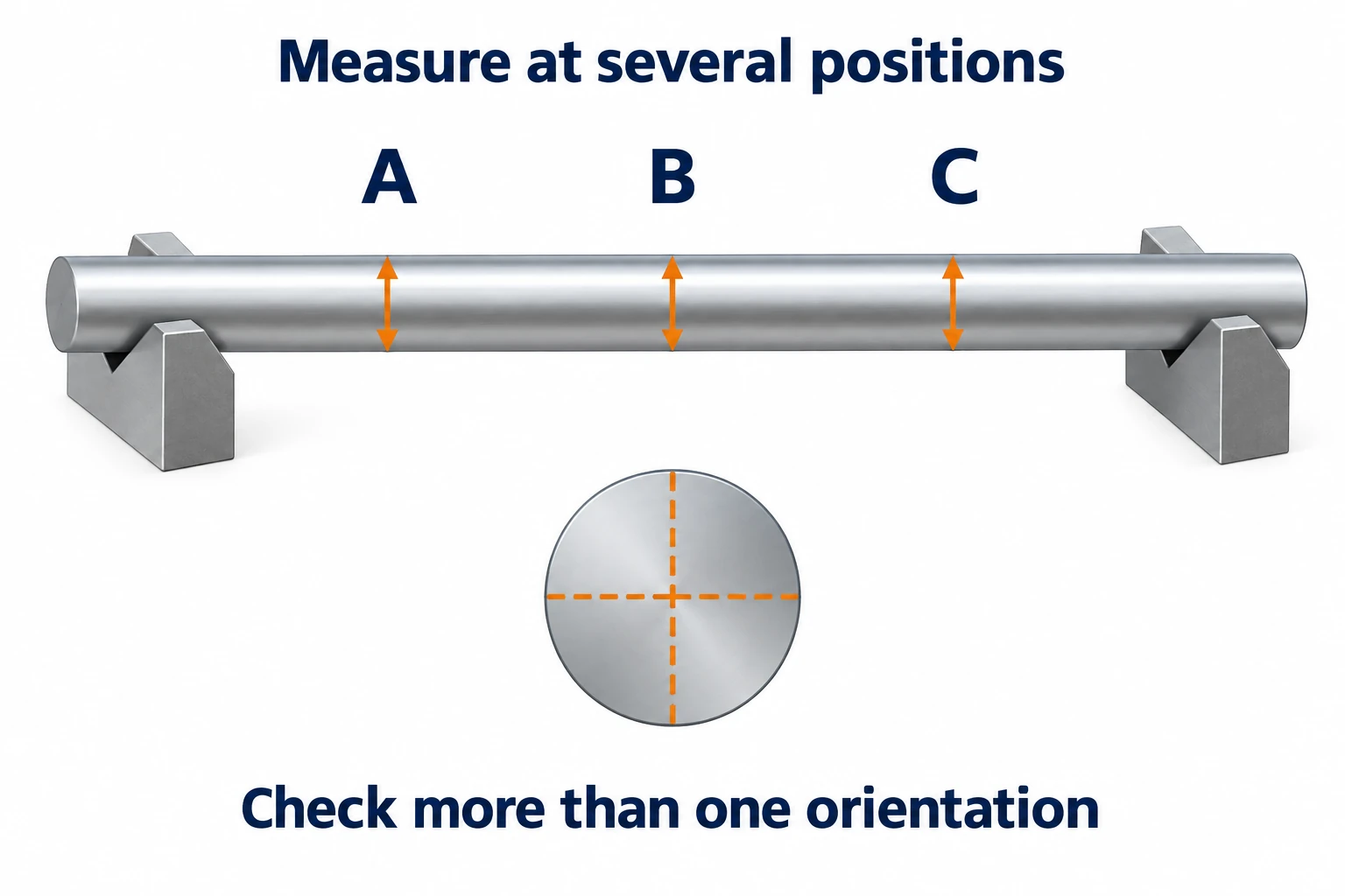
Before changing offsets, map the error along the shaft. For a nominally cylindrical section, measure diameter at several axial positions and more than one angular orientation. Record the locations so subsequent passes or parts can be compared. A single reading near the chuck can miss an error in the middle or at the far end.
Keep size, form and runout requirements separate. Two-point diameter readings help identify size variation, but cannot establish the full roundness profile. Mitutoyo’s Evaluation Methods for Roundness explains the limitations of both diameter and V-block methods. Runout is assessed relative to a datum axis, as shown in its Quick Guide to Precision Measuring Instruments; an indicator trace in an arbitrary support setup is not automatically the drawing’s specified runout result.
Record how the part is supported during inspection and whether it is still clamped, newly released or temperature-stabilized. A change between those states is useful evidence, but does not by itself identify residual stress, temperature or clamping as the cause. Use the drawing’s specified condition for final acceptance.
Use the observed pattern to choose the next check:
| Observed pattern | Possible explanation | Useful next check |
|---|---|---|
| Diameter varies with axial position, with little obvious vibration. | Load-dependent deflection, alignment or a programmed size trend. | Compare the diameter map with the support positions; verify alignment and the commanded path. |
| Periodic marks or vibration appear during part of the pass. | A dynamic problem involving the shaft, tool or support system. | Check contact and tool condition, then compare controlled speed/engagement changes. |
| Readings change after unclamping or after waiting. | A change in restraint, thermal condition or material stress state. | Repeat with a documented support and temperature condition before applying an offset. |
| Diameter readings appear consistent, but indicator variation remains. | Size alone has not resolved form, axis location or the inspection setup. | Check the datum setup and measure the specified geometric characteristic. |
A useful correction should match the cause: change support for a flexible span, investigate the dynamic system for chatter, and resolve the inspection setup before interpreting runout.
Frequently asked questions
What length-to-diameter ratio makes a shaft difficult to machine?
There is no single ratio that defines difficulty for every shaft. The unsupported span during the cut, local diameter, material stiffness, cutting load and support arrangement all matter. Overall length divided by the largest diameter can hide a flexible neck or a long exposed section.
Why can a slender shaft still chatter with a tailstock?
A tailstock supports the end, but the shaft can still flex between supports. Chatter can also involve the tool, center contact or machine. Check the center’s condition and alignment as well as the tool and cutting parameters; simply adding tailstock pressure may deform the part.
Does reducing feed always reduce shaft deflection?
No. Feed affects cutting load, but an excessively light chip load can produce an unstable cut. Support, insert geometry and depth of cut must be considered together. Use the toolmaker’s application range, then compare changes against both the surface condition and the measured diameter pattern.
Can a shaft have the correct diameter but still fail a runout requirement?
Yes. Diameter readings alone do not establish the surface’s relationship to the specified datum axis. Verify the required geometry using an appropriate datum setup and inspection method. Repeated two-point diameter measurements also cannot prove that every cross-section is round.


