On this page
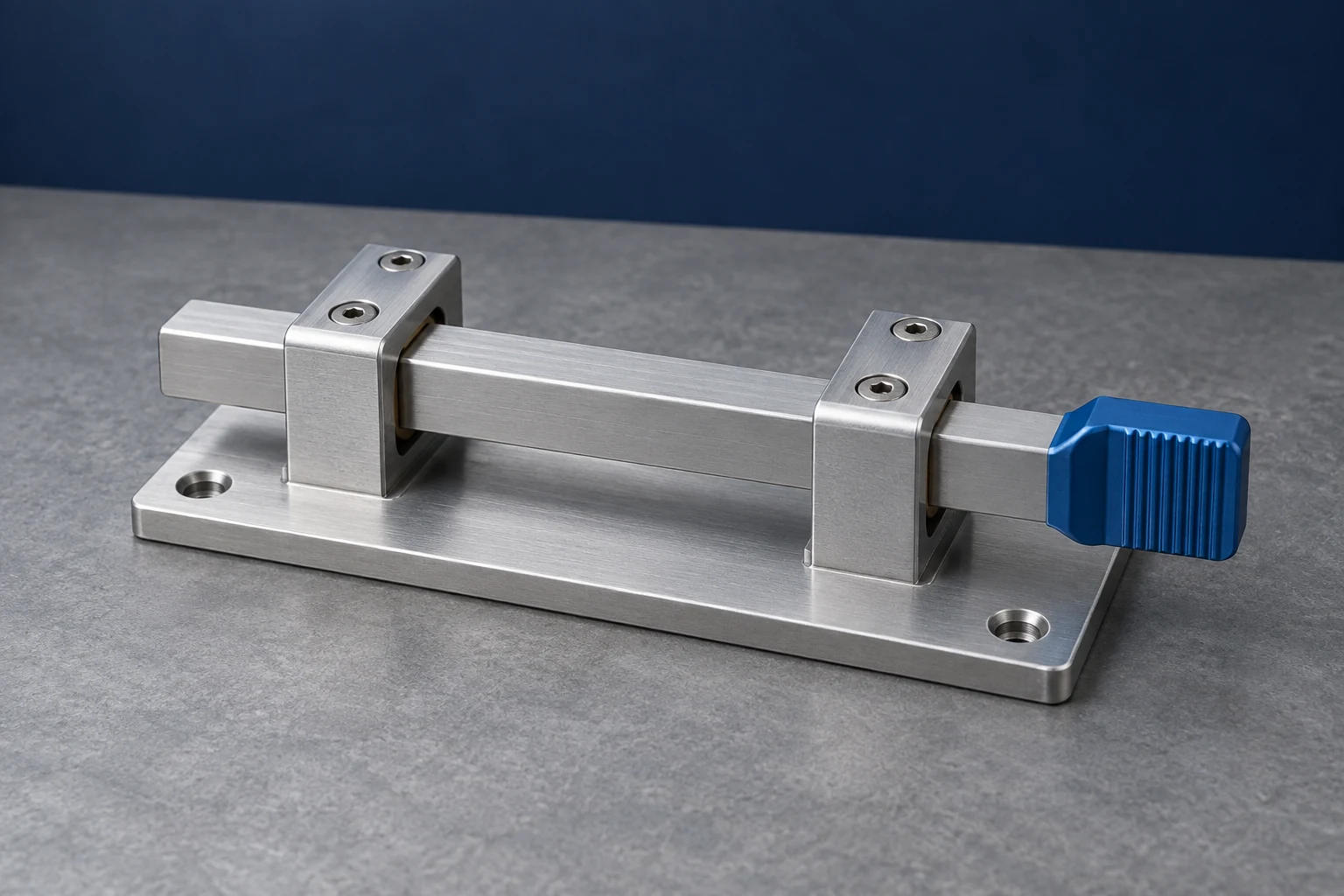
A proof-of-concept prototype tests whether a proposed idea or mechanism can work. An appearance prototype represents the product’s visible form. A functional prototype supports a specified test of behavior, which may involve only one component or subsystem. A finished-looking model can therefore be less useful for a load test than a rough, open assembly.
For a CNC part, define the question before ordering the sample: movement, access, fit and resistance to load require different prototype characteristics. The label on the order should describe that purpose, not imply that every aspect of the design has been tested.
Concept, appearance and functional prototypes
Prototype terminology varies across engineering teams. The categories below describe useful purposes rather than a mandatory sequence of development stages. A literature review published by the Design Society documents this variety of definitions and strategies. [1]
| Prototype purpose | Main question | What it needs to represent | What the label alone does not establish |
|---|---|---|---|
| Proof of concept | Can this principle or mechanism work? | The elements necessary to demonstrate the proposed behavior | Final appearance, durability or manufacturability |
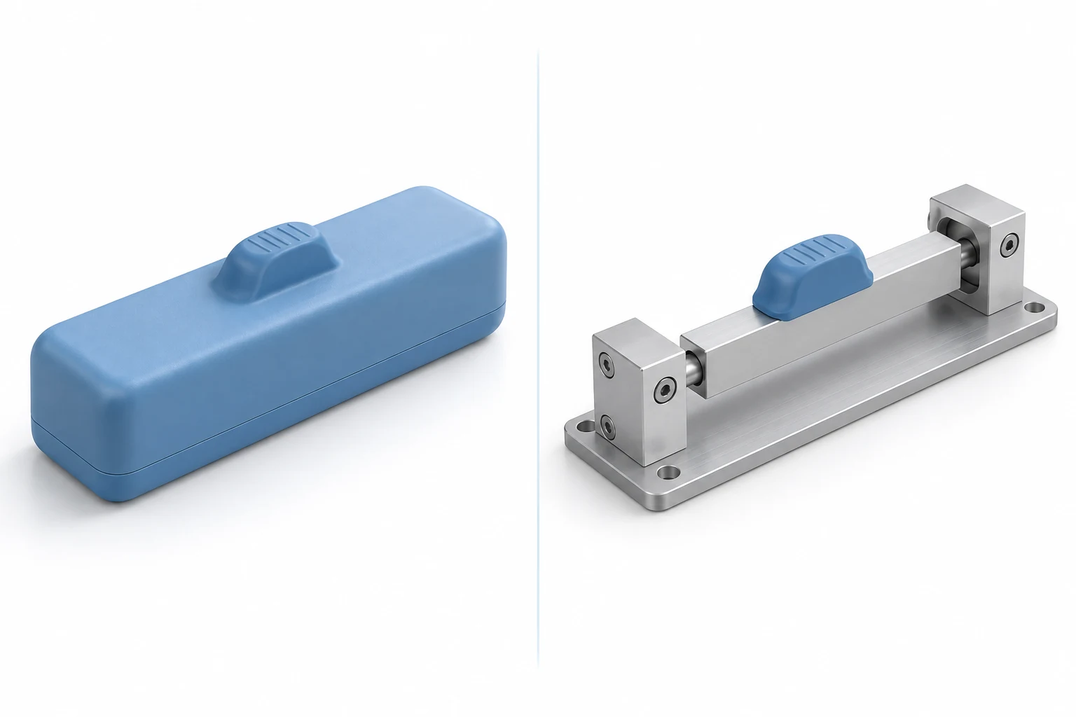
| Appearance / looks-like | Does the form communicate the intended product? | Relevant shape, size, surface and visual details | Internal operation or load capacity |
| Usability / feels-like | Can the intended user handle and operate it as planned? | Relevant grip, access, weight, balance and interaction | Unrepresented operating forces or internal performance |
| Functional / works-like | Does the selected function meet its test objective? | The features and conditions that govern that function | Untested functions, environments or production consistency |
These purposes can overlap. An early mechanism demonstrator is both a proof of concept and a limited functional model. Stanford’s prototyping guidance explicitly allows a works-like prototype to represent just one aspect of a design; it need not resemble a complete product. [2]
Match prototype fidelity to the question
Fidelity describes how closely a prototype represents the design in the aspects being studied. It is not one overall quality score. A model can reproduce the outside dimensions accurately while using different materials and omitting the internal mechanism.
Identify which characteristics influence the result:
- Geometry: the interfaces, travel, clearances and mounting locations needed for the check.
- Material and condition: the properties, treatment and contact surfaces relevant to the behavior.
- Assembly: the mating parts, supports and fasteners that affect alignment or load transfer.
- Operation: the forces, speed, repeated use and environment included in the test.
Keep these characteristics representative; simplify features that do not affect the question. MIT’s design course distinguishes models sufficient to study movement geometry from those needed to study dynamic behavior. The right level of detail depends on the experiment. [3]
For example, checking whether a cover blocks a thumb grip does not require a full endurance program. Measuring wear at that grip’s sliding interface does require attention to the contacting materials and operating conditions. The materials and part-design guide explains how grade, condition and environment enter a part specification.
One sliding bolt, three different questions
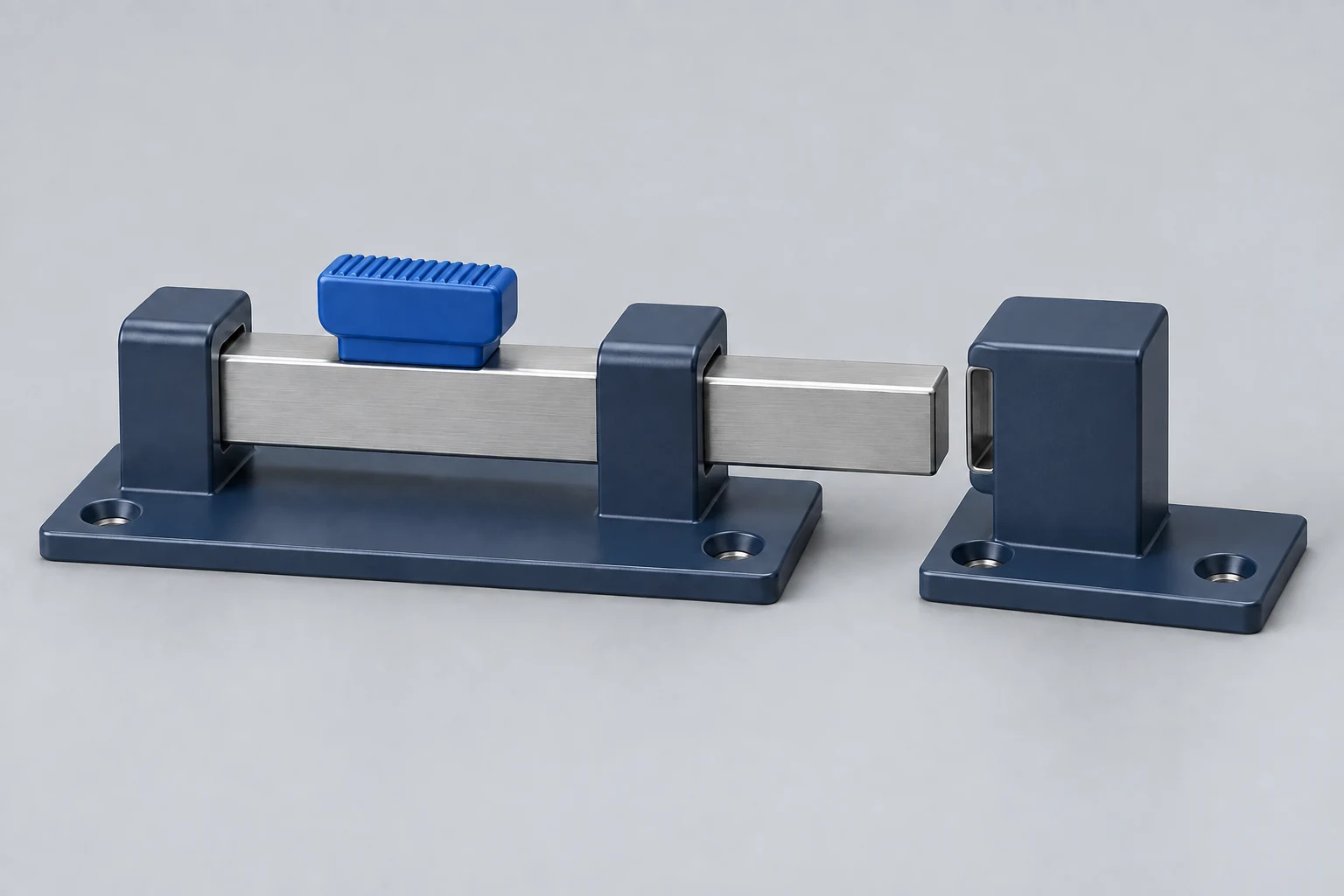
Consider a hand-operated sliding bolt for a small access panel. The bolt moves through guides into a keeper attached to the surrounding frame. Its development models can look quite different depending on the unresolved question.
Can the bolt reach and clear the keeper?
A proof-of-concept assembly can expose the mechanism and omit the decorative cover. Preserve the relative locations of the guides and keeper, the bolt’s travel and any stops. Observe whether the bolt enters, withdraws and clears the panel through the intended motion. This establishes movement for that arrangement; it does not establish a holding-load rating.
Can the user reach and move the grip?
An exterior model should reproduce the cover, grip location and nearby panel edges. If gloves are part of intended use, include that condition in the evaluation. A fixed grip may reveal access problems, but it cannot establish operating effort. To study effort, the model must reproduce the resistance the user needs to overcome.
Will it hold and release under the specified conditions?
A functional assembly for this question needs the relevant bolt and keeper geometry, contact materials, guides and mounting arrangement. Define the applied load and direction, how the panel and frame are supported, and whether release is tested while loaded or after unloading. Measure retention and release effort against the design’s criteria. If repeated operation matters, specify that test separately; opening the bolt once does not establish service life.
Combining the checks into one sample may be sensible once the necessary geometry is settled. Earlier, separate models can expose a movement or access problem before the complete assembly is built. The test purpose determines which simplifications remain acceptable.
Write a test brief that identifies the sample
Use a short engineering record alongside the drawing. NASA’s verification and validation planning guidance calls for identifying test articles and defining which activities each will undergo. Its aerospace program structure is specific to that context, but identifying the tested object and scope is useful in ordinary prototype work too. [4]
- Question and decision: what uncertainty this build addresses and what result would justify the next design choice.
- Sample identity: part, revision, quantity, materials and any deliberate differences from the intended product.
- Setup and conditions: mating components, mounting, loading, environment and preparation needed for this test.
- Observation or measurement: what will be recorded, by which method, and the acceptance criterion where one applies.
- Result and limits: what happened, which conditions were actually tested, and what remains unresolved.
For machined samples, our CNC prototyping and production service page describes the manufacturing order stages. Keep the sample’s engineering test brief distinct from its purchasing and delivery requirements.
Keep the conclusion within the test
“The prototype works” is too broad to guide the next build. A useful result identifies the tested revision, observed behavior and conditions. For the sliding bolt, report engagement, retention and release findings separately instead of combining them into one overall approval.
If a sample fails, first check whether its actual dimensions, material, assembly and setup match the planned test. A manufacturing error or an unintended substitution can obscure the design question. If it passes, identify which unresolved question deserves the next test.
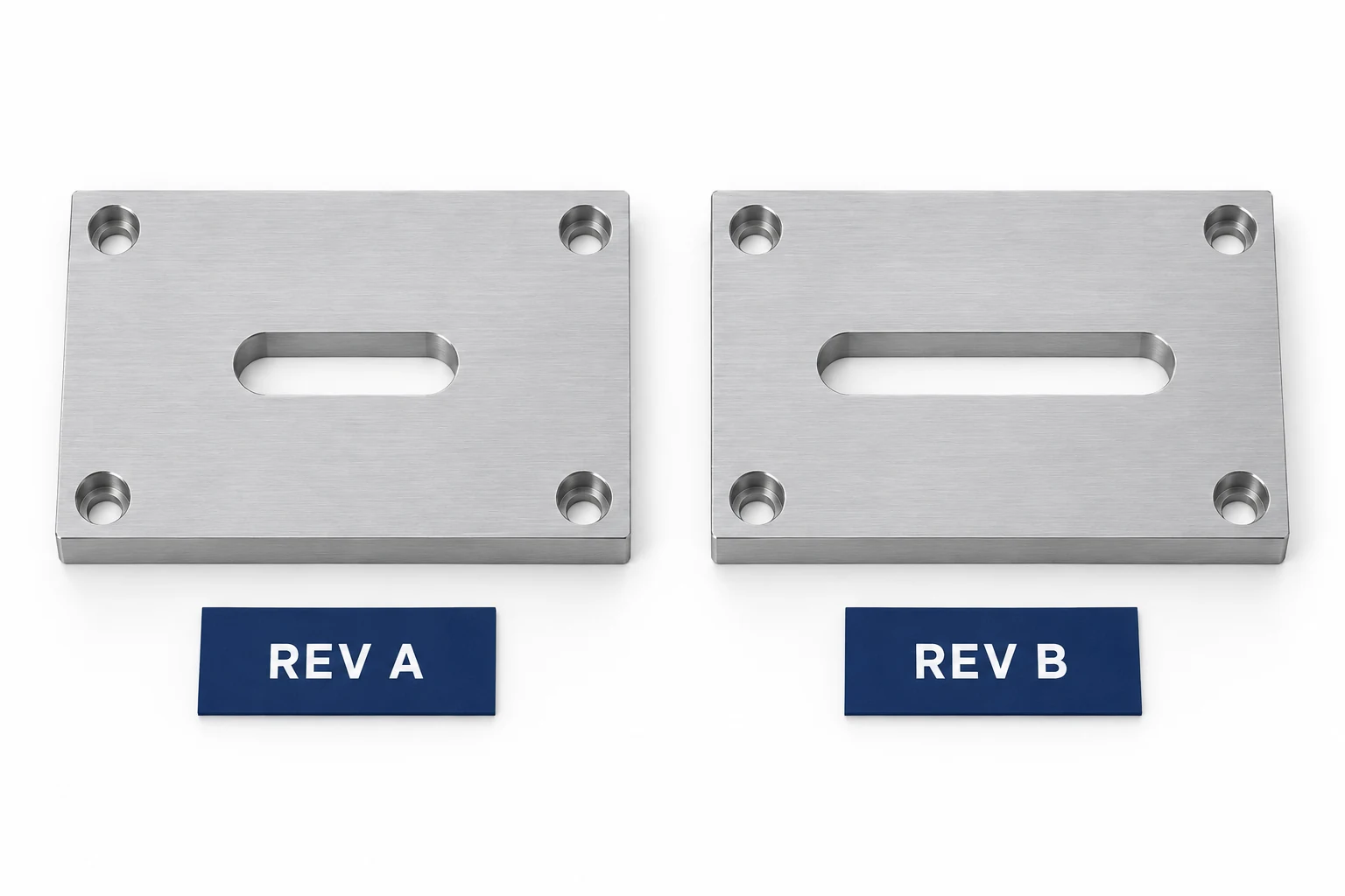
Retain the tested configuration as the design changes. Stanford’s guidance emphasizes documenting interim builds so that later comparisons have a reliable reference. [2] Once attention shifts from the individual design to repeat manufacture, use a separate production-readiness review; the prototype-to-production guide covers that transition.
Questions about prototype types
Can a proof of concept also be functional?
Yes. A proof of concept can demonstrate a specific working mechanism. Calling it functional should identify which behavior it represents, rather than imply that the entire product has been validated.
Is every CNC prototype a functional prototype?
No. CNC machining describes how the part is made. Its geometry, material, assembly and test purpose determine whether it is an appearance model, a fit-check sample or a functional test article.
Must every prototype use the final material?
No. A substitute may be adequate for a shape or access check. When the result depends on material behavior, preserve the relevant grade, condition and processing effects or explicitly limit the conclusion.
Sources
- Jensen, Özkil and Mortensen, Prototypes in Engineering Design: Definitions and Strategies, 2016, definitions and prototyping choices.
- Stanford Biodesign, Prototyping: Build V1, 2021, prototype purposes and interim documentation.
- MIT OpenCourseWare, D-Lab II: Design — Implementation, 2010, subsystem experiments and testing.
- NASA, Systems Engineering Handbook, Appendix I, test articles and verification/validation planning.


