On this page
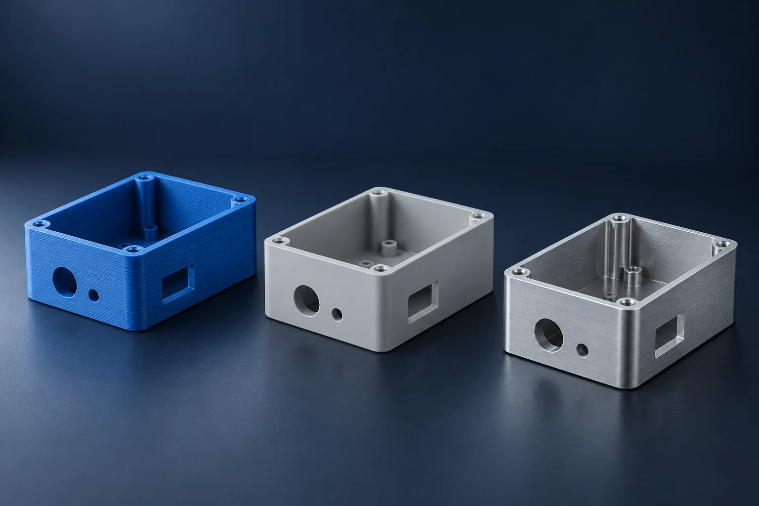
Rapid prototyping uses short design-and-build cycles to turn an idea into a physical part that can answer a specific question. Common methods include FDM, SLA and SLS 3D printing, CNC machining, urethane casting and prototype tooling. The useful choice depends on what the next sample must show: shape, assembly fit, material behavior or the production process.
A printed model may reveal an access problem before any metal is cut. A machined sample may be more useful when the test needs a specified metal or stock plastic. Neither result automatically validates a later molded or cast part. Choose the method around the evidence you need from this build.
How the main rapid prototyping methods differ
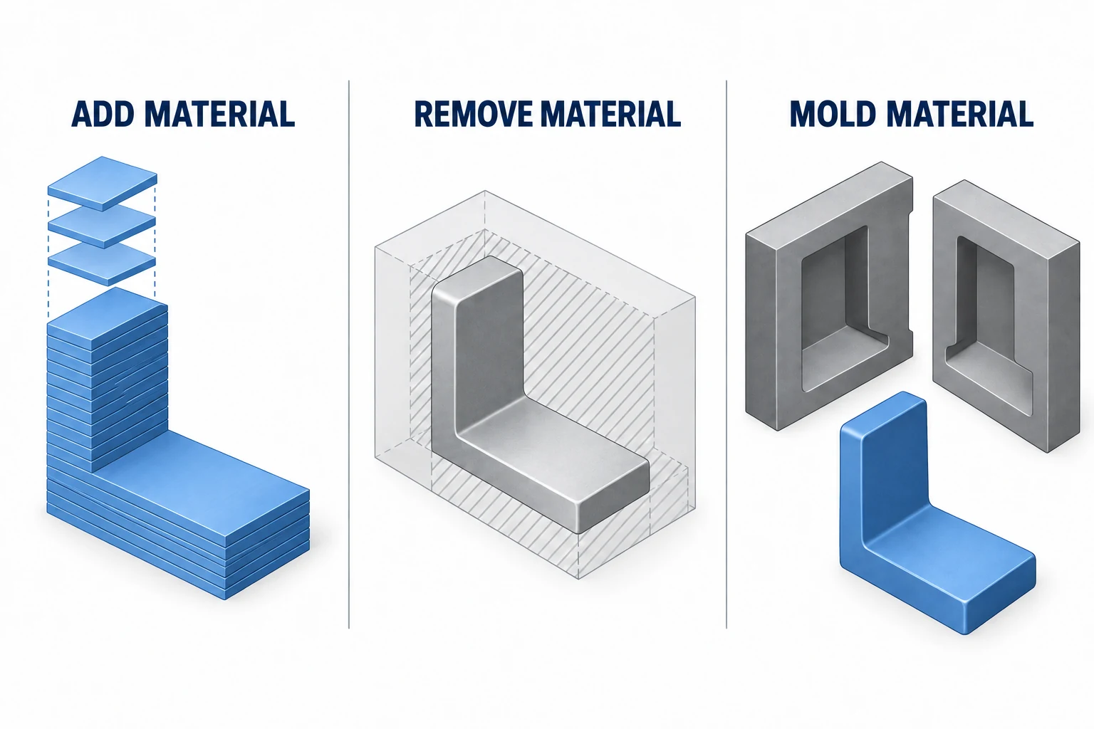
The routes differ in how they form the part. Additive manufacturing builds material layer by layer; machining removes it from a blank. Tooling routes first create a mold or pattern, then use that tool to make the sample. These differences affect geometry, materials and the work needed before testing. [1]
| Method | Useful starting application | Check before relying on the result |
|---|---|---|
| FDM / FFF: extruded thermoplastic filament | Early packaging, access and assembly models | Layer direction, support contact and the actual printed material |
| SLA: light-cured liquid resin | Fine features, appearance and selected functional checks | Resin properties, support removal and required post-curing |
| SLS: laser-fused polymer powder | Complex polymer components and functional assemblies | Material grade, powder removal and the finished interfaces |
| CNC machining: cutting stock material | Specified metal or plastic stock; machined mating features | Tool access, holding, material condition and final finish |
| Urethane casting in a silicone mold | Several copies from a master pattern | Master quality and whether the casting resin suits the test |
| Prototype injection tooling | Molded samples in the selected thermoplastic | Tool design, processing conditions and differences from the production tool |
FDM is also commonly called fused filament fabrication, or FFF. SLA uses a photopolymer resin; SLS uses surrounding unfused powder to support the build. Their feedstocks and processing steps are not interchangeable. The table summarizes method choices, rather than ranking every machine by accuracy or speed. [2]
Rapid tooling makes the tool, not the finished part directly. A CNC-machined mold insert or a printed forming tool can therefore support another manufacturing process. Tool material, temperature and loading still limit where it can be used. [3] Silicone molds and urethane samples are a separate route from injection molding a production thermoplastic. [4]
Other designs may call for sheet fabrication, thermoforming or metal additive manufacturing. Start with the manufacturing family that can reproduce the feature and material behavior being studied. The CNC machining basics guide explains the subtractive route in more detail.
Choose the method around the test question
Write the next decision as a question before choosing a process: “Can the connector be installed?” is different from “Will the support remain stiff under load?” The first may need accurate access geometry; the second also depends on material, manufacturing condition, fastening and the applied load.
For a bearing support, a polymer model can help check the mounting envelope and assembly sequence. To evaluate deflection of a specified aluminum design, a sample in the intended alloy and condition is a more relevant starting point. Even then, the test must use representative supports and loads. A fit check alone cannot establish stiffness.

Keep a short statement of what must match production and what may differ. Relevant items include the geometry, material grade, heat-treatment condition, build orientation, finish and assembly hardware. Include only those that affect the question being tested. MIT’s prototyping overview similarly starts from the required model, input data, material, tolerances, quantity and timing. [4]
A familiar material name is not enough to transfer all properties between processes. NIST’s work on additive materials examines how feedstock, process parameters, machines and build environments affect the resulting material. [5] Check applicable data and test conditions rather than assuming a printed or cast substitute behaves like the specified stock material.
From CAD to a useful test result
- Define the question and acceptance check. State what observation or measurement will support the next design decision. Identify the mating parts and environment needed for the test.
- Prepare the design for the selected route. Keep the model and drawing at one revision. Resolve tool access for machining, orientation and supports for printing, or release and filling requirements for molding.
- Prepare the manufacturing instructions. Printing uses a sliced build; CNC uses suitable toolpaths and machine instructions; a tooling route needs its tool definition before parts can be made.
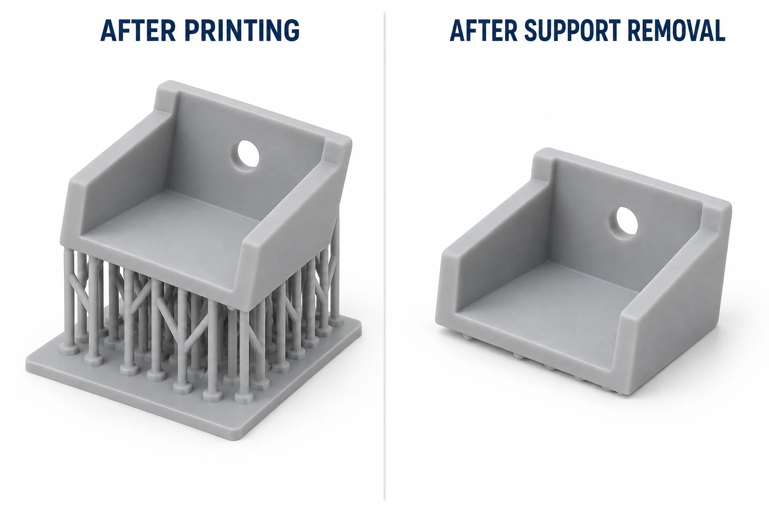
- Complete the sample’s required condition. Depending on the route, this may include removing supports or powder, washing and curing, machining interfaces, deburring or finishing.
- Inspect, test and record the decision. First confirm that the sample is suitable for the planned test. Record the result, the revision and any sample-only differences, then retain or revise the design.
Preparation and post-processing belong in the plan from the start. A printed sample still on its supports is not necessarily ready for an assembly check, and removing supports does not replace any washing or curing required for its resin. Follow the relevant material and equipment instructions. [6]
Compare the time to an answer
Machine run time is only one part of the schedule. Compare design preparation, queue time, stock or tool availability, fabrication, post-processing, inspection and delivery. A process that builds quickly can still be a poor choice if the sample needs extensive cleanup before the critical interface can be checked.
For each feasible route, compare the total cost of the required test-ready quantity. Include programming or tooling, material, finishing and inspection. Keep optional cosmetic work separate when appearance is not part of the test. The machining cost guide explains how setup and recurring work contribute to a CNC quotation.
Also consider the likely next revision. A mold made before the mounting geometry is settled creates a different commitment from a directly produced sample. Several identical samples can justify preparation that would make little sense for one shape check, but there is no universal quantity at which one method becomes cheapest.
Use the result to plan the next build
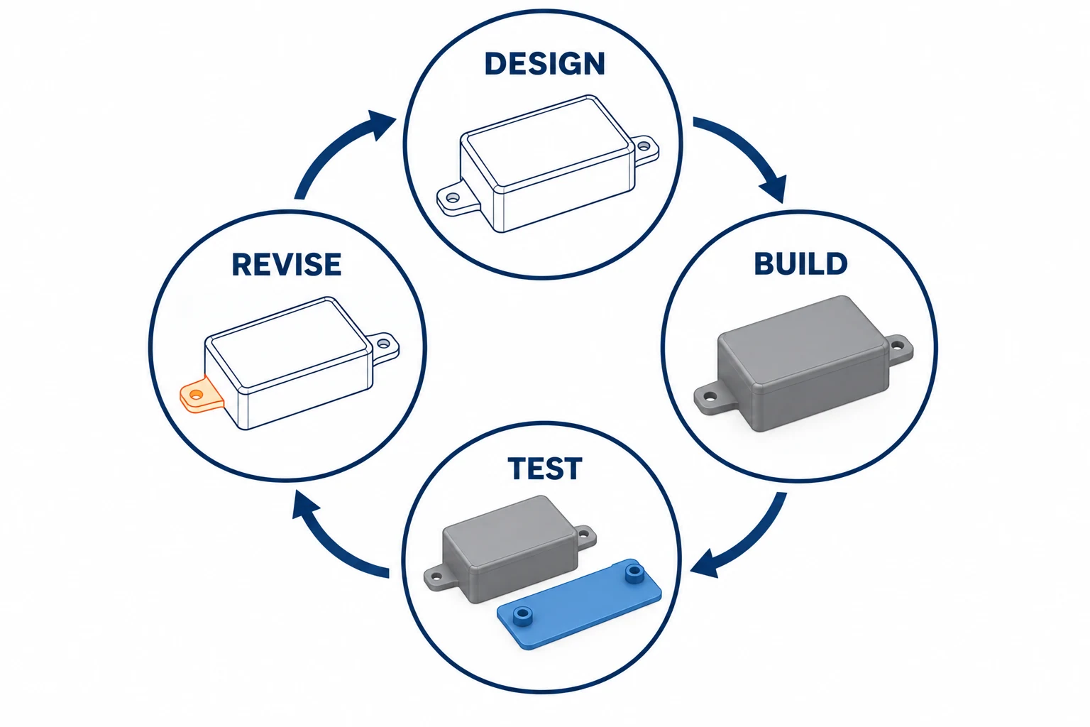
Rapid prototyping is useful when each build reduces a specific uncertainty. If the sample reveals an interference, revise the affected feature and repeat the relevant check. If it answers the question, move to the next unresolved requirement rather than reproducing the same demonstration.
Before production, identify what the prototype did not represent. A machined plastic part does not reveal how the proposed injection mold fills or releases. A successful single sample does not show the variation across a batch. MIT’s design-and-manufacturing project explicitly connects CAD decisions with tooling, molded parts and measured production results. [7]
For the CNC route, our prototyping and production service page sets out the sample, pilot and repeat-order stages. Once the design is ready for that transition, the prototype-to-production guide covers trial planning, release records and changes between batches.
Questions about rapid prototyping
Is rapid prototyping the same as 3D printing?
No. 3D printing is one family of methods used for rapid prototyping. A physical development program can also use CNC machining, casting or prototype tooling when those routes better suit the material and test.
Does a prototype need the final production material?
Only when the question depends on it. A shape or access model may use a substitute. Tests of stiffness, heat response, wear or chemical exposure need representative material and processing conditions; document any differences before interpreting the result.
Which prototyping method is fastest?
The fastest useful route is the one that delivers a sample fit for the planned test soonest. Compare the full preparation, manufacturing and finishing sequence, including availability and delivery, rather than a machine’s build time alone.
Sources
- NIST, What Is Additive Manufacturing?, process definition.
- Formlabs, What Is Rapid Prototyping? Methods, Tools and Examples, method descriptions.
- Formlabs, Rapid Tooling, tool purpose, processing requirements and material limits.
- Allison Rae, Prototyping Overview, MIT OpenCourseWare, 2006, model purposes and planning questions.
- NIST, Characterization of Additive Manufacturing Materials, process and material-property relationships.
- Stratasys, Rapid Prototyping: Methods, Benefits & Process Guide, manufacturing preparation and post-processing.
- MIT OpenCourseWare, Design and Manufacturing II: Yo-Yo Project, Spring 2025, design-to-production review.


