On this page
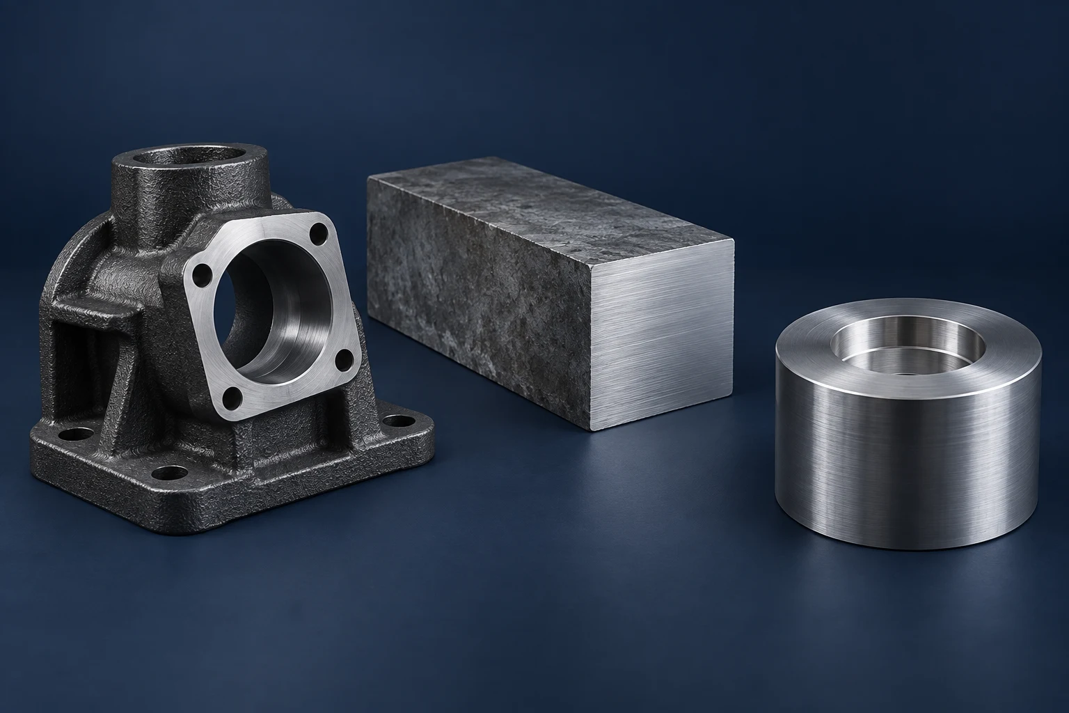
Gray cast iron often breaks into short chips more readily than steel, but “cast iron” is too broad a description for choosing a milling process. Ductile iron, its heat-treated variants and gray iron can put very different demands on a cutting edge. Identify the grade, condition and blank first; then choose tooling, cutting data and coolant for that combination.
This comparison focuses on gray and ductile irons versus carbon and low-alloy steels. The underlying CNC milling process stays the same. What changes is how the material separates, wears the tool and behaves at the finished edge.
Graphite shape changes how cast iron cuts
Gray iron contains graphite flakes within a metallic matrix. Ductile iron—also called nodular or spheroidal graphite iron—contains rounded graphite particles. The surrounding matrix matters too: ferrite and pearlite do not give the same machining response. A material name without its grade and condition leaves that distinction unresolved. [1]
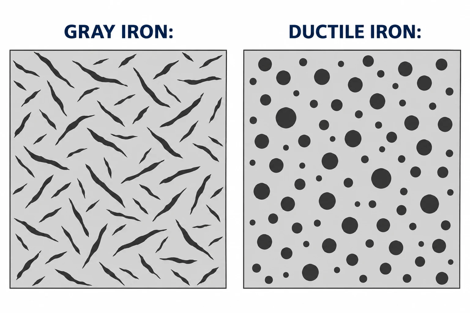
Graphite helps interrupt chip formation. Dura-Bar’s machining guide illustrates fine gray-iron chips and controllable ductile-iron chips from its continuous-cast grades, compared with longer steel chips. That is useful evidence for those materials, not proof that every steel makes stringy chips or every iron is easy to machine. Tool geometry, engagement and material condition still matter. [2]
| Material condition | Main milling concern | What to establish first |
|---|---|---|
| Gray cast iron | Abrasive wear; breakout at an unsupported exit edge | Grade, matrix, hardness and blank quality |
| Ferritic or ferritic-pearlitic ductile iron | Can cut more like low-alloy steel than gray iron | Actual structure and applicable cutter recommendations |
| Pearlitic ductile iron | Greater abrasion can change insert choice | Wear resistance as well as edge toughness |
| Soft, low-carbon steel | Adhering material at the edge; burrs | Grade, condition and chip formation |
| Harder alloy steel or heat-treated iron | Different edge-load and wear requirements | Hardness at the machining stage |
These are starting distinctions, not a ranking of all grades. Sandvik Coromant separates these material groups in its milling guidance. [3] For a material substitution, first establish that the new material meets the part’s functional and environmental requirements; easier cutting alone is not a design approval.
The first cut depends on the blank
A shaped casting, continuous-cast bar and steel billet do not start with equivalent surfaces or stock allowances. On a casting, identify the locating surfaces, variable stock and areas that must clean up completely. Check for adhering sand, scale and visible defects before treating a poor first cut as a feed-rate problem. ASTM A48/A48M addresses these surface conditions for gray iron castings. [4]
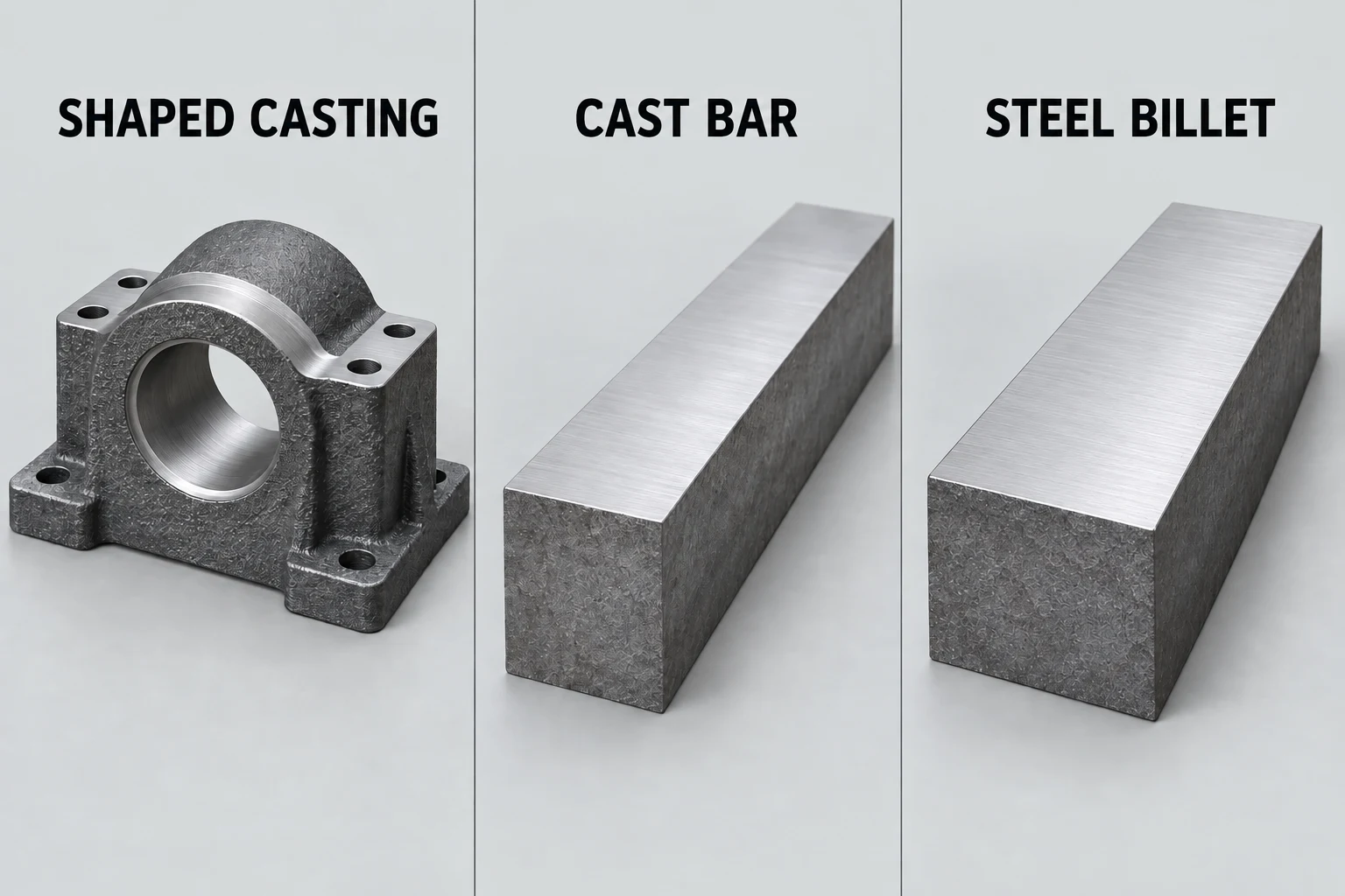
Continuous-cast stock has its own grade-specific recommendations. Dura-Bar explicitly limits its published cutting data to its engineered iron grades; uncontrolled carbides and inclusions can make the same data unsuitable for other iron. Do not transfer a bar-stock trial to an unidentified casting. [2]
For a bearing housing, record whether the bore and mounting feet arrive as cast, pre-machined or already finished. That changes the setup and remaining work even when the final drawing is identical. The cast iron machining page covers the blank and finished-part information needed for an order.
Choose tooling and coolant together
For gray-iron rough milling, coated carbide and dry cutting are common starting choices. A more pearlitic ductile iron may require greater abrasion resistance, while ferritic ductile iron can call for tooling closer to a steel application. Match the insert grade and geometry to the actual material subgroup rather than selecting a tool from the word “iron.” [3]
Milling repeatedly moves each cutting edge into and out of contact. Cutting fluid can increase the thermal cycling of a hot edge; in other situations it helps flush dust or support finishing. Sandvik’s dry-milling guidance discusses both effects. If a wet process is selected, the tool must suit it and the fluid supply must be adequate. “Always dry” and “always use coolant” both skip the application decision. [5]
Dura-Bar also publishes coolant recommendations for its stock, illustrating why a material supplier’s advice must be read alongside the cutter maker’s application guidance. Neither source supplies a universal recipe for an unknown casting. [6] Record the tool, material condition, engagement and coolant mode together when setting the trial’s starting parameters.
Distinguish edge damage from surface texture
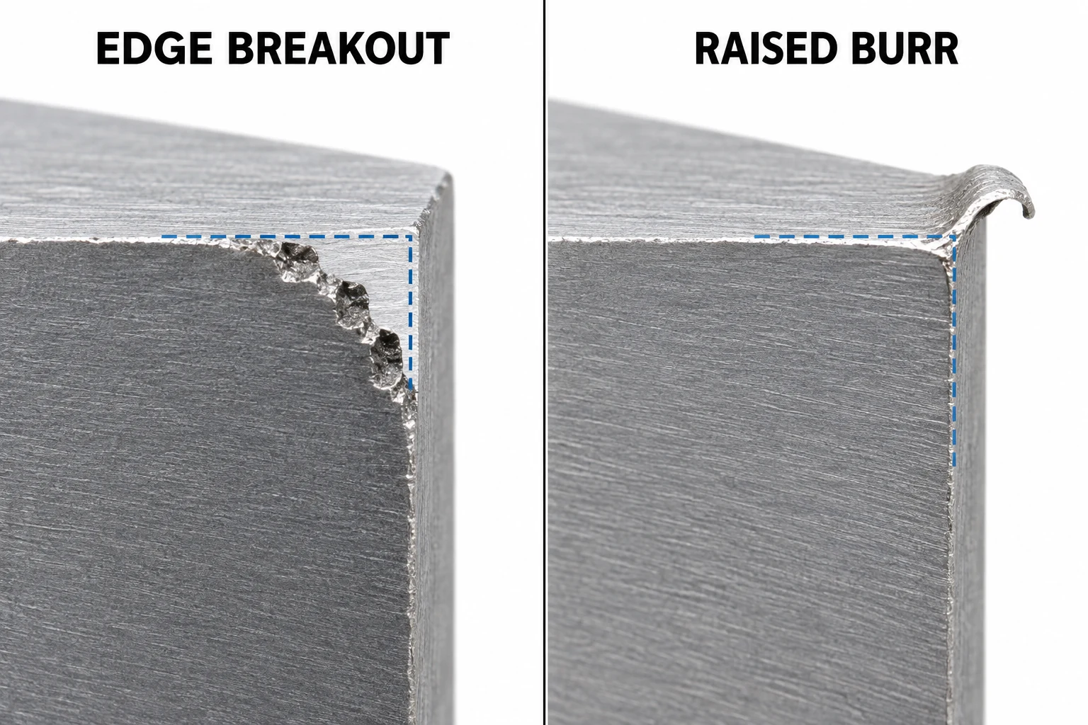
A chipped edge is missing material. A burr is material projecting beyond the intended contour. Removing the burr can restore an edge; removing more material cannot restore a corner that has broken away. Inspect these separately from the texture of the milled face.
| Observation | Useful next check |
|---|---|
| Breakout at the cutter exit | Check edge support, tool wear and the exit cut; preserve any specified sealing edge. |
| Raised lip or smeared material | Inspect the cutting edge for adhered material and review the cutting conditions before deburring. |
| Poor texture across the face | Inspect tool condition and the setup; measure the specified surface requirement rather than judging shine. |
| Correct-looking face, poor assembly fit | Check dimensions and datum relationships independently of surface appearance. |
The table is a checking sequence, not a diagnosis from appearance alone. Gray-iron exit damage and steel burr formation are recognized milling concerns, but a loose setup or damaged tool can also affect the result. [3]
Compare a material change on the finished feature
For a proposed steel-to-iron change, keep the drawing’s functional requirements fixed while comparing candidate processes:
- Identify both materials: grade, supplied condition, hardness information and blank form.
- Select representative features: include a finished face, an exit edge and any fit that controls assembly.
- Record the machining conditions: tool and insert, engagement, speed, feed, holding method and coolant mode.
- Compare useful outcomes: acceptable feature quality, tool condition, cutting time and cleanup effort—not cutting time alone.
A trial that uses different stock allowances or acceptance criteria cannot isolate the material’s effect. For an existing steel design, keep its specified steel grade and treatment as the baseline until an alternative is approved.
Questions about milling cast iron
Can cast iron use the same milling settings as steel?
Sometimes a ductile-iron application has similar tooling requirements to low-alloy steel, but the material name is not enough to transfer settings. Match the grade, matrix, hardness, cutter and cutting conditions before selecting starting data.
Does a better-looking surface mean a more accurate part?
No. Surface texture, size and geometric relationships are separate requirements. A bright face can still have the wrong location or form; a darker face can meet the drawing. Inspect the characteristics that control function.
Sources
- Universidad Complutense de Madrid, Metallographic Atlas: gray iron in a pearlitic matrix; ASTM International, A536, Standard Specification for Ductile Iron Castings, public scope.
- Dura-Bar, Machining Guide, April 2019. Chip examples and cutting-data limits apply to the producer’s specified continuous-cast grades.
- Sandvik Coromant, How to Do Milling in Different Materials, steel, gray iron and nodular iron sections.
- ASTM International, A48/A48M-22, Standard Specification for Gray Iron Castings, public abstract and scope.
- Sandvik Coromant, Dry Milling or with Cutting Fluid.
- Dura-Bar, Top 4 Machining Tips, February 2019; recommendations concern Dura-Bar stock and suitable setups.


