On this page
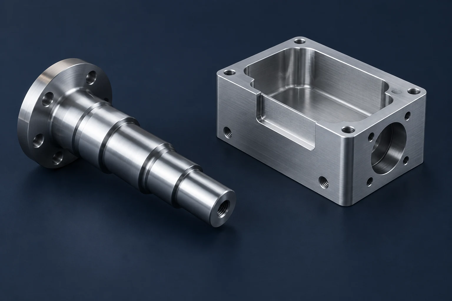
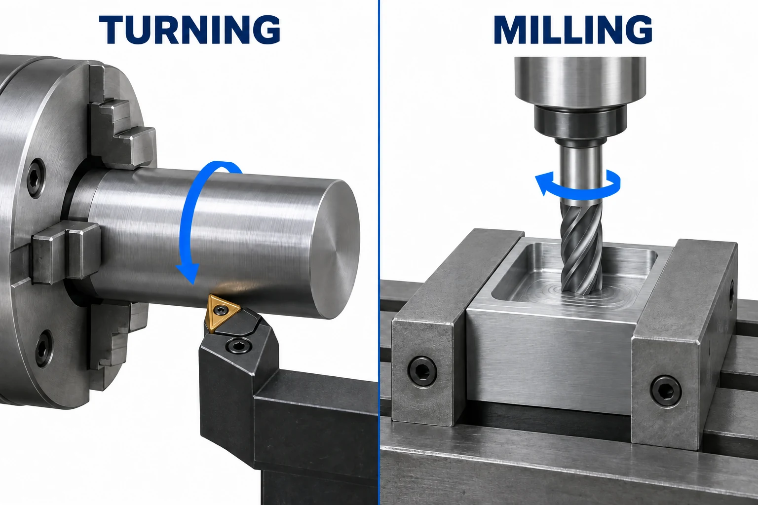
A CNC lathe normally rotates the workpiece against a cutting tool that does not spin. A CNC mill rotates the cutter and moves it relative to a secured workpiece. That difference makes turning a natural starting point for shafts, sleeves and other features arranged around one axis; milling is a natural starting point for pockets, flats and features spread across several faces. A part with both kinds of features may need both processes. [1]
For a machined component, the useful question is which route can produce its important features with stable support, clear tool access and a manageable number of setups. The outside silhouette is only the first clue.
How cutting motion changes the shapes you can make
During ordinary turning, a tool feeds along or across the axis of a rotating part. Feeding along the axis can reduce an outside diameter; feeding across an end produces a face. A boring tool can finish an internal diameter. These operations suit features that share a centerline, including stepped diameters, shoulders and grooves. Our guide to turning operations explains those cuts individually. [2]
In milling, the cutter can follow a path across a face, around a profile or through a pocket. The workpiece stays secured, but it is not necessarily motionless: the table may translate, and a rotary axis may index or turn it. A circular toolpath also lets a mill produce a round opening. “Round feature” therefore does not automatically mean “lathe.” [3] The CNC milling process guide follows these motions through cutter and toolpath choices.
Match the process to the features
Start with the surfaces that control how the component works. A large round outline may be less important than the pockets inside it; a rectangular flange may be secondary to the bore and bearing seats it supports.
| Part requirement | Likely starting route | What could change the route? |
|---|---|---|
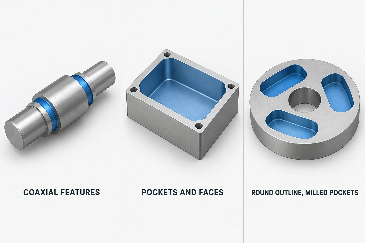
| Stepped shaft with shoulders and circumferential grooves | Turning | Flats, cross holes or keyways add operations; slender sections need suitable support. |
| Sleeve with an axial bore and outside diameter | Turning and internal machining | A thin wall, difficult bore access or a later treatment may change the holding and finishing sequence. |
| Housing with open pockets, mounting faces and separated hole locations | Milling | Deep pockets and obstructed faces may need different tooling, orientation or another process. |
| Circular plate with many pockets and mounting holes | Milling may complete most features | A demanding outside diameter or bore-to-face relationship may justify a turning operation. |
| Flanged shaft with a hole pattern and wrench flats | Turning plus milling | Compare transfer to a mill with a suitably equipped turning center. |
This is a feature-based shortlist, not a fixed routing rule. For example, a small rectangular blank can be held in a suitable lathe fixture, and a mill can contour a cylindrical surface. The question is whether that approach makes sense for the complete component.
When a part needs both turning and milling
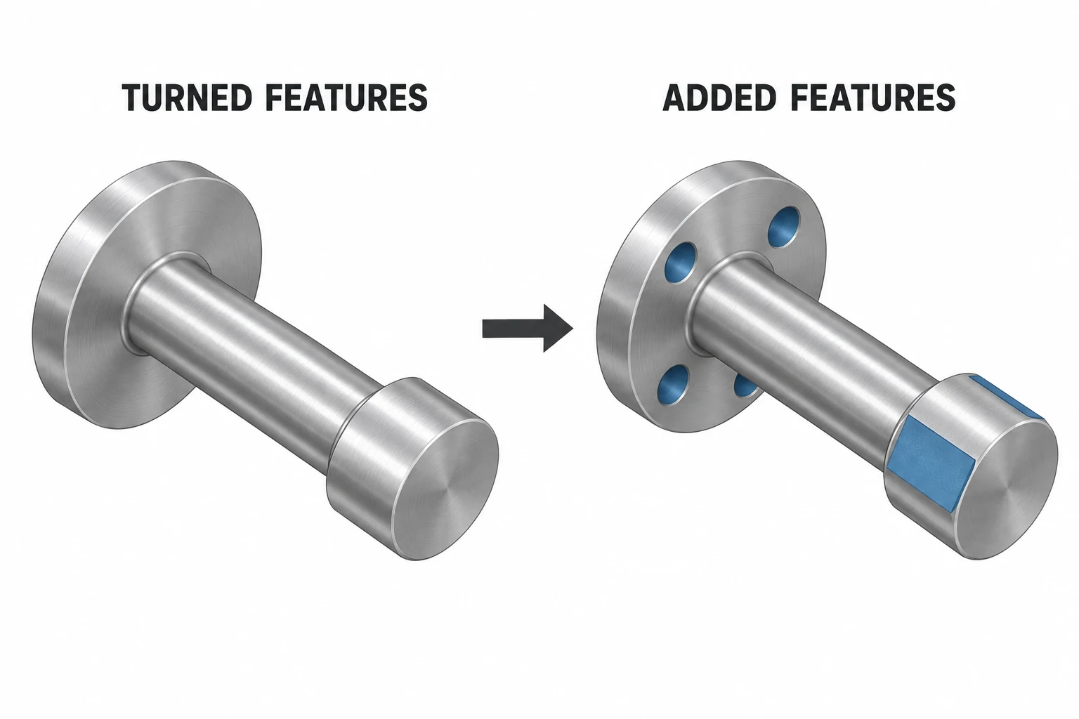
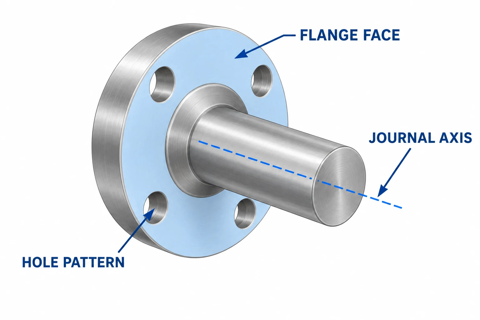
Consider a flanged shaft with a central journal (bearing seat), two wrench flats and bolt holes through the flange. Turning can establish the journal, flange diameter and end faces. The flats and off-center holes require additional operations. On a basic lathe, that usually means moving the part to another setup.
A turning center with driven, or live, tooling can rotate a drill or milling cutter. With the necessary spindle positioning and axis configuration, it can machine selected face or radial features while the part remains held. Haas documents milling, drilling, machining flats and tapping with its live-tooling and C-axis option; the available operations depend on the machine configuration. [4]
Combining operations can remove a transfer and the work of locating the part again. It does not make every mill unnecessary. Tool reach, available axes, fixture clearance, cutting load and the amount of milling still matter. A part dominated by broad pockets may suit a separate mill even if it also needs turning.
Check holding and feature relationships before comparing accuracy
Neither “CNC lathe” nor “CNC mill” establishes the tolerance a finished part will meet. The tool, workholding, material, feature geometry, thermal conditions and inspection method all affect the result. A machine can position accurately while a poorly supported workpiece still moves under cutting load. [3] [5]
On the flanged shaft, ask which relationship matters in the assembly. If the bolt pattern must be located from the journal axis, the milling setup needs a reliable way to establish that axis. If a sealing face must run true to the journal, the process and inspection plan must preserve and verify that relationship. Machining several related features in one holding can reduce relocation errors, but it does not prove the final result without measurement.
Also identify the surfaces used for gripping. A chuck jaw or vise can block a feature that needs machining. Thin walls can distort under clamping force, and a long unsupported section can deflect. A second setup is sometimes the practical way to expose a surface or support it properly, rather than something to eliminate at any cost. [5]
Compare the complete route at the required quantity
A simpler-looking machine route is not always the lower-cost route. Compare the same material and condition, drawing revision, quantity, finish and inspection requirements. Include programming, fixtures, setup, cutting time, transfers and any finishing operations. Our CNC machining cost guide explains how those items enter a quotation.
For a small batch, a familiar lathe-and-mill route may avoid substantial programming or specialized workholding. For repeated orders, an integrated route may recover its preparation cost through shorter handling and cycle time. Those are alternatives to evaluate, not a universal break-even quantity.
A useful comparison lists the proposed setups beside the critical features each setup finishes. If one route is cheaper, check whether it includes the same inspection, deburring, surface treatment and handling of finished surfaces. Otherwise, the prices may describe different deliverables.
A practical sequence for choosing the route
- Identify the dominant features. Separate diameters and axial faces from pockets, flats, slots and off-center holes.
- Mark the functional relationships. Show which bores, journals, faces and hole locations must stay aligned or positioned relative to one another.
- Check access and support. Consider how each operation reaches its feature and where the part can be held.
- Compare complete alternatives. Evaluate turning, milling or a combined route at the actual order quantity, with the same acceptance requirements.
For a component ready for manufacture, our CNC turning and CNC milling pages describe the corresponding services. Keep the drawing focused on the required part and its functional requirements unless a particular manufacturing process is itself necessary.
Questions about CNC lathes and mills
Can a CNC mill make round parts?
Yes. A mill can machine circular pockets, bores and outside profiles using an appropriate toolpath and setup. A part made mainly of coaxial diameters may still be more naturally routed through turning.
Can a CNC lathe cut a flat?
A lathe equipped with suitable live tooling and spindle positioning can mill flats. A basic turning configuration should not be assumed to have that capability; the part may need a separate milling setup.
Should I specify milling or turning on the drawing?
Specify the geometry, material, functional tolerances and surface requirements first. Add a process requirement when it is necessary to the design or approval basis. Otherwise, allow the manufacturer to propose a route that meets the complete requirements.
Technical references
- MIT OpenCourseWare — Lathe and Introduction to the Mill. Cutting motion and typical operations.
- Sandvik Coromant — General turning; External turning. Tool feed and rotational features.
- Sandvik Coromant — What is successful milling? Feature access, component rigidity and process selection.
- Haas Automation — 4000-rpm Live Tooling with C Axis. An example of configuration-dependent secondary machining.
- MIT Center for Bits and Atoms — Subtractive Path Planning. Cutting forces, workholding and machining strategy.


