On this page
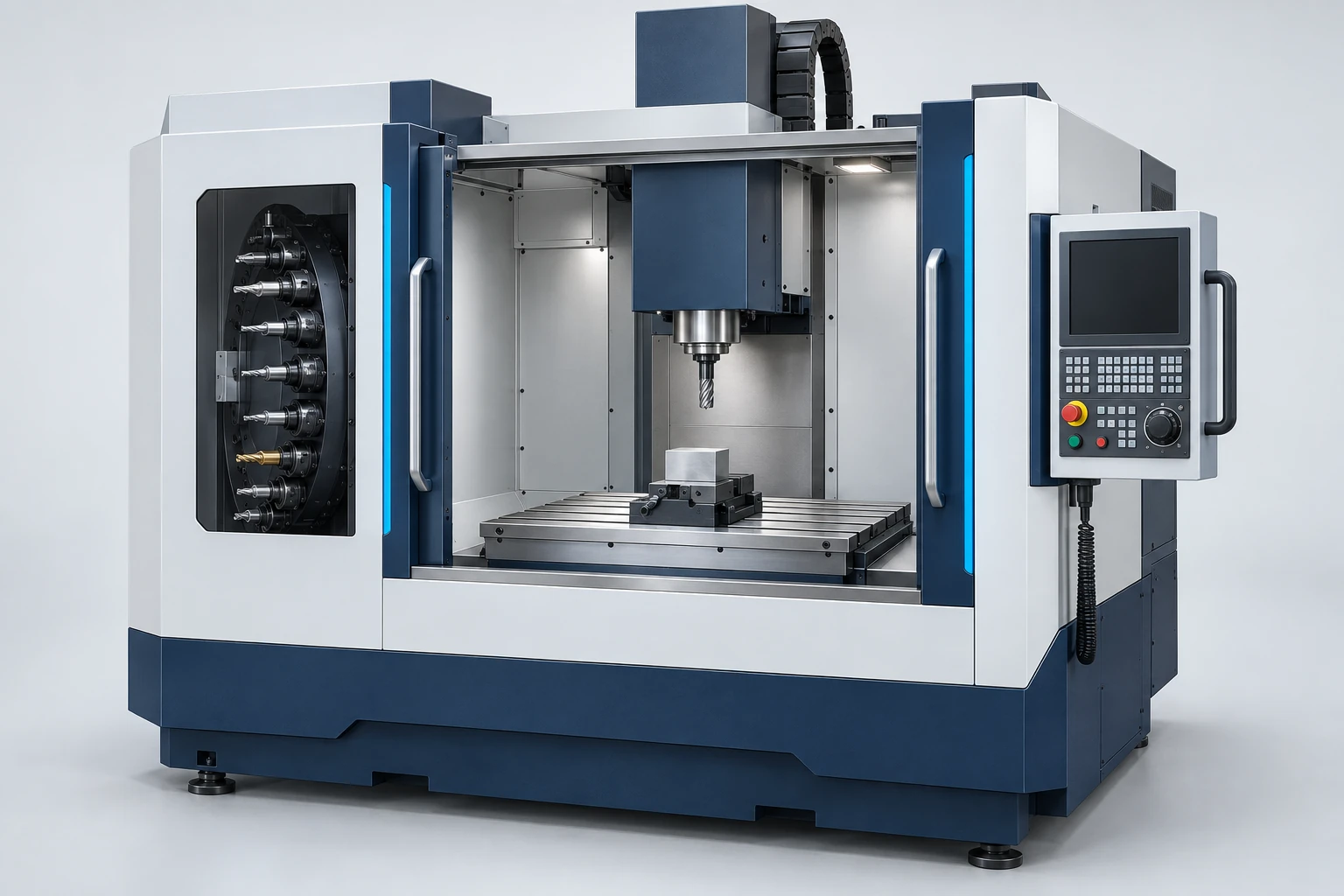
A CNC machining center combines programmed axis motion, a rotating tool spindle and automatic tool changing to carry out operations such as milling, drilling, boring and tapping. Its useful capability comes from the whole configuration: which surfaces it can reach, how the part is held, what the spindle and tooling can cut, and how the result is controlled.
The names on a machine brochure describe different things. “Vertical” identifies a spindle arrangement; “five-axis” describes controlled motion; “gantry” describes a structural layout. A machine can belong to all three categories. Understanding those layers is more useful than treating CNC machine types as a ladder from basic to advanced.
What the main components contribute
Follow the connection from program to cutting edge. The CNC control interprets programmed moves and coordinates the drives; the axis system positions the tool relative to the work. The spindle rotates a tool held in a suitable holder. The table and fixture locate and restrain the workpiece, while the frame and guides support the assemblies under load.
The automatic tool changer (ATC) retrieves different tool assemblies from a magazine. That lets a single setup move from rough milling to drilling and finishing without a manual exchange at every step. The magazine stores tools; the spindle does the cutting. More magazine pockets increase the available tool inventory, not spindle strength.
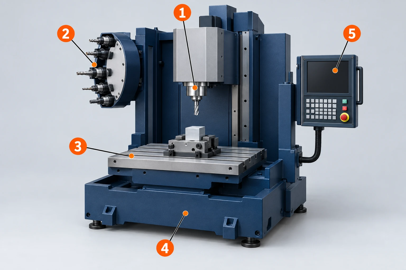
Coolant delivery, chip removal, lubrication and measurement systems support this chain. For example, a capable cutter still needs an escape route for chips, and an accurate program still needs correct work and tool offsets. The Haas mill manual illustrates how these assemblies fit together. For the individual parts and basic motion, see our milling-machine introduction.
Read machine types as overlapping configuration choices
A vertical machining center (VMC) typically approaches the work with an upright spindle. A horizontal machining center (HMC) approaches from the side. A gantry or bridge layout spans the work area with a supported cross-member; which structure moves depends on the design. Some machines combine that layout with a tilting head.
| Configuration layer | Typical descriptions | What it helps you understand |
|---|---|---|
| Spindle arrangement | Vertical, horizontal | The basic direction of tool approach and likely workholding arrangement. |
| Structure and moving assemblies | Column, bridge, gantry; moving table or moving head | How the work area is supported and which masses move. |
| Controlled motion | Three linear axes; additional rotary axes | Which orientations are available and whether they can change during a cut. |
| Tools and part handling | Tool magazine, pallet changer, pallet pool, robot loading | How tools and work enter the process and how much preparation can occur outside cutting time. |
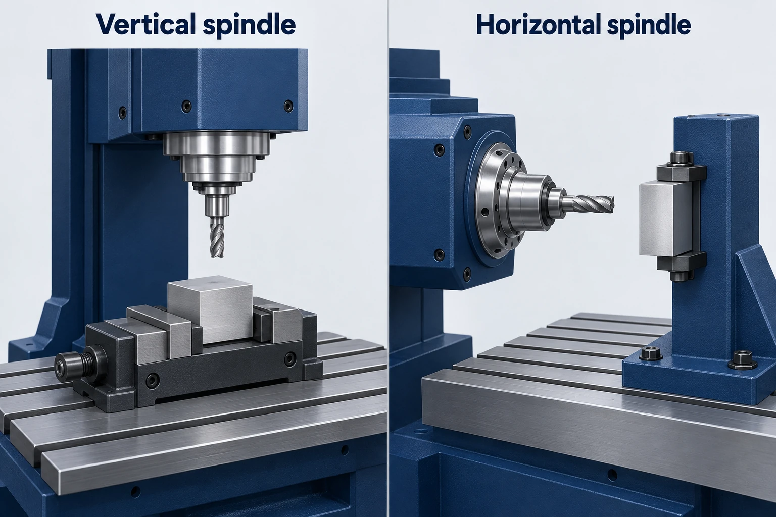
These layers can be combined. A VMC may have a two-axis rotary table and pallet automation; an HMC may use indexing rather than simultaneous multi-axis cutting. A large bridge machine may have a fixed spindle or a swiveling head. Gantry machine configurations demonstrate why the structural name alone does not settle axis capability.
Orientation affects access and chip escape, but pockets and fixtures can still trap chips. Our vertical versus horizontal milling comparison examines those setup trade-offs in detail. Here, the next question is what motion the selected configuration actually supports.
Separate axis count from the way the axes are used
Three linear axes let the cutting edge move through a volume. They can produce many curved surfaces as well as flat faces, provided the fixed tool orientation reaches the geometry. “Three-axis” does not mean “flat parts only.”
An added rotary axis can bring another face toward the spindle. Depending on the machine and control, it may index between cuts or move in coordination during machining. Five-axis milling commonly combines three linear axes with two rotary axes; those rotations may be in the table, the head, or split between them.
In 3+2 positioning, the rotary axes establish an orientation and remain fixed during that cutting segment. In simultaneous five-axis machining, orientation can change along the cutting path. Haas describes both modes on its universal machining centers. An angled drilled hole may only need positioning; a surface that benefits from continually changing tool orientation presents a different task.
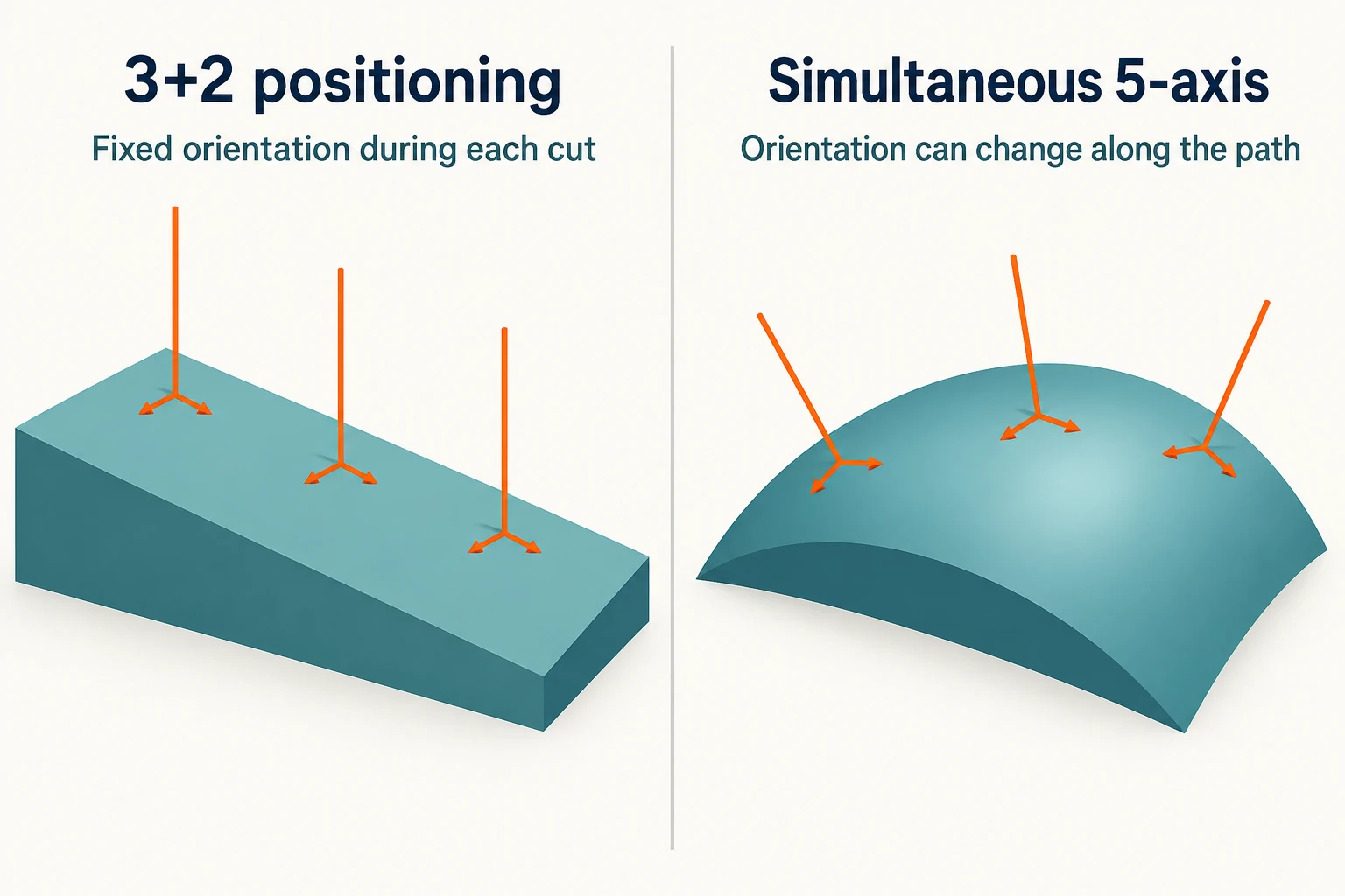
The distinction is the required relative movement, not a claim that every axis must move at every instant. Also check the enabled control functions, rotary travel and interference limits. An installed rotary table does not by itself establish simultaneous capability.
Extra axes can reduce relocations or allow a shorter tool approach, but the held face remains held. A clamp, fixture or spindle housing can still obstruct a surface. Five-axis access is therefore a setup capability, not a promise to finish every surface in one clamping.
Check the space occupied by the complete setup
Axis travel measures movement; table size describes a support surface. Neither is a complete maximum-part specification. Start with the stock and fixture together, then add the holder, cutter, approach moves and any sweep caused by rotation.
Vertical clearance is especially easy to misread. In a simplified vertical setup, the spindle gauge line must sit above the target surface by the tool assembly’s gauge length. Raising the work on a fixture changes that position. A long drill also needs clearance above the work before entering a hole. This is why spindle-to-table distance, tool length and axis travel must be checked together.
For rotary work, a corner that clears the enclosure when upright may swing outward when tilted. The useful space can shrink further once the spindle head and toolholder are included. Haas’s five-axis setup guidance specifically calls for clearance when indexing; a simple bounding box around the bare part cannot establish it.
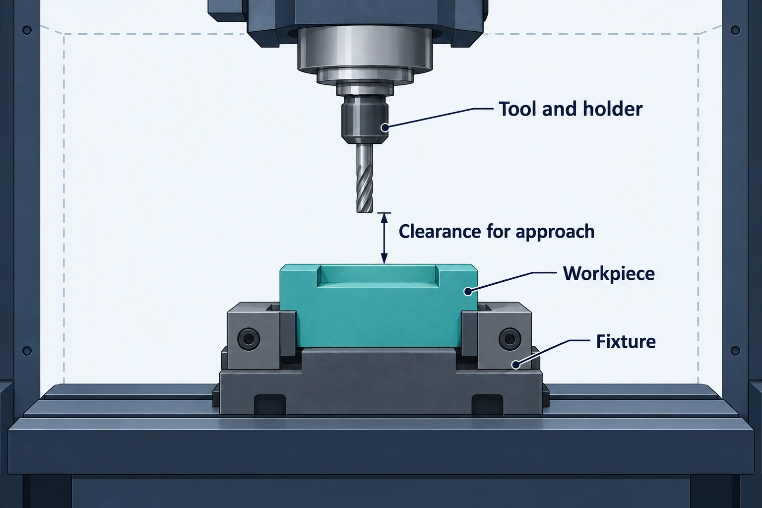
Table or pallet load limits need the fixture and all supported work included. Rotary systems may also impose restrictions on load distribution or overturning moment. A part fitting within the linear travels does not resolve those separate limits.
A useful setup review therefore answers three questions: can the assembly be supported, can every required tool position be reached, and can the entire approach and reorientation path clear surrounding hardware? For close spaces, use the actual machine, fixture and holder geometry in the review.
Match the spindle and tool package to the cut
Maximum spindle speed is only one piece of the cutting system. A small cutter and a large face mill operate at different rotational speeds for the same peripheral cutting speed. Their load requirements also depend on material, engagement and the intended removal rate.
Compare the spindle’s torque and power across the relevant speed range, rather than comparing maximum rpm or peak horsepower alone. Continuous and short-duration ratings are different. A brochure’s highest power value may not be available at the speed required for a particular operation.
The holder, tool interface and overhang matter alongside the spindle. A narrow opening might admit the cutter but block its wider holder. Extending the cutter can improve reach while reducing assembly stiffness. Sandvik’s vibration guidance treats the tool, holder, machine, workpiece and fixture as parts of the same stability problem. That creates a trade-off between clearance, vibration and permissible cutting conditions; a larger machine does not automatically remove it.
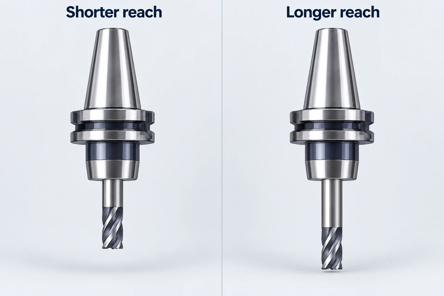
Tool storage has its own limits. Check tool length, diameter and mass, including how oversized tools affect neighboring pockets. A nominal magazine capacity does not mean every pocket can contain the largest allowable tool at once. Tools needed for probing, finishing or replacement also occupy capacity.
Finally, match coolant and chip handling to the operation. Through-tool coolant, where supported by both machine and tool, is one option; it is not implied by the presence of an enclosure coolant hose. A long unattended cycle also needs a credible plan for chips and worn or broken tools.
Distinguish machining capability from production capacity
A pallet changer moves a prepared fixture and workpiece into the machine. A pallet pool holds more prepared jobs. A robot may load individual blanks or finished parts. These systems change handling and scheduling, while the machine’s spindle, axes and workholding still determine the feasible cut.
With a suitable two-station arrangement, one pallet can be prepared outside while the machine works on another. The benefit depends on how preparation time, cutting time and exchange time overlap. If the external task takes longer than the cycle, the spindle may still wait. If cutting dominates, faster loading may change output less than expected.
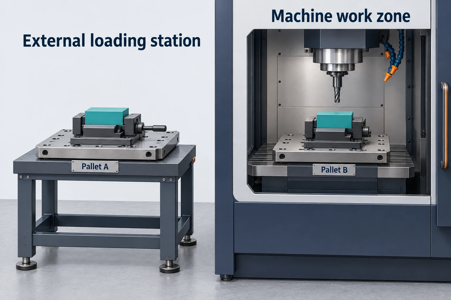
Mazak’s machining-center automation range includes different work and pallet transport systems. The useful distinction is what each system handles, not a universal batch-size threshold. Repeat work may justify reusable fixtures and prepared tool sets; varied short runs may benefit from flexibility instead.
Automation also exposes process dependencies. The next pallet needs the correct program, offsets and tools; the job needs chip capacity, tool-life planning and suitable checks. Adding a pallet pool does not resolve an unstable cutting process or a fixture that distorts the part.
Keep machine motion and finished-part accuracy separate
Positioning accuracy concerns how closely an axis reaches a specified position under stated test conditions. Repeatability concerns the spread when returning to a position. A motion can repeat consistently while still being offset from the desired location. Mazak’s HCN NEO specifications, for example, separate these measures and state the machine and temperature conditions for their sample results.
A finished feature includes more influences: machine geometry and thermal behavior, cutting forces, tool wear, fixture alignment and workpiece movement. A repeatability figure cannot simply be copied into a part’s tolerance. Nor does a fine controller display increment prove equivalent manufacturing accuracy.
Probing supports workpiece setup and selected feature checks; appropriate tool-setting systems can check tools as well. It still operates within a measurement system: machine errors, probe calibration, temperature and sampling affect the result. Decide how each critical feature will be verified, including its condition after release from the fixture or after later processing. On-machine data may support acceptance where the method is suitable and validated; it does not automatically replace every final inspection.
A practical configuration review for one housing
Consider an illustrative housing with a top pocket, side ports, an angled hole and a bottom locating face. The purpose is to identify configuration needs before assigning a machine—not to prescribe a finished process plan.
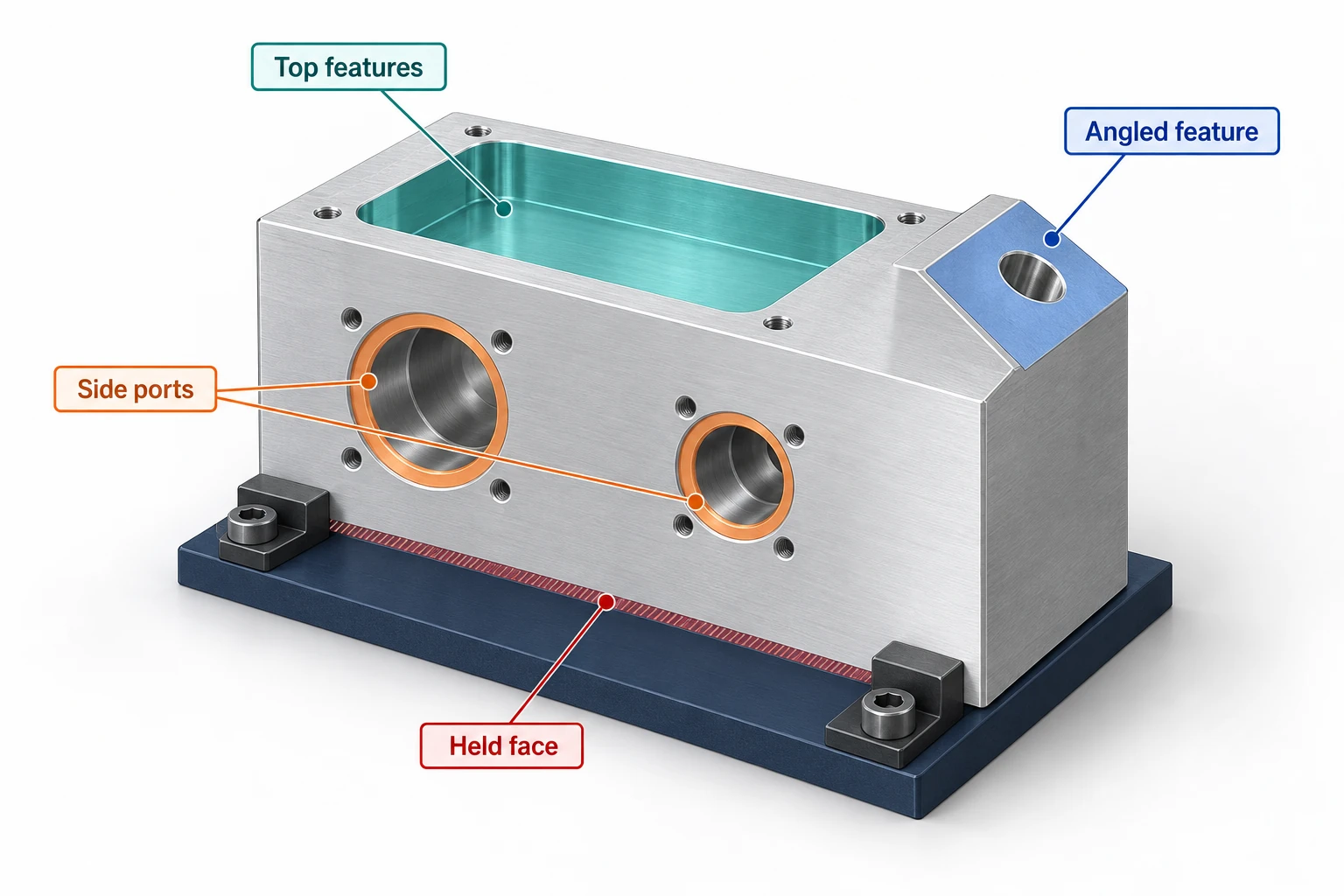
| Requirement | Configuration to investigate | What can still prevent it from working |
|---|---|---|
| Top pocket and mounting features | Fixed-orientation milling with suitable tools and support. | Deep walls, holder interference or inadequate support. |
| Side ports | Additional setups, an indexable HMC, or a rotary-equipped VMC. | Clamps hiding the ports; uncertainty in feature relationships after relocation. |
| Hole on an inclined pad | A dedicated angled fixture or positional rotary access. | Insufficient approach clearance or rotary travel; simultaneous motion is not required merely because the hole is angled. |
| Bottom locating face | A holding strategy that leaves it accessible, or a later setup. | The face used to hold the first setup cannot be cut through its fixture. |
| Repeated batches | Reusable fixtures, adequate tool inventory and suitable loading automation. | Preparation bottlenecks, tool-life limits or poor chip control. |
| Closely related critical features | A controlled datum strategy and an appropriate measurement plan. | Thermal, cutting or clamping effects not captured by machine positioning specifications. |
This review produces a useful configuration brief: necessary access, usable space, cutting demands, handling needs and verification method. More than one machine arrangement may satisfy it. The choice then depends on the complete route, available tooling and order quantity. If those access questions point toward rotary machining, our five-axis machining service page connects the configuration discussion to a specific part review.
Questions about CNC machining centers
Is a CNC machining center the same as a CNC mill?
The terms overlap. A machining center usually combines CNC milling capability with automatic tool changing so it can run several operations in a setup. “CNC mill” is broader; the name alone does not establish tool-changing, rotary-axis or pallet features.
Are vertical, horizontal and five-axis machining centers separate types?
They describe different configuration layers. Vertical and horizontal refer to the basic spindle arrangement; five-axis describes controlled motion. A vertical machine can have five-axis capability, and a horizontal machine can have additional rotary axes. Check the actual arrangement and enabled functions.
Does five-axis machining always mean simultaneous cutting?
No. In 3+2 positioning, two rotary axes establish an orientation before a cutting segment and remain fixed during it. Simultaneous five-axis machining allows orientation to change along the path. The required movement, machine configuration and control determine which mode is available and useful.
Can a machining center also turn parts?
Only when equipped for that function. Circular interpolation with a rotating milling cutter is still milling. Turning on a machining-center platform requires tooling, control and a machine configuration intended for the turning process; an indexing table alone does not establish that capability.
Which specification determines the largest part a machine can make?
No single number does. Evaluate the stock, fixture, load, tool and holder, linear and rotary travel, approach paths and collision clearance together. A part can fit on the table yet leave a feature unreachable, particularly when the fixture adds height or the setup rotates.


