On this page
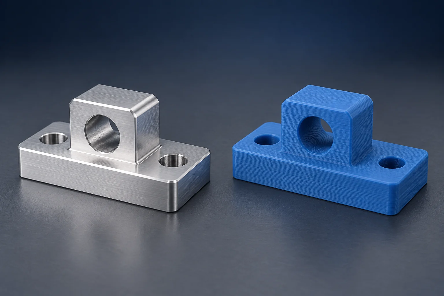
Choose CNC machining when a prototype needs a specified stock material and machined interfaces. Consider 3D printing when complex geometry or frequent shape changes make cutting the part awkward, provided the selected printing process and material can meet the test requirements. A printed body with machined mating surfaces can also be a practical option.
The useful comparison is between finished parts that meet the same requirements. A low-cost plastic print and an aluminum machined part may answer different questions, even when they share a CAD model.
CNC machining and 3D printing: the practical differences
CNC machining removes material with cutting tools. 3D printing builds a part in layers. Here, “CNC” means subtractive machining, such as milling and turning; this is a part-making comparison, not a machine-buying guide. The CNC milling guide explains the cutting process.
| Requirement | CNC route | Printing route |
|---|---|---|
| Specified material | Start with the required stock grade and condition. | Check the actual feedstock, process and finished condition. |
| Complex internal shape | Needs tool access, another process or a split design. | May suit a single build; check supports and internal cleaning. |
| Critical mating surfaces | Plan machining and inspection around those features. | Verify as-printed results or include secondary machining. |
| Several design revisions | Reassess programming, holding and stock for each change. | Reassess orientation, supports and finishing for each change. |
“3D printing” is not one material or accuracy class. Filament extrusion (FFF/FDM), resin printing (SLA), polymer powder-bed printing (SLS) and metal powder-bed fusion produce different structures and need different finishing. Name the intended process when comparing a quotation or test sample. [1]
Material behavior comes before the process label
If a drawing requires a particular aluminum alloy and temper, a polymer print is not an equivalent specimen for stiffness or heat response. It may still be useful for checking installation space. Likewise, two materials called “nylon” need not share the same formulation, conditioning or behavior.
For printed polymers, layer bonding, voids and deposition direction can affect the response to load. NIST’s polymer review explains why material and build conditions belong in the mechanical-property assessment. A solid-fill setting alone does not establish equivalence to machined stock. [1]
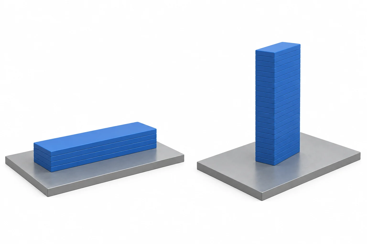
Metal printing also needs a process-specific assessment. NIST’s review of laser powder-bed fusion identifies microstructure and defects among the causes of directional tensile properties. That does not establish that every printed metal is weaker than every wrought alloy. [2]
Compare applicable material data in the required condition, including the property that matters: stiffness, strength, temperature response or wear. Our materials and part-design guide covers grade, stock form and condition in a part specification.
Separate complex geometry from critical interfaces
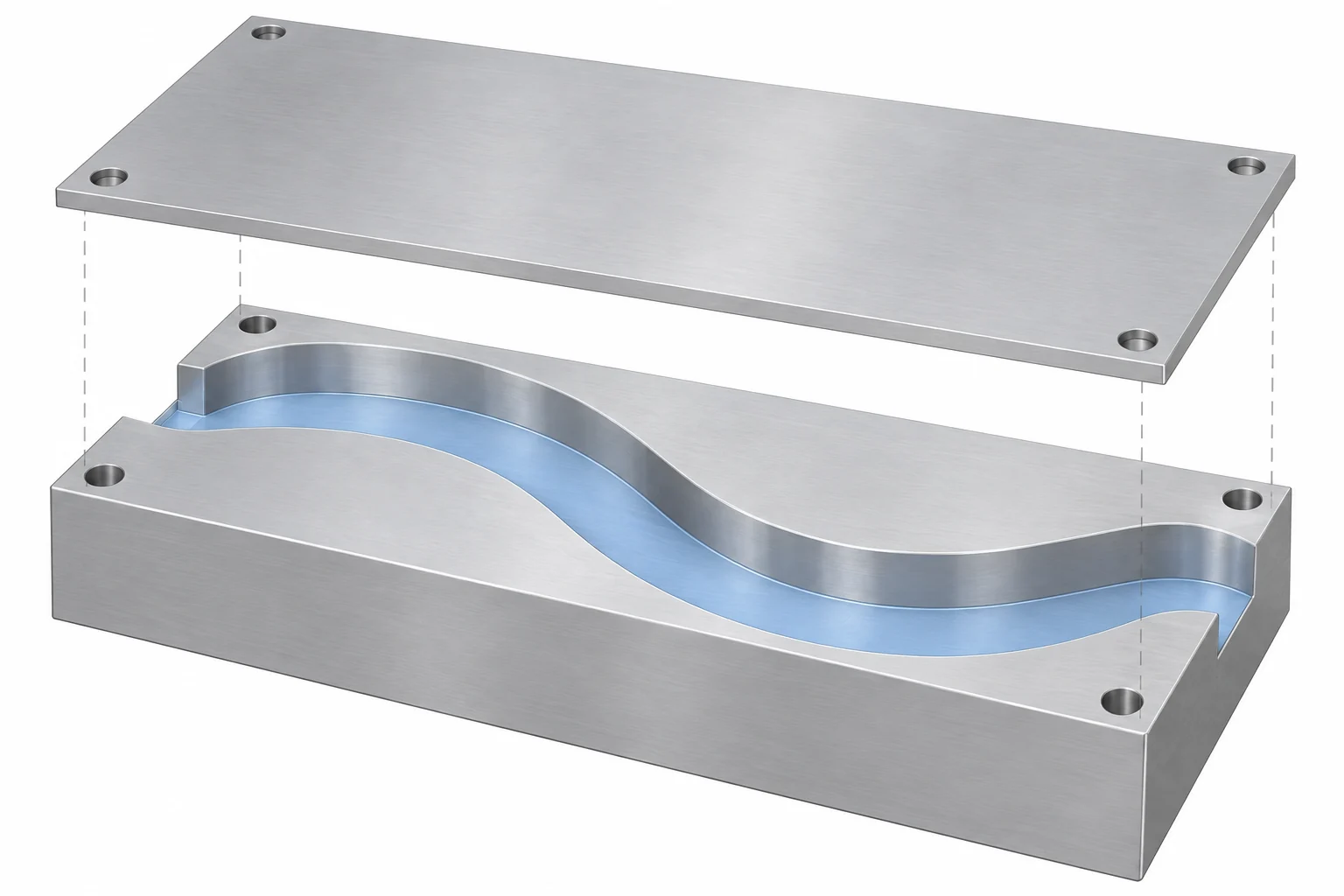
A cutter must reach the surface and clear nearby walls while the workpiece remains supported. Printing can create shapes that are difficult to cut from one blank, but enclosed geometry still needs a workable cleanup route. Formlabs’ Fuse 1 guidance, for example, requires provision for removing loose powder from cavities. Its specific hole recommendations apply to that system, not every printer. [3]
Do not compare a printer’s layer height with a drawing tolerance. Layer height describes a build setting, not the permitted error in a finished bore or distance between holes. Geometry, material and post-processing affect the actual dimensions. Surface texture and dimensional accuracy are also separate requirements. [4]
For a locating bore, mounting face or threaded interface, compare the final inspected feature. Printing the body and then machining selected surfaces can combine geometric freedom with controlled interfaces; NIST discusses drilling, tapping and surface finishing of additive parts for assembly requirements. [5] Plan the machining allowance, locating surfaces, tool access and holding before printing. Secondary machining is not automatically feasible on a thin or inaccessible feature.
Applying the choice to a sensor mount
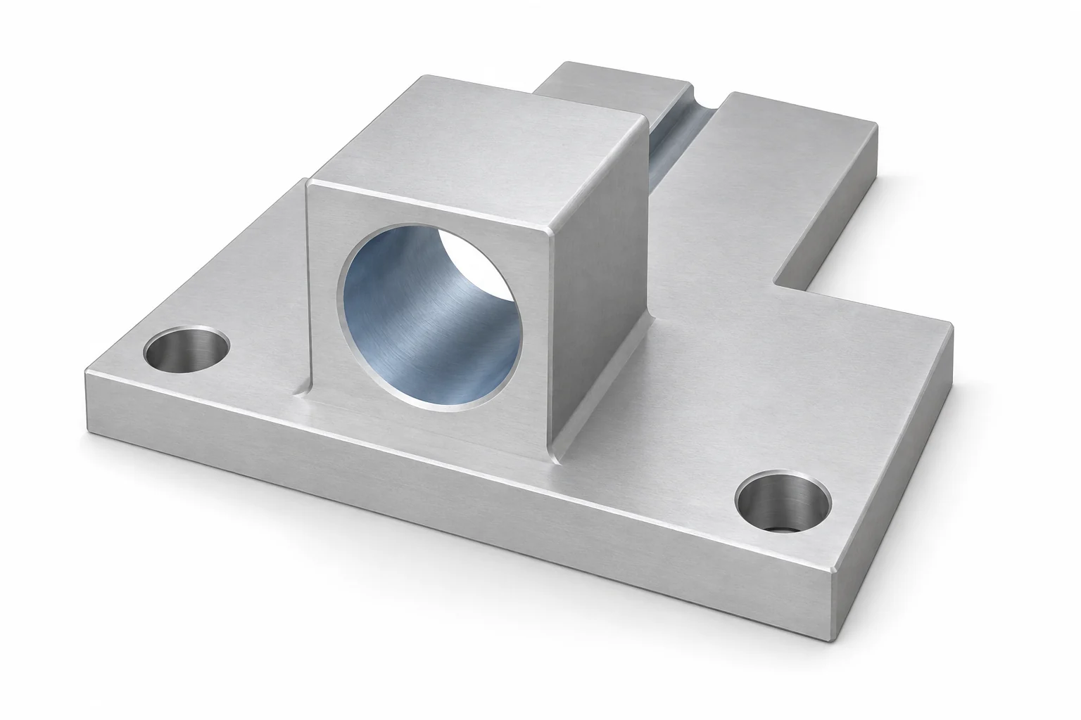
Consider a small sensor support with two mounting holes, a locating bore and a cable passage. For an installation check, a polymer print can be a candidate if its dimensions and rigidity are adequate for that check. If the mount must represent a specified metal design under load, the material and condition become part of the selection.
Review the features separately:
- Mounting face and holes: keep the required seating and location relationships in either route. A visually similar outline does not establish alignment.
- Locating bore: determine whether the finished printed feature meets the fit. If machining is needed, provide enough material and a usable reference for locating the bore.
- Cable passage: an open groove may be straightforward to machine. A curved enclosed passage may favor printing, but only if it can be cleaned and inspected as required. A separate cover is another design option.
If both routes satisfy these requirements, cost and availability can decide. If neither does, revise the design or process plan before ordering. Changing the passage or adding a joint needs design approval; it is not merely a supplier’s pricing adjustment.
Compare the complete delivered prototype
Neither cutting time nor print time gives the full schedule. Stratasys’ comparison separates preparation, manufacturing and finishing, and cautions against a universal speed ranking. [6] Compare the following scope for the same revision and required quantity:
| Include in the comparison | What to clarify |
|---|---|
| Preparation | Programming, build preparation, fixtures and stock or feedstock availability |
| Finished condition | Deburring, support or powder removal, applicable curing/heat treatment, machining and finish |
| Acceptance | Critical dimensions, inspection records and any agreed rework |
| Arrival and revision | Queue, delivery, and the cost of changing the next build |
Quantity changes the comparison: setup can be spread over repeated machined parts, while printing may allow parts to share a build. Neither creates a universal break-even quantity. Obtain prices at the quantities you actually need, and keep optional cosmetic finishing separate from work required for the test.
For the machining route, our CNC prototyping and production service explains sample and repeat-order planning. A useful process decision identifies the selected material, finished interfaces and order scope, rather than simply marking one technology “better.”
Questions about CNC and printed prototypes
Can a 3D-printed part be a functional prototype?
Yes, when its material, geometry, finished condition and build orientation are suitable for the function being evaluated. “Printed” does not mean appearance-only, and “machined” does not mean every function has been validated.
Is CNC machining always more accurate?
No single ranking covers every process and feature. Compare achievable finished dimensions and surface requirements for the particular part. Printer resolution and machine positioning specifications alone do not establish finished-part accuracy.
Sources
- NISTIR 8059, Materials Testing Standards for Additive Manufacturing of Polymer Materials, 2015, material structure and build conditions.
- NIST, Understanding Anisotropic Tensile Properties of Laser Powder Bed Fusion Additive Metals, 2021, abstract and stated scope.
- Formlabs, Design specifications for 3D models (Fuse 1 generation), holes, internal powder removal and system-specific design guidance.
- Formlabs, Guide to 3D Printing Tolerances, Accuracy, and Precision, resolution, materials and post-processing.
- NIST, Post-process machining of additive manufactured stainless steel, 2015, abstract on finished assembly features.
- Stratasys, 3D Printing vs. CNC Machining, 2021 white paper, preparation and manufacturing workflow. Its example rates are not used here.


