Skip to content
VETCNCCNC MANUFACTURING
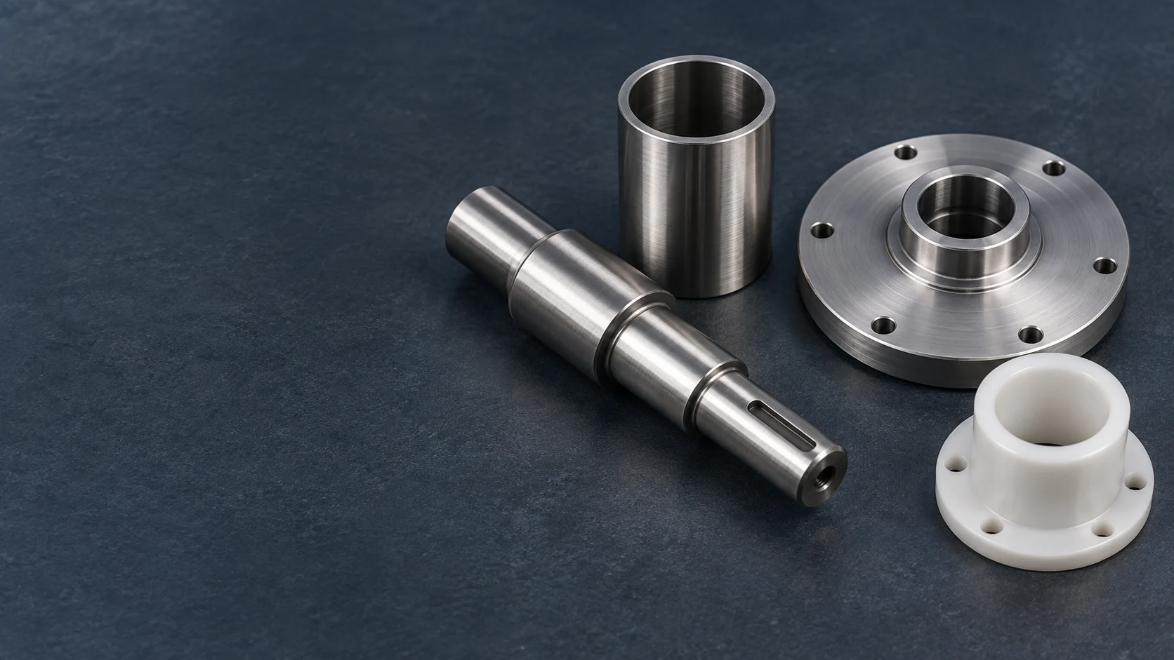
Stepped shaft, hollow sleeve, circular mounting cover and white flanged bushing on a dark surface

Marine CNC Machining

We machine auxiliary pump shafts, sleeves, housings and equipment mounts for marine equipment manufacturers. We work from your component drawings and specified materials, keeping shaft fits, sealing tracks and exposed mounting joints distinct through machining and inspection.

  • Auxiliary pump parts
  • Equipment mounting parts
  • Drawing-defined interfaces

Machined parts for marine auxiliary equipment

Our component scope covers rotating interfaces, empty housings and mechanical equipment mounts. Parts follow the equipment design, including which surfaces contact the working fluid and which see only atmospheric or splash exposure.

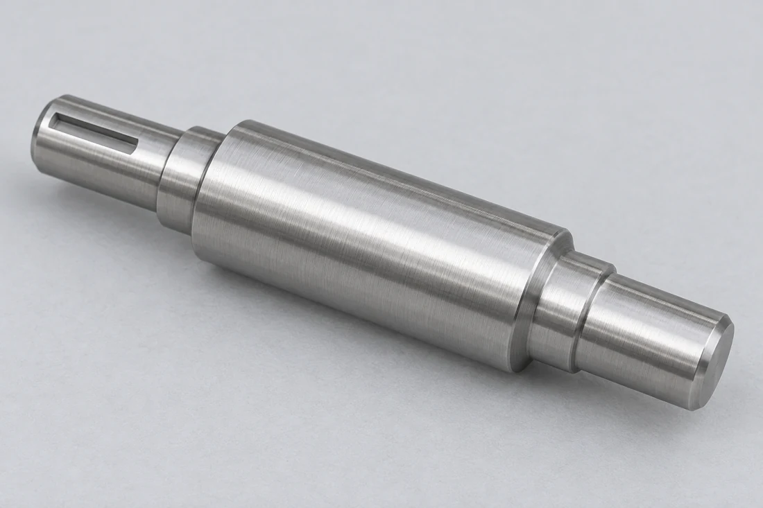
Short stepped metal shaft with smooth cylindrical seats and a keyway at one end

Auxiliary pump shafts

We turn stepped shafts with the specified bearing seats, sleeve locations and drive features. The drawing separates each working diameter from the seal track and defines their relationship to the shaft axis.

  • Bearing seats
  • Sleeve locations
  • Drive features
Discuss this component
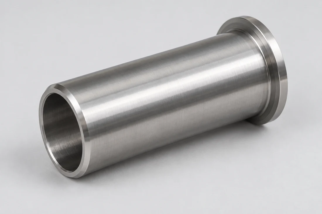
Hollow cylindrical shaft sleeve with an end flange and chamfered opening

Replaceable shaft sleeves

Sleeves provide the defined surface between a shaft and its selected seal or adjoining component. The shaft fit, outside working diameter and axial retention are specified together.

  • Shaft fits
  • Working diameters
  • Axial retention
Discuss this component
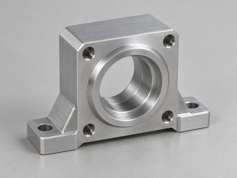
Metal bearing-support housing with a stepped central bore and two mounting feet

Pump covers and bearing housings

We machine empty housings and covers with bearing bores, register diameters and closure faces. Connected features follow the pump designer’s datums; a cover’s outside shape alone does not define its fit.

  • Bearing bores
  • Register diameters
  • Closure faces
Discuss this component
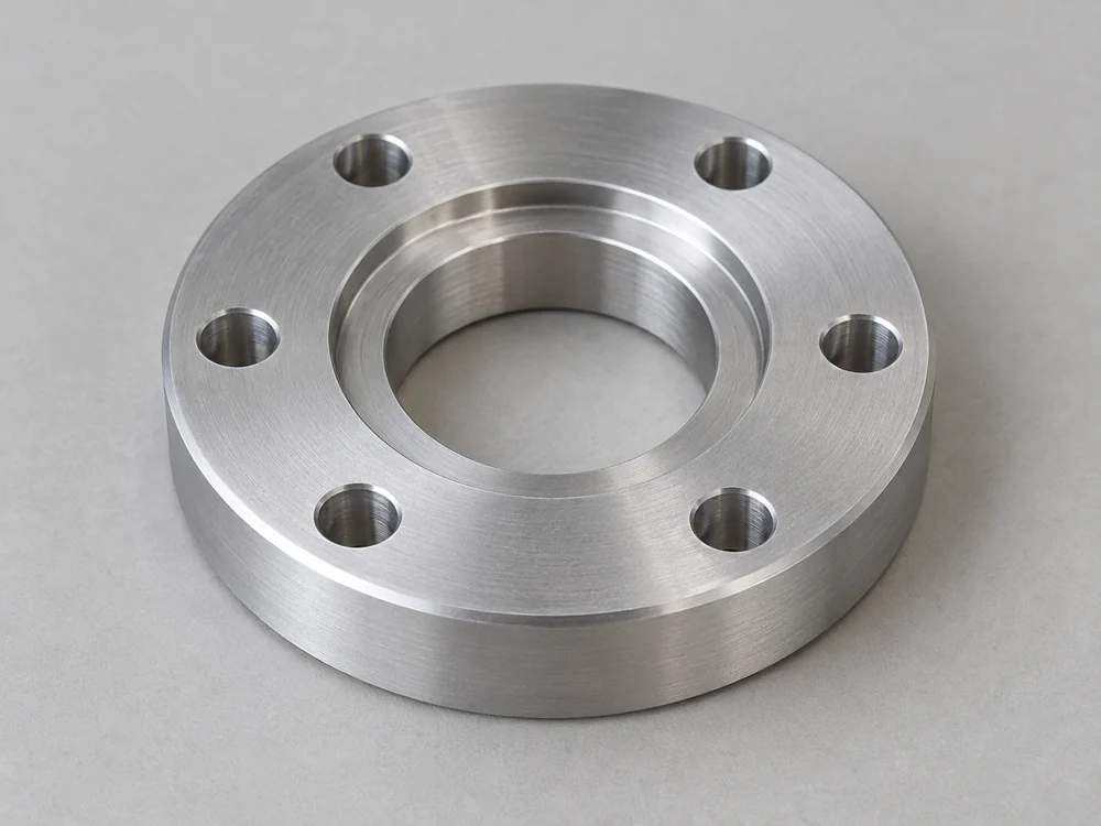
Circular mounting flange with six fixing holes and a concentric locating step

Equipment flanges and adapters

Mounting adapters join equipment interfaces with separate bolt patterns or locating pilots. We machine the defined register and face relationship without treating a mounting flange as a rated pipe connection.

  • Locating pilots
  • Bolt patterns
  • Face relationships
Discuss this component
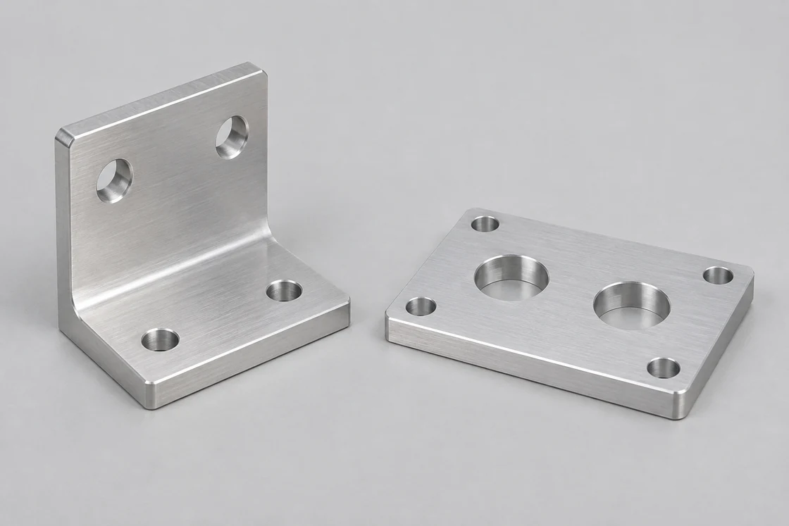
Metal L-shaped mounting bracket beside a flat mounting plate

Deck-equipment mounting brackets

Brackets and support plates locate auxiliary equipment on its installation base. The design includes the selected fastener arrangement and any isolation pieces between dissimilar metals.

  • Equipment patterns
  • Mounting faces
  • Isolation allowances
Discuss this component
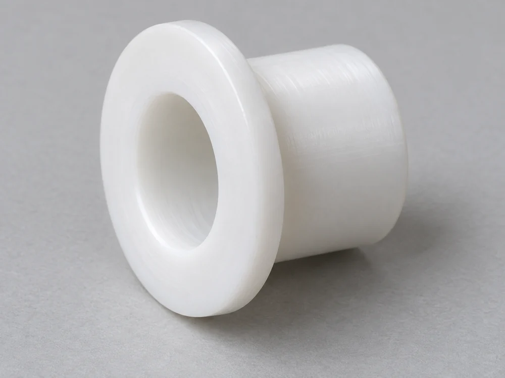
White flanged polymer guide bushing with an open central bore

Polymer guide bushings and spacers

We machine specified polymer guide bushings and spacing details for supported moving parts. Their finished bore and seating length follow the installed arrangement and the selected stock grade.

  • Guide bores
  • Seating lengths
  • Named stock grades
Discuss this component

Pump interfaces, exposed mounts and onboard supports

Marine equipment combines different exposure conditions and assembly requirements. We keep the fluid-contact boundary, exposed mounting joint and service-access envelope visible in the component definition.

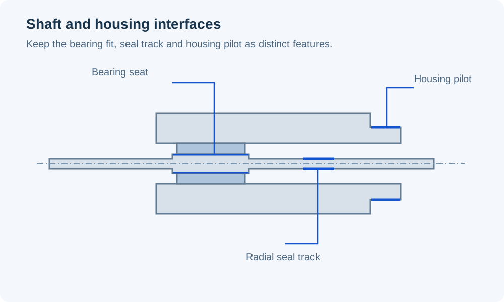
Section through an auxiliary-equipment shaft and housing, separating the bearing seat on the shaft, radial seal track and external housing pilot

Keeping shaft location separate from sealing

A bearing seat locates the shaft, while a radial seal runs on its own counterface. We machine the specified diameters and relate them to the common reference axis; a bearing-fit tolerance is not automatically the correct seal-track tolerance.

The cover pilot and seating face establish the housing relationship. Runout and face requirements refer to the assembly’s chosen datums, rather than to a convenient outside surface of the casting or blank.

Selected seal arrangement

The component drawing identifies a radial lip-seal track or another seal interface. Its finish requirements follow that selected arrangement.

Housing location

The pilot, bore and closure face are measured as related features so the cover seats in the intended position.

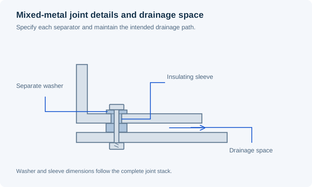
Section of a bracket and base joint with a separate insulating washer and sleeve around the fastener, plus open drainage space between the mounting surfaces

Mounting equipment where saltwater can reach the joint

We machine the mounting stack shown in the assembly: bracket, base interface and any separate sleeve or washer seats. Nickel Institute guidance identifies metal pairing, electrical contact, electrolyte and exposed area ratio as relevant to galvanic corrosion.

An insulating washer does not isolate a joint if the bolt shank or another metal path still connects it. The approved assembly defines where separation is required; the machined part provides the specified clearance and seating geometry.

Material pairing

The part material is considered with the adjoining base and fasteners, not as an isolated alloy choice.

Complete joint geometry

Sleeve length, washer seating and fastener clearance must agree with the actual mounting stack.

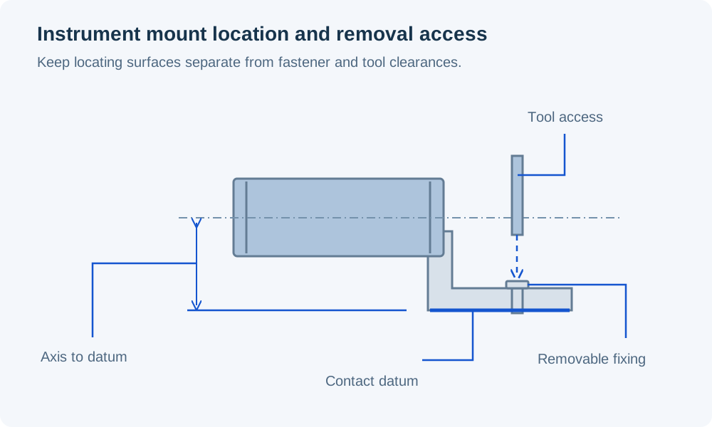
Mechanical instrument envelope on a mounting bracket, showing its axis relative to the contact datum and clear vertical tool access to a removable fixing screw

Supporting instruments while retaining maintenance access

We machine mounting faces and locating features for onboard instrument and auxiliary-equipment supports. The reference face establishes the installed direction; the surrounding envelope leaves access to connections and removable fasteners.

A support must also allow the equipment to leave the installed position. The removal path can require more space than the component occupies during operation.

Installed alignment

The locating face and device pattern define the required mechanical orientation on the equipment base.

Service envelope

Tool access and the withdrawal direction remain clear of the adjacent cover, guard and installed pipework.

Fit trials, equipment evaluation and repeat parts

Each delivery is tied to a specific component revision and its intended use in the equipment program.

Interface-fit parts

Initial shafts, sleeves or adapters establish seating, installation access and the relationship to retained equipment interfaces.

Equipment evaluation parts

The selected material and final surface condition are used for the equipment team’s application evaluation. Modified fits or coating boundaries remain identified when a trial leads to a revision.

Released parts and spares

Repeat parts retain the approved grade, fits and finish requirements. Spare-part identity includes the equipment configuration where otherwise similar components have different working interfaces.

Material references for marine equipment parts

Atmospheric exposure, intermittent splash and continuous immersion are different selection conditions. Temperature, crevices and adjoining metals can change the result. PRE compares stainless compositions for pitting resistance; it is not a seawater service-life rating.

Marine CNC Machining — material parameters
Material / conditionReference parametersComponent context
6061-T6 / T6511 extrusionYield ≥240 MPa; density ≈2.71 g/cm³Specified lightweight equipment mounts
316L / EN 1.4404 · Supra 316L/4404PRE 24; CLTE 16 µm/(m·K)Stainless bodies and mating components selected for the exposure
Duplex 2205 / EN 1.4462 · Forta DX 2205PRE 35; CLTE 13 µm/(m·K)Drawing-specified chloride-exposure alternative to assess
Unfilled POM-C · TECAFORM AH naturalTensile modulus 2.8 GPa; water uptake 0.05%Guide bushings and spacing parts

Hydro 6061 extrusion: minimum yield and typical density. Outokumpu: PRE is a dimensionless comparison based on typical composition; stainless CLTE is for 20–100°C. Ensinger POM-C: typical modulus at 1 mm/min; water uptake after 24 h at 23°C. CLTE means linear thermal expansion. These references do not approve a grade for a particular seawater duty.

Machining shafts, housings and equipment interfaces

The operation sequence preserves the working references through roughing, finishing and any change of setup.

Shaft fits, seal tracks and mounted joints

We identify the surfaces that locate, seal and clamp before assigning their individual dimensional and finish requirements.

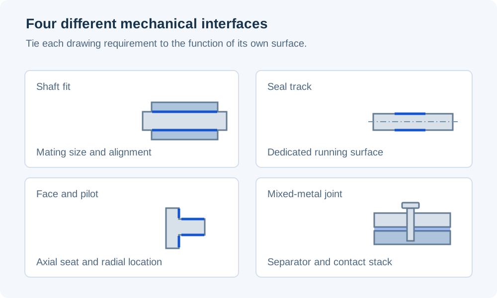
Four mechanical details distinguish a shaft fit, a separate smooth seal track, a mounting face with pilot and a mixed-metal fastened joint

Shaft and sleeve seating

The working diameter and axial shoulder control how the sleeve or bearing is positioned. Corner relief must let the mating component contact the intended shoulder.

Radial seal counterface

Where a radial lip seal is specified, the track needs its own roughness, form and surface-condition requirements. A general polished-finish note does not define that contact.

Housing pilots and closure faces

Pilot fit locates the cover radially; the seating face establishes its axial relationship. Surface texture and any gasket or seal groove follow the chosen closure design.

Dissimilar-metal mounting stack

The isolation detail, if specified, includes the bolt passage as well as the faces between the bracket and base. Required drainage or access features must be part of the released geometry.

Surface treatment and protected working areas

We separate the exterior treatment from the dimensions and surface condition needed at fitted or sealing interfaces.

Stainless surface treatment

The order identifies the required cleaning or passivation process and acceptance documentation. Seal tracks, threaded fits and gasket contacts retain their own finished-condition requirements.

Coated aluminum mounts

The coating plan identifies covered and masked areas, including fitted bores and mating faces. Where coating affects fit, acceptance dimensions apply after the specified treatment.

Edges and inaccessible pockets

We use the drawing’s edge treatment at handled surfaces and assembly entries. Internal corners, passages and recesses receive defined burr and residue requirements before delivery.

Shaft, seal and mounting-interface checks

These conditional references distinguish different features on a marine equipment component. The released drawing and selected bearing or seal determine which limits apply.

We relate measured sizes, runout and face locations to the stated datums. The part record identifies the material condition and any finishing operation that affects the inspected surface.

Marine CNC Machining — feature specifications
Working featureConditional referenceComponent acceptance
Shaft or sleeve locating seath6 at nominal >18–30 mm: −0.013 / 0 mmSize from the selected fit; form and runout separately specified
Housing or cover locating boreH7 at nominal >18–30 mm: 0 / +0.021 mmPilot size and location relative to the seating face
Selected radial lip-seal counterfaceRa 0.2–0.8 µm · SKF DIN referenceSelected seal requirement; track texture and surface condition
Cover face and seal grooveDimensions in mm; drawing limitsFace relationship, groove section and specified texture
Dissimilar-metal mounting stackSleeve and washer dimensions in mm; assembly limitsIsolation geometry, seating and fastener clearance

ISO 286 limits apply only when the drawing selects the stated fit and size band. SKF Industrial shaft seals, Table 5, provides the DIN roughness reference for radial shaft-seal counterfaces; it does not apply to every mechanical seal or static gasket face. No universal machining tolerance or marine performance rating is implied.

Component records and equipment qualification

Our quotation defines the machined parts and inspection supplied. Pressure testing, rotating-assembly validation, vessel-class approval and rated lifting or mooring performance require separate equipment-specific qualification; they are not established by dimensional inspection.

Component identity and protected delivery

Spares may look alike while using different grades, sleeve fits or seal positions. The packing and part references keep those differences visible.

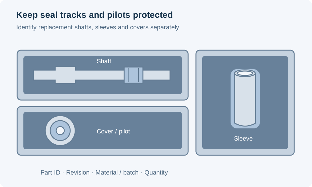
A shaft, a separate sleeve and a cover in individual protective compartments, with covers over a shaft surface and the cover pilot and distinct part identity records

Material and configuration identity

Part references distinguish the specified alloy and equipment configuration. The shaft, sleeve and related cover remain tied to their individual drawing revisions.

Working surfaces separated

Packing prevents hard metal contact across seal tracks, pilots and closure faces. Sleeves and polymer bushings are supported so heavier parts do not bear against their working edges.

Inspection records with the parts

The agreed dimensional and material records accompany the relevant delivery. A replacement part remains traceable to its released definition rather than only to a description such as pump sleeve.

Marine CNC machining FAQs

Can passivation replace a more corrosion-resistant stainless grade?

No. Passivation treats the surface condition; it does not change 316L into a more highly alloyed stainless grade. The original alloy and the joint’s exposure still determine whether it suits the application. Specify the required treatment separately from the material designation and the equipment’s corrosion-selection requirements.

Can salt-spray hours be converted into years at sea?

No direct conversion is justified. ASTM B117 explains that stand-alone salt-spray results do not reliably predict natural exposure performance. If a coating test is required, identify the test method, duration and acceptance criteria; a reported number of hours is not a service-life guarantee.

Should every stainless-to-aluminum joint be electrically isolated?

The isolation detail must agree with the equipment’s electrical bonding and corrosion-protection design. Do not add an insulating sleeve where the assembly intentionally requires a conductive path without an approved change. We machine the released mounting geometry and keep any designated contact areas distinct from isolation seats.

When should a replacement sleeve be finish-machined after installation?

Use the equipment designer’s chosen manufacturing route. An interference fit can change the sleeve’s installed geometry, so some designs reserve a finishing allowance after assembly. The order must then distinguish the supplied blank dimensions from the final installed working diameter and assign the finishing operation explicitly.

Where should drainage details be placed on exposed mounts?

They should remove water from the intended installed orientation without opening a sealed boundary or weakening a required section. A relief in an open bracket is different from a hole through a pump cover. We machine the approved drainage feature; we do not add holes to a closed component as a general marine modification.

Which protective film should be used on spares stored onboard?

The packing specification should name an approved preservative or require a residue-free condition. Fluid-contact areas, polymer guides and elastomer-facing surfaces may restrict what can be applied. State whether the film is removed before installation and who performs that step, rather than assuming one rust preventive suits every part in the kit.

Can water-absorption data set a polymer bushing’s running clearance?

No. A water-absorption percentage describes mass uptake, not the same percentage change in bore diameter. The required clearance depends on the selected grade’s dimensional behavior, the bushing geometry and its installed constraint. Use the equipment’s specified conditioning and installed-bore requirements when ordering the guide.

PROJECT SUPPORT

Discuss your marine equipment component

Share the component drawing, material, quantity and mating-part details. Identify fluid-contact surfaces, exposure conditions and any equipment-specific inspection requirements.

VETCNCCNC MANUFACTURING
English
WhatsApp Email us

Tell us about your project

Share your requirements and we will get back to you by email.

PDF, CAD or ZIP · up to 20 MB