Skip to content
VETCNCCNC MANUFACTURING
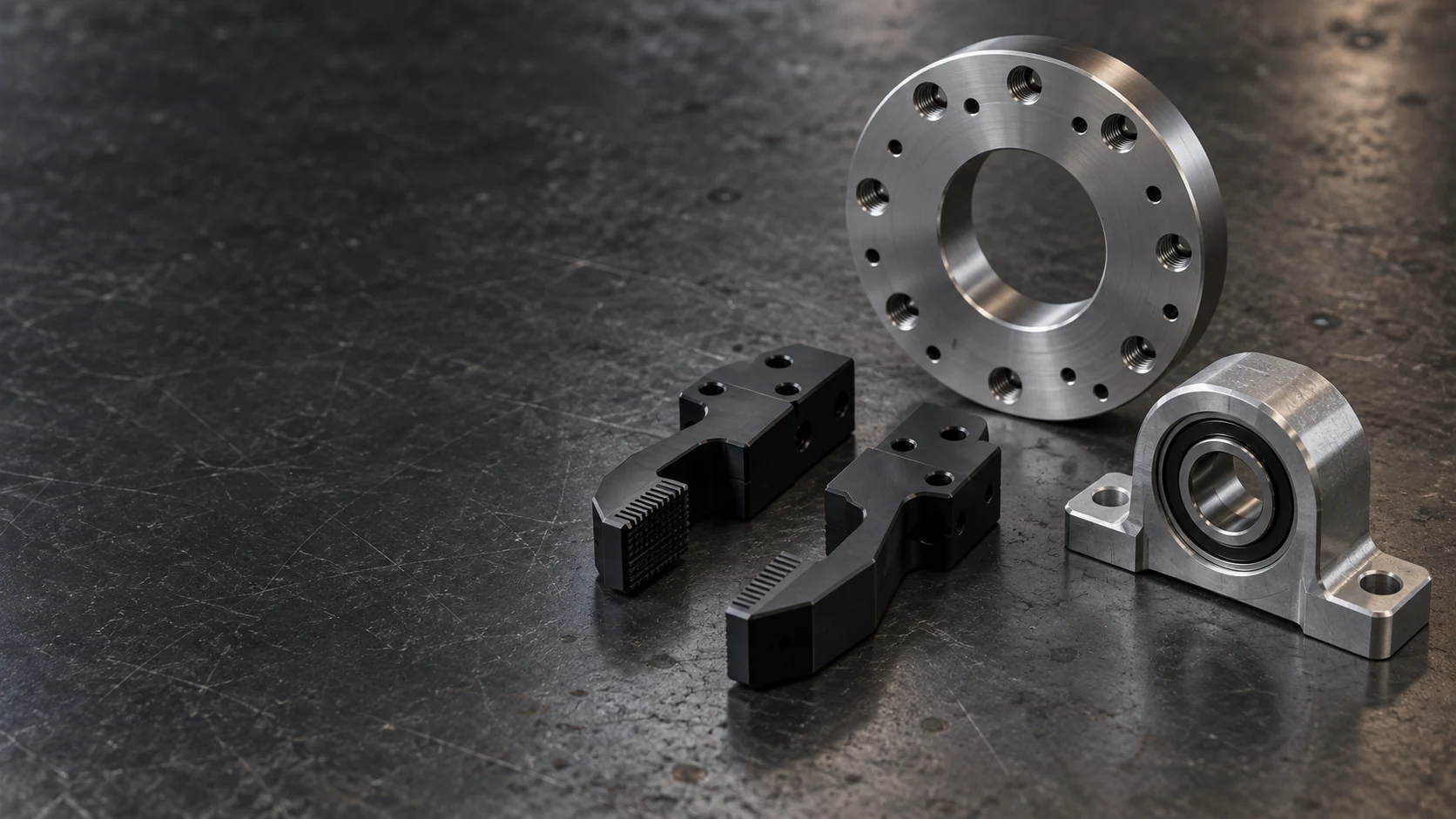
Circular metal interface plate, black gripper fingers and a bearing housing on a dark work surface

Robotics CNC Machining

We machine flange adapters, custom gripper fingers, joint housings and locating fixtures for robot builders and automation integrators. We work from the selected robot, gripper and workpiece interfaces to manufacture the mechanical parts defined by your equipment drawings.

  • Robot-to-tool interfaces
  • Custom gripping parts
  • Mechanism components

Machined robot interfaces, gripping parts and tooling

Our scope is the custom mechanical component between your selected equipment and the task it performs. The six part families cover wrist tooling, mechanism development and workpiece location.

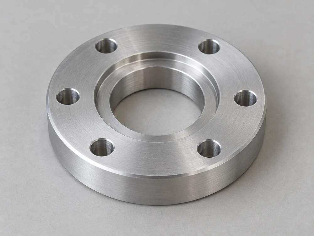
Silver circular adapter plate with six mounting holes, a central through-hole and a concentric locating step

Robot flange adapter plates

Adapters join a robot wrist to a gripper, sensor or tool mounting face. We machine each side’s bolt pattern, locating feature and angular reference, with the plate thickness and offset defined in the assembly design.

  • Wrist patterns
  • Locating features
  • Tool offsets
Discuss this component
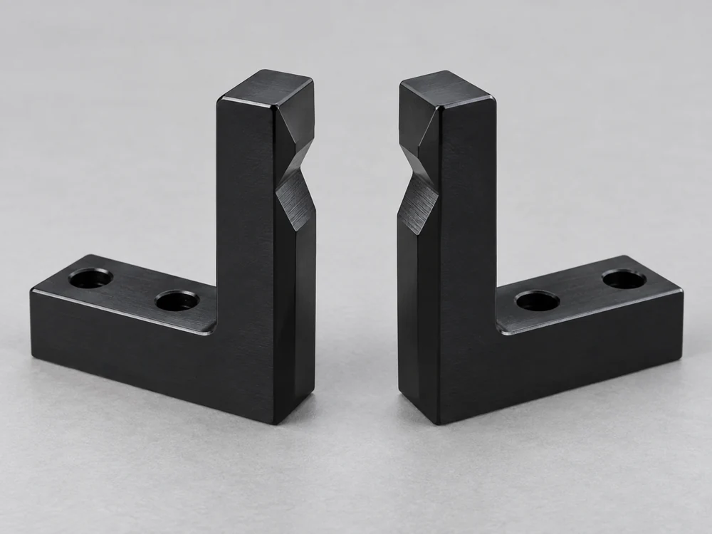
Pair of black L-shaped gripper fingers with mounting holes and opposed V-shaped gripping grooves

Custom gripper fingers

Fingers and replaceable tips connect the selected gripper to the workpiece. We machine the gripper-side mounting features and the specified steps, pockets or contact faces at the gripping end.

  • Finger mounts
  • Contact profiles
  • Replaceable tips
Discuss this component
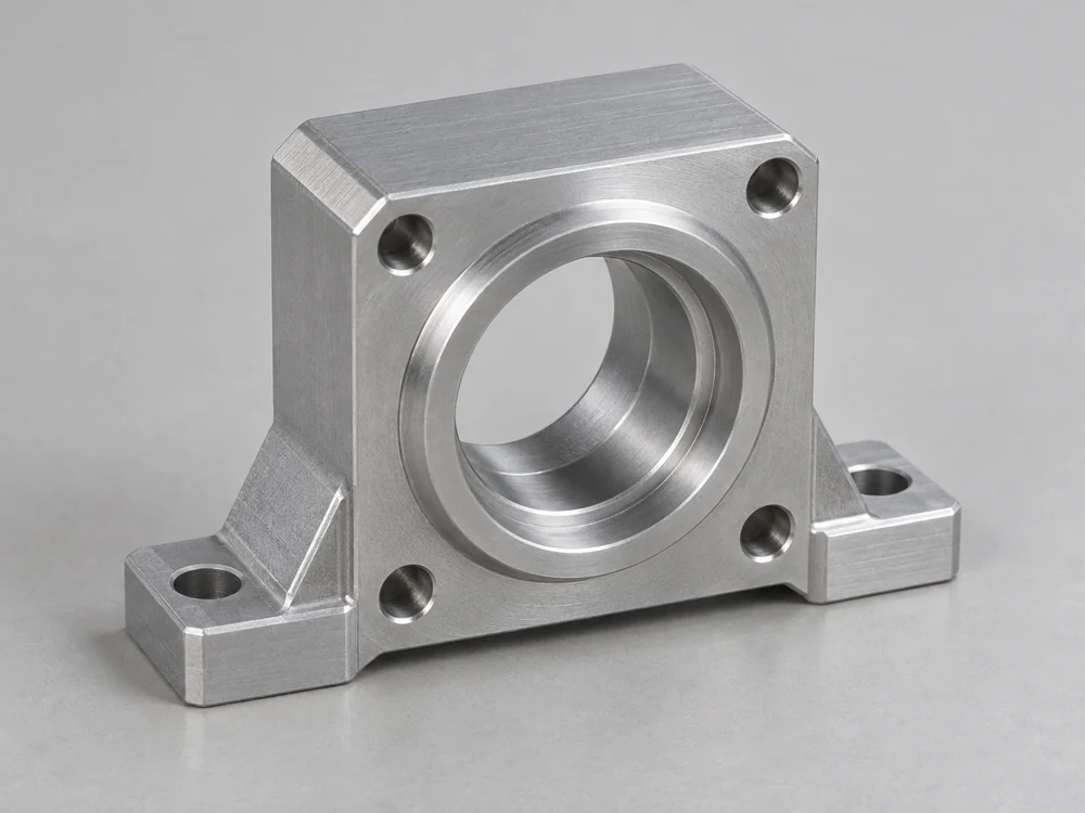
Silver bearing housing with a stepped circular bore, mounting feet and front mounting holes

Joint and bearing housings

Empty housings and support blocks locate bearings, shafts and covers in a robot mechanism. Bearing seats, axial shoulders and connected mounting faces follow the OEM’s component and assembly drawings.

  • Bearing seats
  • Axial shoulders
  • Cover interfaces
Discuss this component
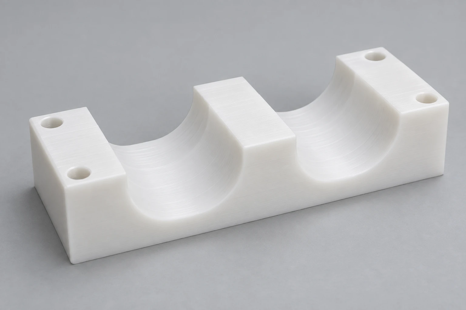
White machined plastic locating nest with two curved support channels and four mounting holes

Workpiece nests and locating fixtures

Nests and locating blocks receive the part during loading, assembly or inspection. Their contacts support the defined workpiece surfaces while leaving room for the gripper to open and withdraw.

  • Support contacts
  • Locating pockets
  • Release clearance
Discuss this component
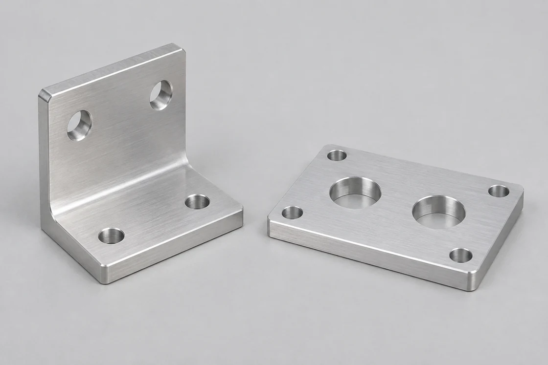
Silver L-shaped mounting bracket beside a flat mounting plate with round holes

Sensor and camera brackets

Brackets place a sensor or vision device relative to the tool or fixture. We machine the mounting face, adjustment features and device pattern without obstructing the required view or connector access.

  • Device patterns
  • Adjustment slots
  • Connector access
Discuss this component
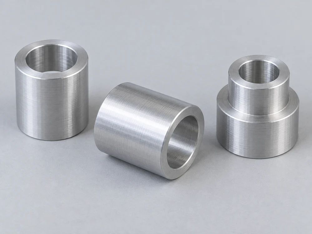
Three silver stand-off spacers with through-bores, including one stepped sleeve

Locating sleeves and spacers

Sleeves, stepped bushings and spacers establish the radial or axial position of adjoining parts. Their working bores, pilots and seating faces are specified together rather than by outside size alone.

  • Working bores
  • Locating pilots
  • Seating lengths
Discuss this component

End-of-arm tooling, part handling and robot mechanisms

An adapter locates a tool on the wrist. A finger contacts the workpiece. A mechanism housing locates the moving components. We keep those manufacturing references explicit instead of treating every robotic part as a mounting plate.

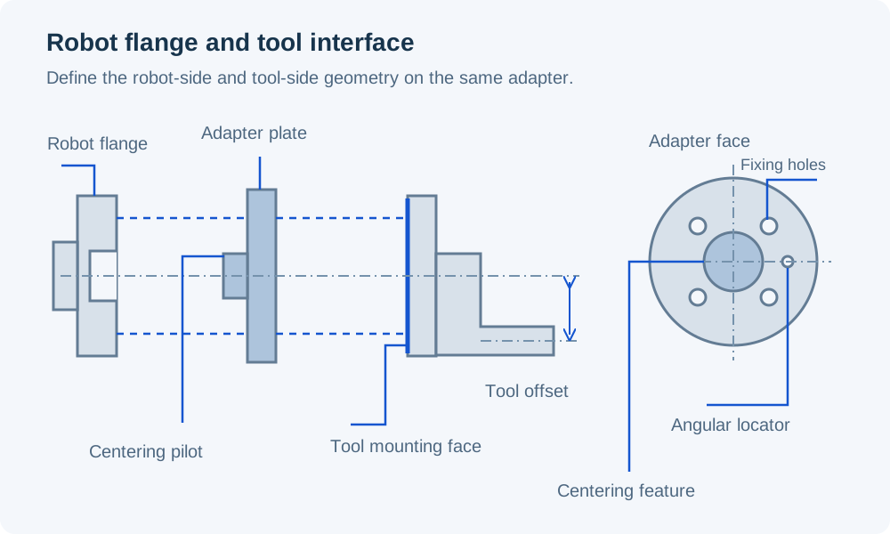
Exploded side view of a robot flange, separate adapter plate and offset tool mount, with an adapter-face detail distinguishing the pilot, fixing holes and angular locator

Joining the wrist flange to the selected tool

We machine an adapter from the robot-side and tool-side interface drawings. Hole count, locating geometry and angular orientation are defined on both sides; a shared flange diameter is not enough to establish the connection.

The model includes the required access for mounting screws and the route for the tool’s cables or hoses.

Location and fastening

Locating features establish position while the fasteners secure the joint. The mating definition determines the appropriate fit and clearance.

Tool installation

The planned tightening sequence must remain accessible once the tool is on the adapter.

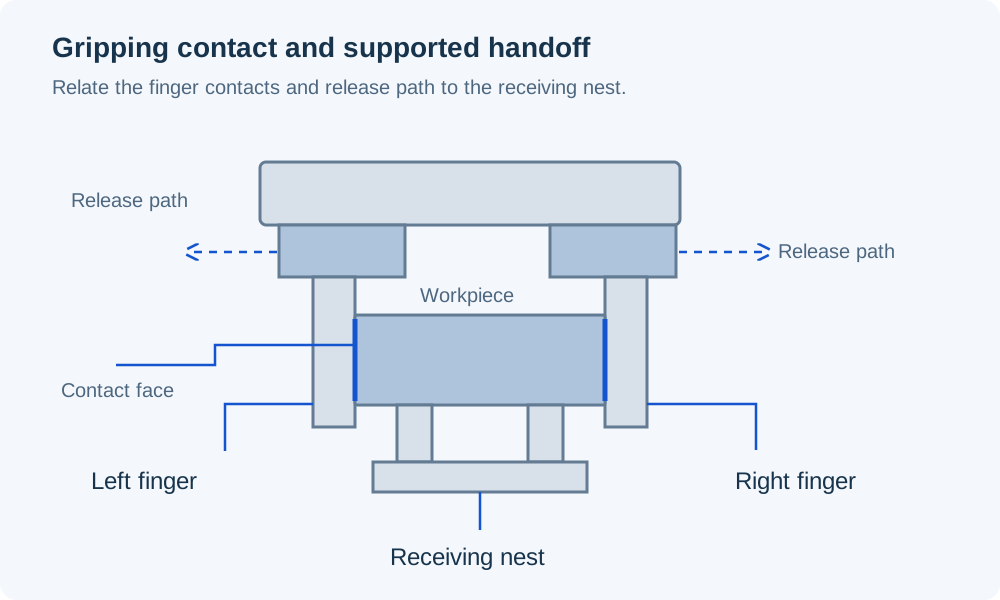
Opposed left and right gripper fingers contacting a workpiece already supported by a receiving nest, with outward release paths clear of the nest

Gripping a workpiece and releasing it into a fixture

We machine the finger contact geometry from the intended gripping surfaces. The shape can provide relief around fragile edges or recesses while retaining the contact regions specified by the gripper designer.

The receiving nest and fingers need compatible access. The nest supports the part at placement; the fingers then open and withdraw without catching a locating wall or dragging across a finished surface.

Defined contact zones

The workpiece drawing identifies where the fingers may touch and which finished, thin or sensitive surfaces remain clear.

Handoff clearance

The fixture layout includes the opening and withdrawal path, not only the workpiece’s final seated outline.

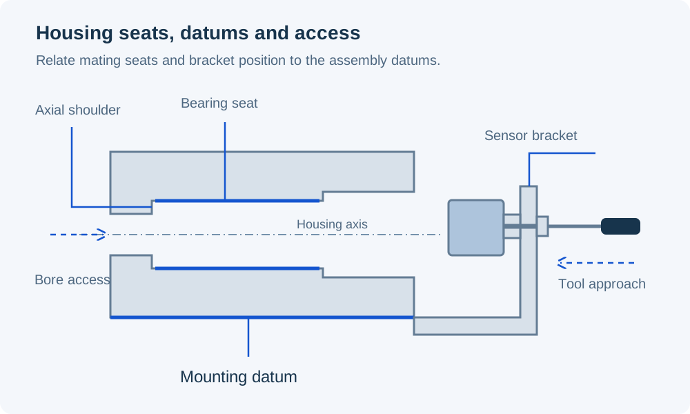
Section of an empty joint housing showing a bearing seat, axial shoulder and mounting datum, with a separate sensor bracket and open bore access

Locating bearings and sensors in a robot mechanism

We machine housings and support details to the chosen bearing and shaft arrangement. Connected bores and axial seats share the drawing’s datum system so that separate setups do not create unrelated locations.

A sensor bracket references the feature it observes. Adjustment slots provide the intended setting range, while the final fastening arrangement holds the selected mechanical position for the OEM’s calibration process.

Bearing arrangement

Bore location, shoulder position and cover clearance follow the selected assembly; the bearing designation alone does not define the housing.

Sensor reference

The mounting datum and field-of-view clearance are defined before an adjustment slot is added.

Interface parts, cell trials and repeat components

We identify what each development delivery is intended to establish, then retain the accepted geometry for repeat machining.

Interface-fit parts

Prototype adapters and fingers check the selected equipment connection, screw access and workpiece clearance before the assembly enters a cell trial.

Trial component set

The intended material and finish are used for the integrator’s gripping, movement and handoff evaluation. Each part revision remains identifiable when observations lead to a design change.

Released parts and replacements

Repeat parts follow the approved interface and contact definition. Replacing a gripper model or changing the workpiece profile is handled as a new configuration wherever the mating geometry changes.

Material parameters for tooling and robot components

Tool mass, part contact and stock strength lead to different material choices. We use the specified grade and condition; these references help distinguish structural aluminum, stainless locating details and polymer contact parts.

Robotics CNC Machining — material parameters
Material / conditionReference parametersComponent context
6061-T6 / T6511 extrusionYield ≥240 MPa; density ≈2.71 g/cm³Adapter plates and tooling bodies
7075-T651 · Kaiser referenceTypical yield 503 MPa; tensile 572 MPaDrawing-specified high-strength fingers or structural details
316L / EN 1.4404Elastic modulus 200 GPa at 20°CSpecified stainless locating and mounting parts
POM-C · TECAFORM AH naturalTensile modulus 2.8 GPa; water uptake 0.05%Replaceable gripping pads and nest contacts

References: Hydro Alloy 6061 extrusion minimum yield and typical density; Kaiser 7075 sheet/coil/plate typical T651 properties; Outokumpu Supra 316L/4404 physical data; Ensinger TECAFORM AH natural (modulus at 1 mm/min; water uptake after 24 h at 23°C). Material values do not define assembled-tool payload or gripping force.

Machining the working faces, seats and profiles

The machining plan follows the component’s working references. An adapter pattern, finger profile and housing bore require different workholding and checks.

Wrist location, finger contact and assembly clearance

We use the features that locate the tool or workpiece as the manufacturing references. A close outside dimension does not compensate for a misplaced contact face or mounting pattern.

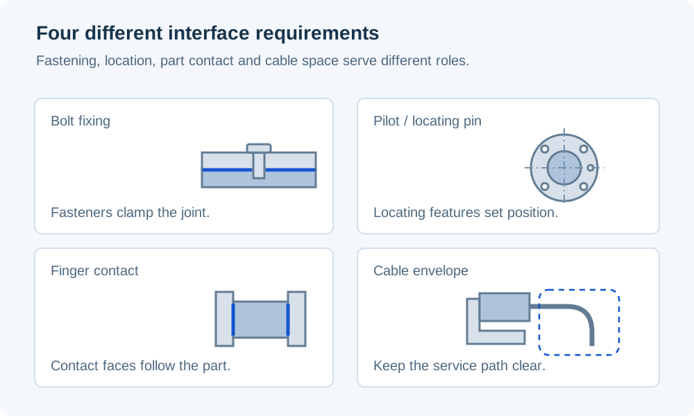
Separate details distinguish joint fixing, pilot and pin location, gripper finger contact faces and the cable clearance envelope

Wrist centering and angular location

A centering feature positions the adapter radially; a separate pin or pattern establishes its orientation. The chosen mating interface determines how those locating features avoid unnecessary constraint.

Finger mount to contact face

The contact profile is dimensioned from the gripper mounting references. Separate left and right geometry is identified where the intended grasp is not symmetrical.

Housing seats and shoulders

The drawing relates bearing seats to their axial stops and adjoining mounting faces. Corner reliefs allow the intended face to seat rather than contact a mating radius first.

Cable and hose access

Openings and reliefs leave the selected connectors reachable. The complete tool layout provides the moving cable or hose envelope; an opening in an isolated plate does not establish clearance through robot movement.

Finishing the mounting and contact surfaces

Fitted interfaces and workpiece contacts need their own final-condition requirements, separate from the general exterior finish.

Gripping contact texture

Finger contact surfaces follow the selected profile, texture and edge treatment. We do not add sharp texture or remove an edge that the gripping design uses to locate the workpiece.

Coated and masked interfaces

For anodized aluminum, the allowance and coverage plan identifies locating bores, pin fits and threads. Those features are checked in the finished condition specified for assembly.

Replaceable contact parts

A separately defined polymer pad or insert can be replaced without remaking the whole finger or nest. Its retaining geometry and thickness remain part of the controlled contact definition.

Selected flange and gripper interface references

The equipment references below show which dimensions define different parts of a robotic attachment. We inspect the custom part against its released drawing, including the mating fit and final surface condition.

Fastener patterns, radial location and angular location are checked as separate features. The gripping profile is measured from the same references used to mount the finger.

Robotics CNC Machining — feature specifications
Mating featureReference dimensionsCustom-part acceptance
UR e-Series tool-flange fastenersBolt circle Ø50 mm; 4 × M6-6HAdapter pattern, orientation and specified hole form
UR e-Series flange centering boreØ31.50 H7Mating pilot fit and face seating per component drawing
UR e-Series flange pin receiverØ6 H7; depth 6.20 ±0.20 mmPin location and engagement per mating definition
Robotiq 2F-85 / 2F-140 side accessory holes2 × M4 × 0.7; centers 12 mm; recommended depth ≤6 mmBracket pattern and screw projection into the gripper
Custom finger contact profileContact dimensions and clearance, mm; drawing limitsProfile relative to finger-mount datums and actual workpiece condition

References: Universal Robots developer drawing for UR3e/UR5e/UR10e/UR16e tool flanges; Robotiq side-accessory mounting guidance, June 2026. Values describe the named mating equipment, not universal robot geometry or adapter machining tolerances. The component drawing defines the mating pilot, pin, hole form and finished condition.

Component inspection and system validation

Our scope is machined components and the inspection specified in the quotation. Robot integration, gripping-force validation, payload assessment, functional safety and system repeatability remain separate responsibilities of the equipment program.

Matched tooling and replacement-part identity

A component record needs to identify the mating equipment and contact geometry, especially when several tools share a similar plate or finger blank.

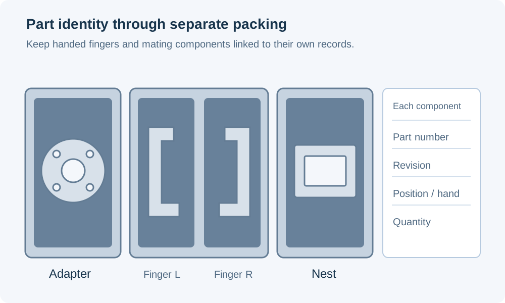
Adapter plate, distinct left and right gripper fingers and receiving nest in separate protective compartments, with part, revision, position and quantity fields

Finger and nest variants

Each distinct gripping profile and receiving nest keeps its own part reference. Left/right markings follow the assembly definition rather than the orientation in which a part is packed.

Interface revision

The adapter and related spacers retain the interface drawing revision used for machining. An amended thickness, locating feature or tool pattern remains visible in the replacement order.

Working surfaces protected

Packing separates gripping profiles, locating pilots and bearing seats from neighboring metal parts. Small replaceable pads and sleeves remain identifiable with their component references.

Robotics CNC machining FAQs

Can one adapter plate fit every robot from the same manufacturer?

No. Interface details can change between robot models. Universal Robots, for example, documents four M6 tool-flange positions on the UR5e and six M8 positions on the UR20. We need the selected model and its tool-interface drawing rather than only the robot brand or payload class.

Is a machined adapter plate an automatic tool changer?

No. An adapter joins the two defined mechanical interfaces. An automatic tool changer also needs a validated locking mechanism and any required utility connections or status functions. We can manufacture a specified plate or component within that design, but a plate order does not include a complete tool-changing system.

Can longer fingers retain the gripper’s original force rating?

Do not assume so. Extending the contact farther from the finger base changes the applied moment. Robotiq’s custom-fingertip guidance requires the design to remain within the gripper’s permitted moment and dimensional limits. The gripper designer must evaluate the new geometry before carrying an existing force or payload rating into it.

Is the nominal workpiece model enough to define a gripping pocket?

It defines the nominal shape, but the pocket also needs a decision about workpiece variation. Cast, molded or unfinished contact surfaces may differ from the final CAD surface. Identify the actual condition being gripped, its dimensional range and the intended relief or contact zones before releasing the finger profile.

Will a polymer contact pad prevent every mark on the workpiece?

No material choice alone establishes that result. Contact pressure, trapped debris, surface texture and the workpiece finish all affect marking. We machine the specified pad geometry and material; the equipment team evaluates it against the actual handled surface and acceptance criteria.

Does changing adapter thickness affect the tool-center-point definition?

Yes, if it changes the tool’s position relative to the wrist. The integrator must account for the resulting offset in the assembled tool definition and review the relevant payload and movement conditions. Matching both bolt patterns does not make an adapter of a different thickness an unchanged tool configuration.

Should replacement fingers be ordered as a matched pair?

Use the assembly’s defined pairing. A single replacement is possible where both fingers have independent, interchangeable definitions. If they were fitted or finished together, the pair needs to be treated as that matched set. Identify the retained finger’s revision and condition rather than assume an unworn new profile will match its worn partner.

PROJECT SUPPORT

Discuss your robot component or tooling

Share the part model, drawing, material and quantity. Include the selected robot or gripper interface and the workpiece contact geometry where they define the component.

VETCNCCNC MANUFACTURING
English
WhatsApp Email us

Tell us about your project

Share your requirements and we will get back to you by email.

PDF, CAD or ZIP · up to 20 MB