Skip to content
VETCNCCNC MANUFACTURING
Bronze-colored flanged sleeve, hexagonal nut and annular thrust washer

CuSn12 Bronze
CNC Machining

Compare Cast-Stock References

Machined CuSn12-C Sleeves, Rings and Guide Components

6 component types

Plain and flanged sleeves

We turn a sleeve’s bore, outside support and end seat as related contacts. A flange supplies an axial stop; the cylindrical section supplies the selected shaft or housing interface. Its final acceptance follows the specified loose or installed condition.

Thrust rings and annular spacers

An annular component establishes an axial contact around the shaft or adjoining hub. We machine its designated end faces and the central opening as one defined component.

Sliding and guide plates

A plate provides a defined sliding face, attachment pattern and edge clearance. We separate the actual contact region from recessed fasteners and exterior reliefs so the mounting hardware does not become an unintended running surface.

Threaded nuts and adjustment details

A spindle nut connects the selected thread to its mounting or retaining geometry. The complete thread form, usable engagement and relationship to the attachment face remain together; an outside hex merely supplies handling access.

Grooved bearing components

A specified groove or feed hole distributes lubricant through its selected path. The component drawing connects the inlet, groove path and intended bearing region, with a defined open route between those features.

Ring blanks and stepped collars

A ring blank or collar can provide an intermediate shape for a later assembly or operation. We machine its identified register, shoulder and retained section; any subsequent tooth cutting, joining or assembly remains an explicit supply stage.

We quote turning, milling, drilling and associated feature finishing in the specified CuSn12-C product. The alloy, casting route and incoming blank remain part of the component definition. The offer covers finished loose components or agreed intermediate machining, with any included finishing and checks identified in the quotation.

CuSn12-C, CC483K and the Selected Cast Product

Continuous-cast stock · GC

Continuous-cast bars and suitable hollow stock provide a regular starting section for sleeves, rings and guide pieces. We retain the ordered casting designation and the section that supplies the finished part rather than treating every nominally similar bronze blank as equivalent.[1]

Selection focus
Regular stock section and retained material

Centrifugally cast blanks · GZ

A supplied centrifugal blank can suit a hollow or ring-shaped component. Its initial bore, outside envelope and end allowance must leave material at the actual finished contacts. The mechanical reference for GZ remains separate from the GC row.[1]

Selection focus
Hollow geometry and the actual stock basis

A supplied shaped casting

A preformed blank can reduce removal around a large shoulder or irregular outline. It also brings casting surfaces and an existing location scheme into the machining route. We distinguish the supplied form from the features we finish and inspect.[2]

Selection focus
Existing form versus included machining

Exact alloy and delivered condition

CuSn12-C / CC483K identifies a tin-bronze casting grade, not a generic brass or an unspecified bearing-metal description. The purchased material definition stays with the drawing and any agreed subsequent thermal or surface processing.

Selection focus
One released material specification
Solid cast-stock geometry with a regular outer section
Hollow cast-stock geometry with material around the bore

Compare like casting routes

The table retains Wisco’s named W-12 / CC483K references for continuous and centrifugal cast products. Tensile and elongation minima differ between the listed routes. Physical values are producer references, separate from the dimensions and acceptance of the machined component.[1]

The selected purchase specification, casting process and actual blank identify the stock used for the order.

Wisco W-12 / CC483K: selected cast-product references
PropertyContinuous GCCentrifugal GZReference basis
Tensile strength Rm≥300 MPa≥280 MPaMinimum; stated cast route
0.2% proof strength≥150 MPa≥150 MPaMinimum; stated cast route
Elongation A,5D≥6%≥5%Minimum; stated cast route
Brinell hardness≥90 HB≥90 HBHB10/1000 reference
Density8.6 kg/dm³8.6 kg/dm³Named W-12 physical reference
Thermal conductivity54 W/(m·K)54 W/(m·K)Named W-12 physical reference
Linear expansion18.5×10⁻⁶/K18.5×10⁻⁶/KNamed W-12 physical reference

Wisco W-12 / EN 1982 CC483K. Its GC mechanical minima apply through 300 mm external stock diameter; larger continuous castings require an agreed material basis. The size condition belongs to the source stock reference, not a VETCNC component-size limit. The purchased material specification governs the order.

Turning and Milling CuSn12-C Working Features

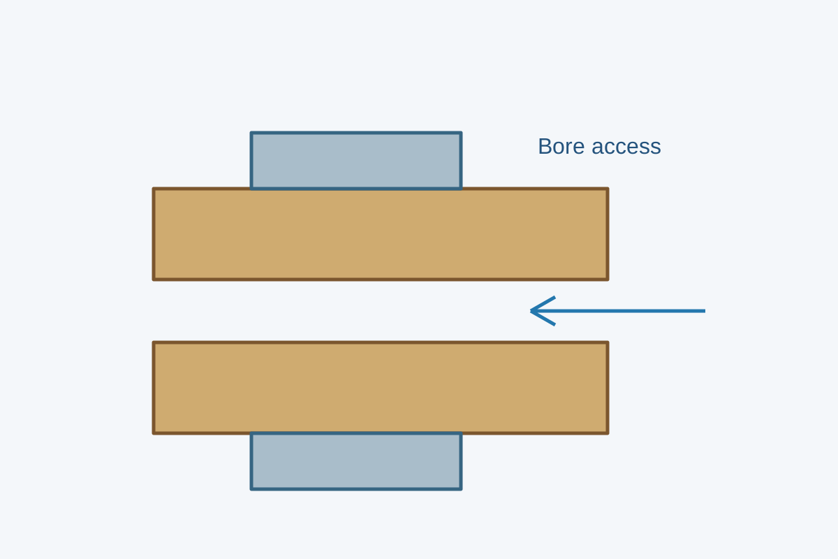
Sleeve section held at a robust outside contact while its bore remains accessible

Bores, seats and end shoulders

Turning establishes the related cylindrical contacts and their axial stops. A hollow blank can reduce bore removal where its available section suits the finished geometry. A second setup carries the selected axis rather than using an unfinished casting skin as the final locating surface.

Guide faces and attachment patterns

Milling establishes the working pad and its related fixing pattern from the selected base reference. Features on the reverse or side face carry that reference through the change of setup instead of taking their positions independently from the raw outline.

Support through the final cuts

A thin sleeve or split section can move under the holding load. We use robust contacts and finish the released part geometry in its required condition; a bore held round under clamping is not automatically round after that restraint is removed.

Bearing Contacts, Axial Seats and Inspection State

Working boreOutside seatAxial contactMating memberRetained wallInspection state
The assembly relationship determines what the dimensions mean
CuSn12-C contacts and accepted machining stage
FeatureWorking requirementAccepted conditionVerification
Sleeve or bearing ringRelated bore, outside support and axial seatSpecified loose or installed stateSize, form and contact relationships
Thrust componentWorking thickness and contact annulusAfter included final operationsFace distances and selected form
Guide plateRunning face and mounting patternDefined support and restraintPosition, surface and motion clearance
Grooved or threaded detailReleased path or complete thread definitionQuoted component or intermediate stageAccessible edges and specified feature limits

Dimensions and final surface requirements follow the released component drawing. Assembly performance and separately required examinations have their own acceptance criteria.

Accept the Intended CuSn12-C Contacts

We measure the specified working bore, faces and attachment details from the component’s functional references after the included final operations.

Details Around a Bronze Contact or Retaining Feature

Leave a defined groove termination

A lubrication groove should end where the released design intends it to end. Its approach to a shoulder, seal or outside edge changes the open path; finishing must not extend that path merely to simplify tool exit.

Keep a useful mounting land

A counterbore or nearby opening removes material beneath a fastener. The remaining bearing area supports the attachment, while its depth leaves the selected hardware clear of the running contact.

Clear the mating transition

A shaft shoulder or inserted member can meet an internal radius before its intended face seats. A defined relief or compatible mating chamfer clears that transition without removing the actual axial support.

Define the retained split or slot

A split, oil slot or local interruption changes the section available for holding and final acceptance. Its edges and endpoint remain tied to the component drawing instead of being treated as an uncontrolled deburring opening.

Discuss Part Requirements

CuSn12-C Components in Bearings, Guides and Mechanisms

Shaft-support components

A sleeve provides the bronze contact within the selected bearing arrangement. The shaft surface, alignment and lubrication remain part of that complete arrangement; the machined sleeve supplies the released geometry within it.

Axial contact details

A thrust ring or washer separates an axial contact from adjacent rotating or stationary pieces. Its working faces and clearance at the bore follow the actual support and retention arrangement.

Machine guides and wear details

A replaceable plate or strip can provide a defined contact in a machine slide or mechanism. Its attachment sits outside the required movement envelope and allows the selected contact piece to be replaced independently of the larger structure.

Adjustment and equipment interfaces

A threaded detail, collar or pump-related ring can connect movement or retention to its receiving body. The component definition identifies the actual connection, included finishing and accepted supply stage.

Finish the Contact Without Losing Its Geometry

A defined lubrication groove stops before the end contact of a sleeve

Retain the working texture

A bore, thrust face or guide pad keeps its specified form and surface texture. Cosmetic polishing on an exterior face need not extend into the working contact or change its accepted size.

Clear the internal intersection

A feed hole entering a bore can leave an edge hidden from the outside. Local finishing removes the projection while preserving the bore surface and the released groove width and endpoint.

Keep processing stages identifiable

An intermediate ring blank and a finished bearing component need different release records. The quotation identifies the included final operation so an earlier machined size is not mistaken for the accepted downstream assembly condition.

Protect the delivered contacts

Packing separates running surfaces and supports thin projections without loading them into a different shape. Part and revision identification remain connected to the specified material and stock route.

CuSn12-C Material and Finished-Feature Inspection

Inspection references distinguish sleeve bore, seating face and working length

Retain the actual cast-product record

The material record identifies the ordered alloy, casting route and supplied stock. A general datasheet is a selection reference; the order’s material evidence identifies the particular product from which the component is made.

Measure from the working references

Bore, thrust face, groove and mounting pattern are checked from their released datums. The selected support or installed condition is retained where it changes the useful acceptance result.

Define additional acceptance separately

Any required assembly, leak, internal-soundness or other functional examination has its own agreed scope and criteria. Each of those examinations is reported against its own agreed scope and criteria.

What Changes the Cost of a CuSn12 Bronze Component?

Solid, hollow or shaped starting blank

A suitable hollow product reduces removal for a sleeve; solid stock can preserve freedom to locate an offset bore. A shaped blank reduces repeated cutting only where it leaves enough material at the finished contacts.

Contact geometry and tool access

Deep seats, slender remaining walls, interrupted bores and local grooves add handling or cutting directions. A part with little finished mass can still require substantial support and material removal.

Final surfaces and included evidence

A specified texture or recorded feature check adds work to its actual contact. Keeping those requirements on the useful regions avoids applying the same finishing operation to unrelated exterior surfaces.

Quantity and shared preparation

Programs, locating preparation and first-part checks are shared across a stable quantity. Individual groove finishing, handling and final checks remain per-part operations; a new stock form or interface can require renewed preparation.

From Cast Stock to Repeat CuSn12-C Components

Release the material and contact geometry

The ordered product connects its exact grade and casting route to the component drawing and the agreed stock allowance.

Establish the first machining route

The first pieces establish locating references, support and access to the specified contact and groove features.

Repeat the accepted definition

The batch follows the released part, material and included final operations. A change of blank or mating interface remains identifiable.

Protect the supplied stage

The packed parts retain accepted contacts and identity, with intermediate blanks kept distinct from components ready for their intended assembly.

CuSn12 Bronze CNC Machining FAQs

Is CuSn12-C automatically a lead-free material?

No. The Wisco CC483K reference permits up to 0.70% lead. Zero lead, or compliance with a particular restricted-substance requirement, therefore has to be specified in its own right alongside the CuSn12-C designation. The end-use material and evidence requirements need to be part of the released purchase specification.

Can an American alloy number be substituted from a cross-reference list?

Not without checking the governing specifications. KMM explicitly warns that its cross-standard equivalence is not absolute and that composition can vary. Its C90800 comparison is therefore a lead for material review, not approval to replace the ordered CC483K product or change its casting route.

Can a hollow-bar bore be used as the finished bearing bore?

Only if it is expressly accepted as that finished surface. For its GC hollow stock up to 97 mm outside diameter, Schreier lists an outside allowance of +0.6 / −0 mm and an inside allowance of −1 / +0 mm. Those are named blank tolerances, not a finished bearing fit. The machining allowance and final bore requirement still need to be connected.

Can a machined CuSn12-C guide be bent to correct its installation?

Do not assume that forming route is suitable. Alumeco rates both cold and hot formability as poor or not recommended for its named CuSn12-C product. An offset that belongs in the component should be released in its geometry or a separately approved manufacturing route rather than created through an uncontrolled installation bend.

Does seawater-resistance wording establish compatibility with an ammonia cleaner?

No. A general corrosion description does not cover every cleaning chemical. Alumeco’s March 2025 CuSn12-C sheet rates water and alkaline exposure as good, but acids and ammonia as poor or not recommended. The actual cleaner, exposure and component use need their own material basis rather than approval from seawater wording.

Are CC483K and CB483K the same supply item?

They refer to different stages in KMM’s material directory: the casting and the ingot used for casting. Its listed chemistry requirements are not identical between those tables. A machining order needs the specified component blank or cast product; an ingot designation alone does not define that finished-stock supply.

PROJECT SUPPORT

Discuss Your CuSn12-C Bronze Component

Send the sleeve, ring, guide or threaded-component drawing with the exact material specification, casting route, quantity and required final condition. Identify the working contacts and included acceptance for the quotation.

CuSn12-C Product and Stock References

Named cast-product values and scope distinctions used for stock selection and machining decisions.

  1. Wisco — W-12 / EN 1982 CC483K CuSn12-CGC and GZ minimum mechanical references, continuous-stock size condition and named physical values.
  2. Schreier Metall — CuSn12-C / CC483KCast-stock product forms and the distinction between blank-size allowance and finished component dimensions.
  3. KMM — CuSn12-C / CuSn12-B, CC483K / CB483KSeparate ingot and casting references; cross-standard comparisons are not absolute equivalence.
  4. Alumeco — EN CuSn12-C / CC483K, 6 March 2025Named product guidance on forming methods; subsequent processing requires its applicable material and supply definition.
VETCNCCNC MANUFACTURING

Get a Quote

Upload Drawing

*Required fields

Acetal part geometry illustration

Enlarged part geometry illustration

AI-generated part illustration.

English
WhatsApp Email us

Tell us about your project

Share your requirements and we will get back to you by email.

PDF, CAD or ZIP · up to 20 MB