Viewing and inspection panels
We machine panel outlines, mounting holes and access cutouts around the required viewing area. The drawing identifies any stock face to retain and the portions that may be machined.
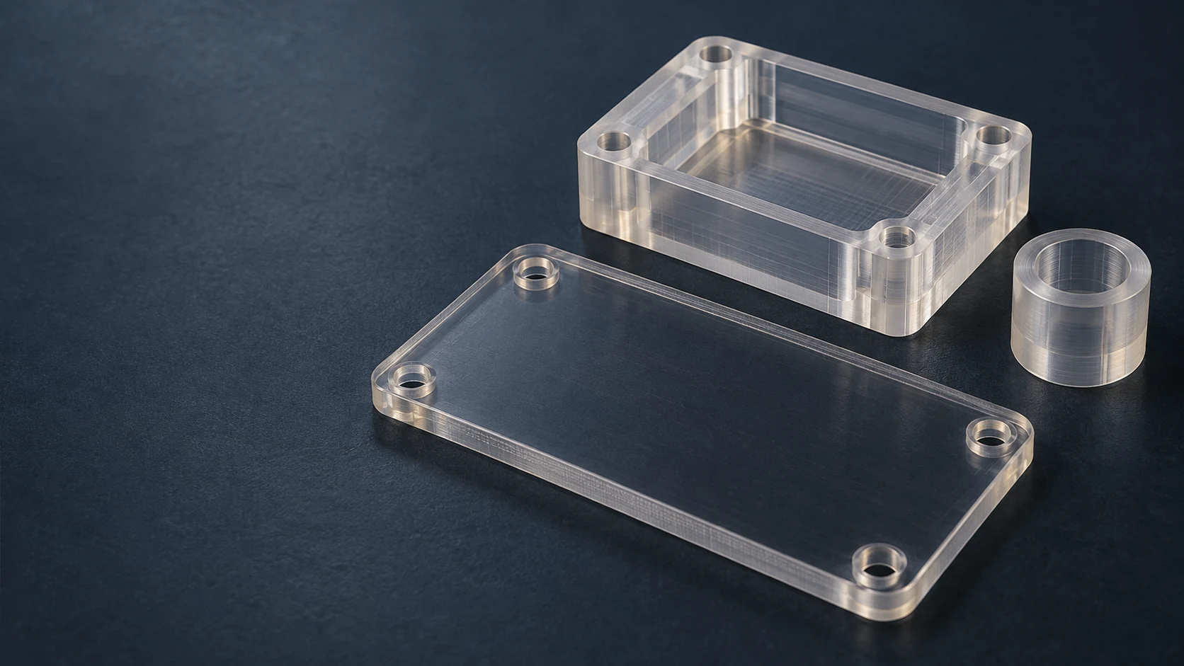
We machine panel outlines, mounting holes and access cutouts around the required viewing area. The drawing identifies any stock face to retain and the portions that may be machined.
Milled PC enclosures combine component pockets with a cover seat and mounting holes. We locate those features from the enclosure datums so the internal assembly and lid share the same reference.
We machine pockets and locating features into clear PC blocks. A visible assembly path can help with positioning, while the defined contacts carry the part and keep delicate features clear.
We mill stepped or L-section supports from solid stock. Mounting-face position, remaining section thickness and access for the fasteners determine how the bracket meets its surrounding hardware.
Turned sleeves separate components through a controlled bore, outside diameter and length. We distinguish locating diameters from clearance surfaces and keep the contact ends square to the specified axis.
We turn annular rings with shoulders or seating steps for drawing-defined assemblies. The retained component establishes the bore clearance, face contact and available wall around the ring.
Clear unfilled stock suits parts where the assembly must remain visible. We identify the viewing zone before choosing which surfaces to machine; transparency of the blank alone does not define the finished view.[1]
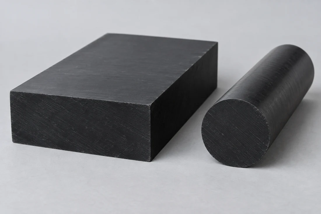
Colored stock suits covers and supports that do not need a clear view. We match the specified color and formulation to the part, with any required performance tied to that grade.[1] [2]
A specified hard-coated sheet can protect the retained sheet faces against scratching. We distinguish the coated faces from surfaces created by machining and keep the coating requirement on the drawing.[3]
Plate suits panels and pocketed bodies; round stock suits sleeves and rings. We choose machining allowances from the finished geometry rather than treating a stock dimension as a finished-part limit.
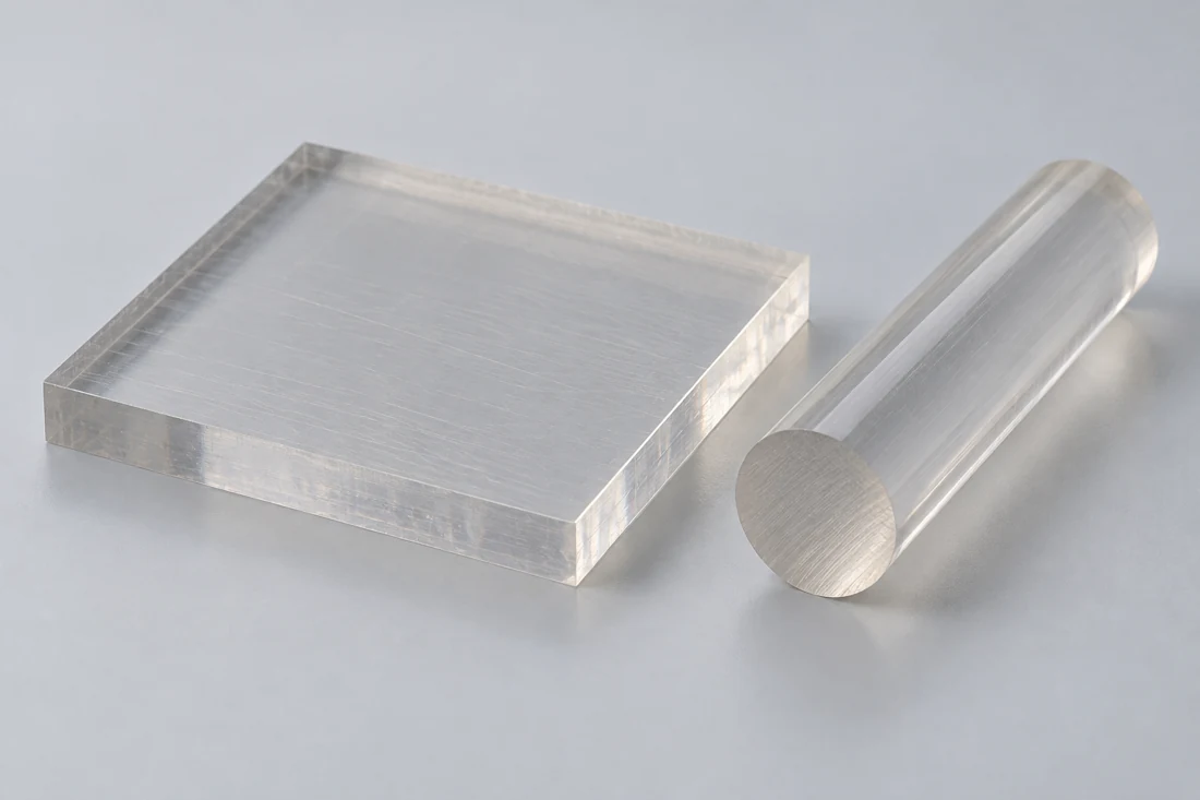
We assess PC when toughness and mechanical attachment matter alongside visibility. A display face with a different appearance requirement may instead suit acrylic. We compare the required viewing area, mounting arrangement and chemical exposure before proposing a material change.[1] [2]
The stock designation and any surface coating remain part of the approved part specification.
| Property | Reference value | Test condition / method | Buyer relevance |
|---|---|---|---|
| Density | 1.19 g/cm³ | Supplier stock data | Component mass |
| Tensile modulus | 2,200 MPa | 1 mm/min · DIN EN ISO 527-2 | Elastic stiffness |
| Tensile strength at yield | 69 MPa | 50 mm/min · DIN EN ISO 527-2 | Short-term tensile response |
| Compression strength | 16 MPa | 1% strain · EN ISO 604 | Contact compression |
| Linear thermal expansion | 80 µm/(m·K) | Longitudinal, 23–60°C · DIN EN ISO 11359-1;2 | Mounting clearance |
Ensinger TECANAT natural, unfilled PC stock shapes; international data sheet. Typical comparison values, not finished-part acceptance limits. Conditions shown apply only to the stated property.
We machine enclosure cavities and support profiles from defined datums. Internal radii, depth and access around a thin wall determine the cutter approach; a hidden sharp corner may need a drawing change before machining.
We turn ring seats, sleeve bores and shoulders around the specified axis. Separating a seating face from a cosmetic surface lets each receive the finish and dimensional control its function needs.
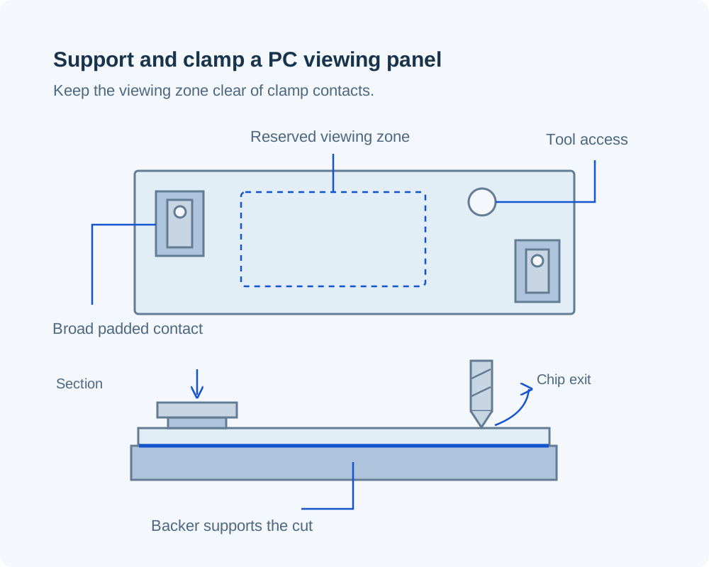
We plan support close to the cut and clamping away from the viewing zone. Sharp tools, chip removal and suitable cooling limit local heat and surface damage during material removal.[2]
| Feature | Reference / requirement | Applicable condition | Verification |
|---|---|---|---|
| Panel length | 0.24 mm expansion per 100 mm | TECANAT natural, free expansion, 23→53°C, longitudinal | Drawing allowance includes restraint and mating material |
| Sheet fastener edge distance | Hole-edge clearance ≥2D and ≥2t | TUFFAK sheet guidance; D = hole diameter, t = thickness; slots need more | Check against approved hole layout |
| Sleeve or retaining seat | Bore, shoulder and seating-face limits | Drawing-specified free or mounted condition | Diameter and axial-location measurement |
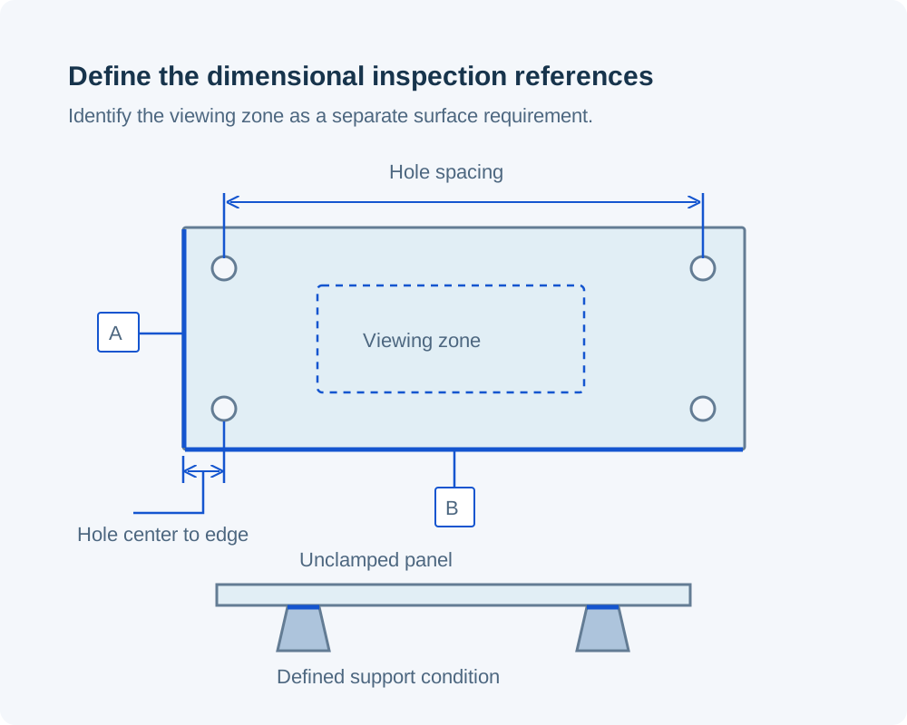
| Viewing zone | Retained face or approved finished surface | Specified viewing direction and lighting | Separate appearance acceptance |
Sheet guidance and calculated movement are design references, not universal machining limits. The component drawing defines final dimensions and acceptance. Sources: Ensinger TECANAT natural; Plaskolite TUFFAK fabrication guidance.
We separate mounting locations, internal component clearance and the viewing surface on the drawing. The tolerance review then addresses the features that control assembly instead of applying one limit to every edge.
For PC sheet, flat bearing faces and washers spread fastening load. We review countersunk seats carefully because a tapered screw head can force the hole outward.
A thin remaining wall can move during cutting or assembly. We review the pocket floor, corner transitions and available support together, keeping the tool and clamp away from unsupported edges.
A cover needs space for connectors, moving components and fastener ends, as well as an outside profile that fits. We machine the lip and mounting datums from the assembly definition, not just the visible outline.[2]
We keep screw heads, ribs and identification outside the area the operator needs to see through. The specified viewing direction also determines whether a machined edge will obstruct the view.
We machine windows and covers that allow an operator to see a mechanism or indicator. The panel outline, viewing direction and access openings define the part; equipment guarding requirements remain a separate design specification.
Clear fixture blocks can keep an alignment feature visible while the part is held. We locate the support pockets and fasteners around that sight line so the fixture serves both positioning and observation.
We machine bodies and covers around the supplied component envelope. Connector cutouts, cover engagement and mounting references establish the mechanical enclosure without assuming electronics or sealing performance.
Sleeves and rings can locate or separate components where PC has been specified. We machine the bearing faces and locating diameters to the assembly drawing, including the clearance around adjacent parts.
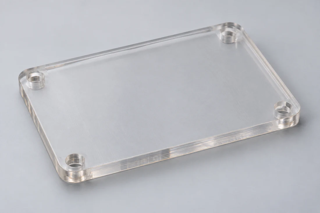
For a flat viewing panel, we can plan the outline and hole operations around an approved stock face. The drawing marks that face so it is not inadvertently included in a thickness-machining operation.
Milled and turned surfaces show a different texture from an untouched clear sheet face. We specify their finish separately and remove loose burrs without changing locating corners or small seating steps.
We agree the viewing direction, lighting and areas inspected before producing appearance-critical parts. A lens prescription or quantified optical test needs its own requirement and manufacturing review.
We separate clear faces from neighboring parts and place identification outside the viewing area. The agreed masking and packaging protect the approved surface until it reaches the assembly stage.
We retain the specified stock identity with the order. For coated sheet, the record also identifies which face carries the coating so receiving inspection can check the correct orientation.
We record the agreed hole positions, pocket sizes or turned seats against the drawing revision. Measurements identify their datums and support condition, allowing the result to be related to the actual assembly.
We keep appearance inspection separate from dimensional results. Any required mounted trial, cleaning exposure or optical measurement has defined acceptance conditions and an assigned test responsibility.
Preserving a sheet face may change the available thickness choice. A fully pocketed enclosure instead needs enough stock for its cavity and outer surfaces; we quote the blank that suits that route.
Deep narrow pockets, hidden shoulders and small internal corners affect access and machining time. We identify a difficult feature directly so a design alternative can be considered without changing the whole part.
A broad cosmetic area needs different handling from a hidden spacer. Including the viewing-zone acceptance and recorded dimensions at quotation keeps surface work and inspection in the same scope.
Parts with a common outline but different cutouts can share useful setup features. We quote the quantities by variant and identify the common datums rather than treating each revision as the same part.
We review the model with the drawing, identifying retained stock faces, machined features and the surrounding hardware. This establishes what must remain visible and what must fit.
We define the recorded dimensions and appearance checks before the first part is made. If the part is assessed in a frame, the agreed mounting arrangement accompanies the sample.
We use the approved grade, face orientation and drawing revision for the batch. Any change to a cutout, coating boundary or mating interface is resolved before further machining.
We separate the parts for shipment and keep identification clear of the viewing zones. Repeat orders retain the approved surface criteria as well as the dimensional revision.
We do not treat a damaged hard-coated face like an ordinary uncoated surface. Plaskolite advises against buffing abrasion-resistant coatings because it can further damage the coating and distort the view. For a replacement part, identify the affected viewing area and retain the specified coating requirement.
We need the exact product and its compatibility approval for the chosen PC grade. Plaskolite advises against threadlockers on TUFFAK sheet because they can cause cracking and crazing; a metal-to-metal assembly practice is not sufficient approval.
No. We agree masking for handling and shipment, but it is not an outdoor protective layer. Plaskolite warns that prolonged sun or heat exposure can make TUFFAK masking difficult to remove; follow the selected stock’s removal instructions.
No. They create different stresses and need different pilot-hole definitions. We use the specified screw and hole design. Plaskolite’s TUFFAK guidance favors thread-cutting over thread-forming screws for lower residual radial and hoop stress, subject to the application.
No. PC can develop environmental stress cracking from combined chemical exposure and stress even when the dry assembly fits. We would need the assembled loading, cleaner, concentration and temperature in the validation plan, rather than relying on an unstressed stock coupon.
We can review the flat blank, but the finished bent shape is a separate part condition. Bending changes the mounting geometry, and the selected coating may limit forming. We need the final shape, bend process and responsibility defined before quoting the machined blank.
No. We need the exact grade and applicable thickness classification. For example, Ensinger’s US TECANAT natural sheet lists HB at 1.47 mm using injection-molded data. That entry does not establish V-0 for a machined enclosure or its assembly.
Share your component drawing, PC stock specification and required quantities. We will review the viewing areas, mounting features and acceptance requirements.
Named stock data and sheet-fabrication guidance used for the references on this page.
